ASTM D689–03 Standard Test Method for Internal Tearing Resistance of Paper
检测样品 造纸
检测项目

 银牌会员
0 篇解决方案
银牌会员
0 篇解决方案
方案详情文
智能文字提取功能测试中
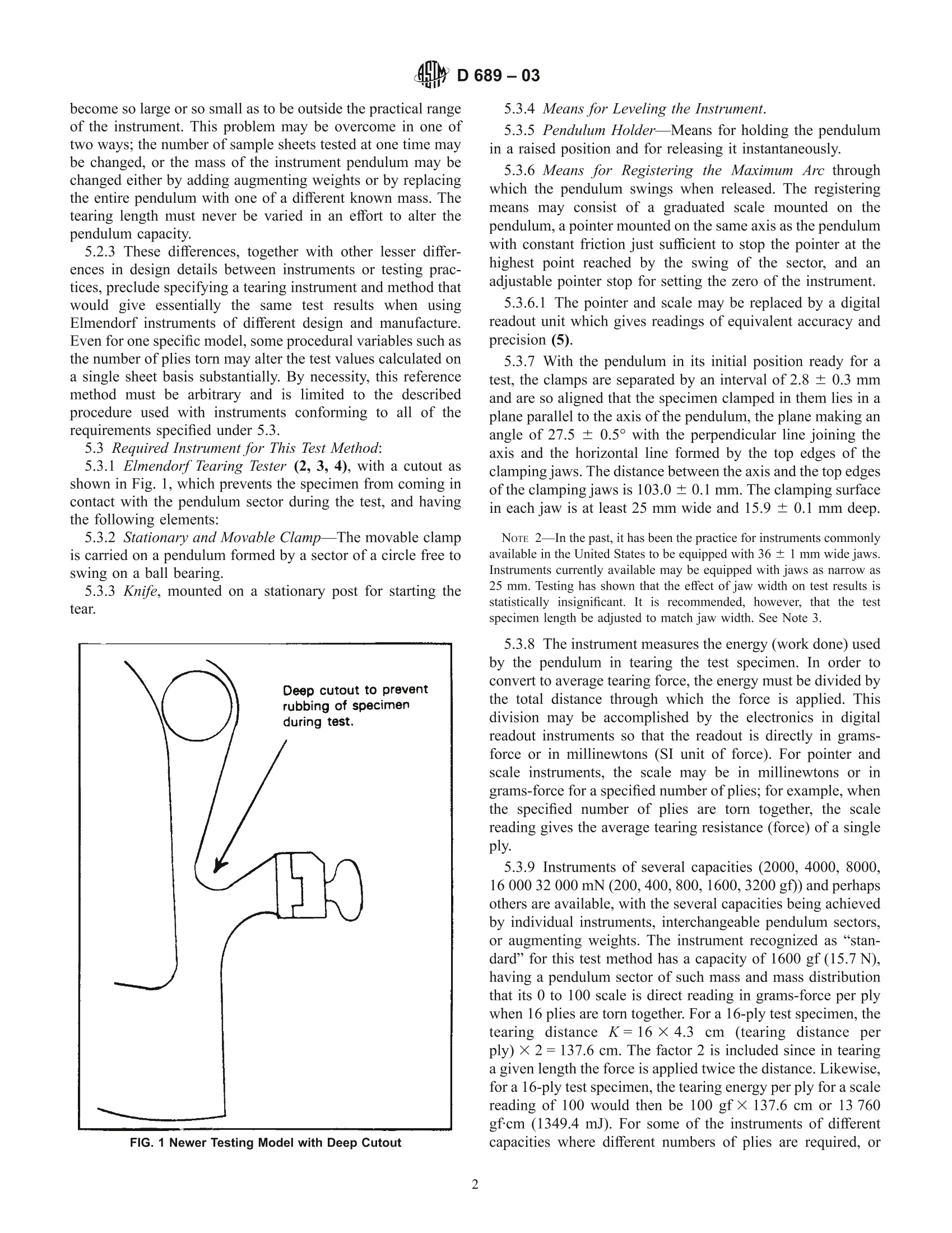
An American National StandardDesignation: D 689 -03 4y D689-g3 Standard Test Method forInternal Tearing Resistance of Paper This standard is issued under the fixed designation D 689; the number immediately following the designation indicates the year oforiginal adoption or, in the case of revision, the year of last revision. A number in parentheses indicates the year of last reapproval. Asuperscript epsilon (E) indicates an editorial change since the last revision or reapproval. This standard has been approved for use by agencies of the Department of Defense. 1. Scope 1.1 This test method measures the force perpendicular to theplane of the paper required to tear multiple sheets of paperthrough a specified distance after the tear has been started,using an Elmendorf-type tearing tester. The measured resultscan be used to calculate the approximate tearing resistance ofa single sheet. In the case of tearing a single sheet of paper, thetearing resistance is measured directly. NoTE 1-Similar procedures for making Elmendorf-type tear measure-ments are found in ISO 1974 and TAPPI T414. 1.2 This test method is not suitable for determining thecross-directional tearing resistance of highly directional boardsand papers. 1.3 This standard does not purport to address all of thesafety concerns, if any, associated with its use. It is theresponsibility of the user of this standard to establish appro-priate safety and health practices and determine the applica-bility ofregulatory limitations prior to use. 2. Referenced Documents 2.1ASTM Standards: D 585 Practice for Sampling and Accepting a Single Lot ofPaper, Paperboard, Fiberboard, or Related Products D 646 Test Method for Grammage of Paper and Paperboard(Mass per Unit Area) D 685 Practice for Conditioning Paper and Paper Productsfor Testing D 1749 Practice for Interlaboratory Evaluation of TestMethods Used with Paper and Paper Products’ E 178 Practice for Dealing with Outlying Observations’2.21ISO Standard: ISO 1974 Paper—Determination of tearing resistance(Elmendorf method)+ ( T h is test method is under the jurisdiction of ASTM Committee D06 o n P aper a nd Paper P r oducts a n d is t h e direct responsibility of Subcommittee D 0 6.92 on Te s t Methods. ) ( Current e dition approved April 10, 2003. P u b lished Ju n e 20 0 3 . Ori g inally a pproved i n 1 942 a s D 689-42 T. L a st p r evious edition apporved i n 1 996 asD 6 89-96a. Discontinued 19 8 4 an d re i nstated 1 9 92. ) ‘Annual Book of ASTM Standards, Vol 15.09. Annual Book of ASTM Standards, Vol 14.02. Available from American National Standards Institute, 25 W. 43rd St.,4thFloor, New York, NY 10036. 2.3 TAPPI Standard: TAPPIT414 InternalTTearingResistance of Paper(Elmendorf-Type Method) 3. Summary of Test Method 3.1 One or more sheets of the sample material are torntogether through a fixed distance by means of the pendulum ofan Elmendorf-type tearing tester. The work done in tearing ismeasured by the loss in potential energy of the pendulum. Theinstrument scale is calibrated to indicate the average forceexerted when a certain number of plies are torn together (workdone divided by the total distance torn). 4. Significance and Use 4.1 This test method is widely used within the paperindustry, in conjunction with other tests of strength, as apredictor of end-use performance of a wide range of grades ofpapers. 5. Apparatus 5.1 Elnnendorf-Type Tearing Tester—Severa ypesavailable and in use throughout the world, principally those ofAustralian, British, German,Swedish, and United States manu-facture. In addition, testing practices also vary. 5.2 Instrumental and Procedural Variables-Instrumentsand practices in use vary in at least two major respects: 5.2.1 The Design Of The Specimen Clamps-Together withthe structural characteristics of the paper governing the natureof the tear with respect to its splitting tendencies during thetest, this has an appreciable influence on the mode of tearingand may result in significant differences (1). The proceduredescribed in 5.3.7 reduces this effect. The clamp designs usedby some manufacturers may vary even for their own models.Instruments are available with pneumatically activated grips aswell, which minimizes variations due to differences in clamp-ing pressures exerted by manually tightened grips. 5.2.2 A Combined Variation inTesters and TestingPractices-As measured tearing resistance increases or de-creases for different types of paper, the measurement may ( ’ Available f r om the Technical Association of t he Pul p and Paper Industrial, P.O. Box 1 05113, Atlanta, GA 30348. ) ( T he boldface numbers in pa r entheses refer to the l i st of ref e rences at the end of this standard. ) become so large or so small as to be outside the practical rangeof the instrument. This problem may be overcome in one oftwo ways; the number of sample sheets tested at one time maybe changed, or the mass of the instrument pendulum may bechanged either by adding augmenting weights or by replacingthe entire pendulum nwi9th one of a different known mass. Thetearing length must never be varied in an effort to alter thependulum capacity. 5.2.3 These differences, together with other lesser differ-ences in design details between instruments or testing prac-tices, preclude specifying a tearing instrument and method thatwould give essentially the same test results when usingElmendorf instruments of different design and manufacture.Even for one specific model, some procedural variables such asthe number of plies torn may alter the test values calculated ona single sheet basis substantially. By necessity, this referencemethod must be arbitrary and is limited to the describedprocedure used with instruments conforming to all of therequirements specified under 5.3. 5.3 Required Instrument for This Test Method: 5.3.1 Elmendorf Tearing Tester (2, 3, 4), with a cutout asshown in Fig. 1, which prevents the specimen from coming incontact with the pendulum sector during the test, and havingthe following elements: 5.3.2 Stationary and Movable Clamp-The movable clampis carried on a pendulum formed by a sector of a circle free toswing on a ball bearing. 5.3.3 Knife, mounted on a stationary post for starting thetear. FIG. 1 Newer Testing Model with Deep Cutout 5.3.4 Means for Leveling the Instrument. 5.3.5 Pendulum Holder—Means for holding the pendulumin a raised position and for releasing it instantaneously. 5.3.6 Means for Registering the Maximum Arc throughwhich the pendulum swings when released. The registeringmeans may consist of fa giraduated scale mounted on thependulum, a pointer mounted on the same axis as the pendulumwith constant friction just sufficient to stop the pointer at thehighest point reached by the swing of the sector, and anadjustable pointer stop for setting the zero of the instrument. 5.3.6.1 The pointer and scale may be replaced by a digitalreadout unit which gives readings of equivalent accuracy andprecision (5). 5.3.7 With the pendulum in its initial position ready for atest, the clamps are separated by an interval of 2.8 ±0.3 mmand are so aligned that the specimen clamped in them lies in aplane parallel to the axis of the pendulum, the plane making anangle of 27.5 ± 0.5°with the perpendicular line joining theaxis and the horizontal line formed by the top edges of theclamping jaws. The distance between the axis and the top edgesof the clamping jaws is 103.0 ± 0.1 mm. The clamping surfacein each jaw is at least 25 mm wide and 15.9 ±0.1 mm deep. NoTE 2—In the past, it has been the practice for instruments commonlyavailable in the United States to be equipped with 36 ± 1 mm wide jaws.Instruments currently available may be equipped with jaws as narrow as25 mm. Testing has shown that the effect of jaw width on test results isstatistically insignificant. It is recommended, however, that the testspecimen length be adjusted to match jaw width. See Note 3. 5.3.8 The instrument measures the energy (work done) usedby the pendulum in tearing the test specimen. In order toconvert to average tearing force, the energy must be divided bythe total distance through which the force is applied. Thisdivision may be accomplished by the electronics in digitalreadout instruments so that the readout is directly in grams-force or in millinewtons (SI unit of force). For pointer andscale instruments, the scale may be in millinewtons or ingrams-force for a specified number of plies; for example, whenthe specified number of plies are torn together, the scalereading gives the average tearing resistance (force) of a singleply. 5.3.9 Instruments of several capacities (2000,4000,8000,16 000 32 000 mN (200,400,800,1600,3200 gf)) and perhapsothers are available,with the several capacities being achievedby individual instruments, interchangeable pendulum sectors,or augmenting weights. The instrument recognized as “stan-dard”for this test method has a capacity of 1600 gf (15.7 N),having a pendulum sector of such mass and mass distributionthat its 0 to 100 scale is direct reading in grams-force per plywhen 16 plies are torn together. For a 16-ply test specimen, thetearing distance K=16×4.3 cm (tearing distance perply)×2=137.6 cm. The factor 2 is included since in tearinga given length the force is applied twice the distance. Likewise,for a 16-ply test specimen, the tearing energy per ply for a scalereading of 100 would then be 100 gf× 137.6 cm or 13 760gfcm (1349.4 mJ). For some of the instruments of differentcapacities where different numbers of plies are required, or when the number of plies tested using the “standard”instru-ment differs from 16, different values of K or the tearing energyper ply, or both, may be calculated. 5.3.10 In the“standard”instrument, the zero reading on thescale is at about 70° from the center line (that is, the verticalbalance line when the pendulum hangs freely), the 100 readingis at about 21° from the center line, and a vertical force of1057.3±2.0 gf (10.369±0.020N) applied at 22.000 ±0.005cm from the pendulum axis is required to hold the pendulumsector at 90°from its freely hanging position. Other tearinginstruments will require vertical forces that are factors of 2greater or smaller than 1057.3 gf and, if calibrated in millin-ewtons, the zero reading would remain at 70° and the 1000reading would be at about 19°(or the 981 reading at about21°). 5.3.11 The cutting knife for the test specimen is centeredbetween the clamps and adjusted in height so that the tearingdistance is 43.0± 0.2 mm; for example, the distance betweenthe end of the slit made by the knife and the upper edge of thespecimen is 43.0 ± 0.2 mm when the lower edge of the63.0-mm wide specimen rests against the bottom of the clamp. 5.4 Instruments are available for automated testing thatincorporates automatic sample insertion, automatic samplecutting, etc. in addition to electronic data readout as specifiedin 5.3.4. These automated instruments may be used, providingthe conditions specified in 5.3 are met. 5.5 Specimen Cutter, to ensure parallel specimens 63.0 ±0.15 mm wide with sharp and clean edges. For this purpose, itis desirable to use the type having two hardened and groundbase shears, twin knives tensioned against the base shears, anda hold-down mechanism. 6. Sampling and Test Specimens 6.1 Obtain the sample to be tested in accordance withMethods D 585. 6.2 From each test unit of the sample, prepare ten represen-tative specimens in each principal direction of the paper, unlessa test in only one direction is required. For each specimen,arbitrarily designate one side of the material in some way, suchas “primary side”, “print side",“wire side",“side one”, etc. Foreach specimen, keep the designated sides of all the plies facingthe same way. NoTE 3-It has been found (6) that there is usually no advantage intesting more than ten specimens of a homogeneous test unit of the sample. 6.3 Cut each ply for a test specimen so that its dimension onthe side placed in the clamps is at least 53 mm and thedimension through which the tear will be propagated is 63.0 ±0.15 mm. Take all the plies to be torn together from a singlesheet. If sufficient material is not provided, take from adjacentsheets of a unit. NoTE 4—The correct dimension for the side of the test specimen thatwill be placed in the clamps is equal to the distance between the outermostedges of each of the instrument’s jaws (±2 mm). For the instrumentdescribed in 5.3, that distance is at least 2 × 25 mm (the minimum widthfor each jaw face) plus 2.8 mm (the distance between the clamps) or atleast 53 mm. In the United States, the majority of the instruments havejaws 36+1 mm wide. A dimension of 76 ± 2.0 mm for the side of thesample to be held in the clamps is correct. 7. Calibration and Adjustment 7.1 As noted in Section 5, several Elmendorf-type testersare available and in use at the present time. Minor differencesin calibration or adjustment procedures, or both, may apply toinstruments obtained from different vendors that comply with5.3, thus specific calibration procedures which may be used forall instruments complying with 5.3 is impossible. The infor-mation contained in this section is to be used as a guide inplacing an individual instrument into proper calibration for usein performing the test. 7.2 Verification of Scale-Once the scale has been verified,it is unnecessary to repeat this step, provided the tester is keptin adjustment and no parts become changed or perceptiblyworn. The scale may be verified either by the potential energymethod or by the method which uses the check weightsobtainable from the manufacturer. The potential energy methodis relatively time-consuming and complicated. The checkweight method is relatively simple. 7.2.1 Potential Energy Method-The procedure (7) forverification is as follows: Anchor and level the tester. Clamp aknown weight (in grams), W, to the radial edge of the sectorbeneath the jaws, the center of gravity of the weight (includingmeans of attaching) having been previously marked by apunched dot on the face of the weight that is to be toward thefront of the instrument. Close the jaw of the clamp in the sector.Raise and set the sector as for tearing a sheet and, by means ofa surface gage or cathetometer, measure in centimetres, to thenearest 0.01 cm, the height, H, of the center of gravity of theweight above a fixed horizontal surface. Then release thesector, allow it to swing and note the pointer reading. Withouttouching the pointer, raise the sector until the edge of thepointer just meets with its stop, in which position againdetermines the height, h, of the center of gravity of the weightabove the fixed surface. 7.2.2 Use the following formula for the standard 1600-gftester: where: the pointer reading = W(h-H)/K, and K =137.6 cm. For other instruments graduated for grams-force of greater orlesser capacity, the reading will be factors of 2 greater orsmaller. If graduated for millinewtons, the additional factor9.81 must be applied. 7.2.2.1 One or more weights may be clamped on the edge ofthe sector for each calibration point. The work done in raisingeach weight is calculated and added together. 7.2.2.2 If the deviations of the indicated readings are greaterthan one-half division, the instrument should be returned to themanufacturer for repair and adjustment. 7.2.3 Verification of Scale-Check Weight Method-Usecheck weights calibrated for suitable scale values (that is, 20,50, and 80 %of pendulum capacity.) Different check weightsare needed for each pendulum capacity. These weights shouldbe so constructed that each weight can be inserted in theclamps by the procedure used for a test specimen. 7.2.3.1 With the pendulum in the raised position, open theclamp of the pendulum. Slide the weight into position andfasten it securely into the clamp. The body of the weight mustbe beneath the clamp. Depress the pendulum stop, thusreleasing the pendulum. Hold down the stop until after thependulum swing is completed, and catch the pendulum on thereturn swing. Read the indicating device to the nearest division. 7.2.3.2 Repeat this procedure with each of the checkweights 7.2.4 Verification of Scale-Purchased Calibration WeightMethod-Calibration weights may or may not be availablefrom the manufacturer of the instrument for use in calibration.Order calibration weights at the same time as the instrument(see 7.2.4). 7.3 Adjustment of Tearing Distance—To check the 43.0-mmtearing distance, apply a small amount of graphite (from anordinary pencil) to the cutting knife. When the cut is madesome of the graphite transfers to the paper, contrasting the cutfrom the uncut portion of the paper and facilitating themeasurement. Make this measurement with a vernier caliperwith a depth gage or a quality steel rule, readable to 0.2 mm orbetter under magnification. An alternative procedure is to use ago, no-go gage, which may be available from the manufacturerof the instrument. 7.4 Adjustment of Instrument for Operation: 7.4.1 Pendulum Notching-Sometimes, as a result of fre-quent use, a notch is worn in the pendulum sector at the pointof contact with the sector stop, giving a jerky release of thependulum. If this happens, either repair the sector by cuttingout and replacing the worn edge, or adjust the height of the stopto the very lowest point of the sector edge. In this case, recheckthe calibration of the scale. 7.4.2 Clamp Alignment and Knife Condition-Rest thependulum sector against its stop, and check the alignment ofthe clamps. Adjust the pendulum stop if necessary. Verify byvisual check that the knife is centered between the clamps, andadjust if necessary. Check the sharpness of the knife. A dullknife will result in a square notch near the top of the cut withthe paper pushed out. If necessary, sharpen the knife with arough stone; a rough edge is better than a sharp, smooth edge.Check the tearing distance and adjust the height of the knife ifnecessary. Do not change the dimensions of the specimen toadjust the tearing distance. 7.4.3 Instrument Mounting—Support the instrument on atable so rigid that there will be no perceptible movement of thetable or instrument during the swing of the pendulum. Anymovement of the instrument base during the swinging of thependulum may be a significant source of error. NoTE 5—Threaded bolt holes are usually provided in the base of theinstrument and may be used to secure the instrument to the table. Analternative procedure is to place the instrument on a guide which ensuresthat the instrument always has the same position on the table. Such a guides mmay be available from the manufacturer of the instrument. 7.4.4 Instrument Leveling-Level the instrument so thatwith the sector free, the line on the sector indicating the verticalfrom the point of suspension is bisected by the edge of thependulum stop mechanism. 7.4.5 Pendulum Friction (Older Instruments)-Draw a pen-cil line on the stop-mechanism 25 mm to the right of the edgeof the sector stop. Raise the sector to its initial position and setthe pointer against its stop. On releasing the sector and holdingthe sector stop down, the sector should make at least 20complete oscillations before the edge of the section whichengages the stop no longer passes to the left of the pencil line.Otherwise, clean, oil, and adjust the bearing. 7.4.6 Pendulum Friction (Newer Instruments)—In recentyears, a new typeof frictionless bearing made of syntheticmaterial has been used. This bearing will not necessarily allowthe pendulum sector to make 20 complete oscillations as theolder one did. This does not mean that there is excess frictionin the pendulum swing. These newer bearings should not beoiled. Consult the instructions supplied with the instrument forguidance. 7.4.7 Pointer Zero Reading-Operate the leveled instru-ment several times with nothing in the jaws, the movable jawbeing closed. If zero is not registered, the pointer stop shouldbe adjusted until the zero reading is obtained. Do not changethe level to adjust the zero. 7.4.8 Pointer Friction-Set the pointer at the zero readingon the scale before releasing the sector, and after release seethat the pointer is pushed not less than 2.5 mm nor more than4.0 mm beyond the zero. If the pointer friction does not causeit to lie between these two distances, remove the pointer, wipethe bearing clean, and apply a trace of good clock oil to thegroove of the bearing, adjust the spring tension or make otheradjustments to achieve the specified friction. Reassemble,readjust the zero setting, and recheck the pointer friction. 7.5 Instruments with Digital Readout-For instrumentswith digital readout, the pointer is generally absent. Thesespecifications relating to the pointer are ignored and the valuesfrom the digital readout employed are used for zeroing andscale verification. 8. Conditioning 8.1 Precondition the sample on the dry side and condition inaccordance with Practice D 685. 9. Procedure 9.1 Level and adjust the testing apparatus, if necessary,before each set of tests. 9.2 Make all tests under standard atmospheric conditions inaccordance with Practice D 685. 9.3 Raise the pendulum sector to its initial position and setthe pointer against its stop. 9.3.1 When a digital readout unit is present, ignore instruc-tions in this section regarding the pointer. Operate the readoutunit following the manufacturer’s instructions. 9.4 Center the specimen in the clamps with the bottom edgecarefully set against the stops. Securely clamp the specimen,using approximately the same pressure on both clamps, andmake the initial slit. Depress the pendulum stop as far as it willgo, thus releasing the pendulum. Hold down the stop until afterthe tear is completed and catch the pendulum on the returnswing without disturbing the position of the pointer. 9.5 Determine from a preliminary test or the product speci-fication how many plies are needed to make up a specimen. When torn together on the instrument having a 15.7-N (1600-gf) capacity the plies should give an instrument scale readingnearest 40 % of full scale. NoTE 6-The work done in tearing a number of sheets of paperincludes a certain amount of work to bend the paper continuously as it istorn, to provide for the rubbing of the torn edges of the specimen together,and to lift the paper. The number of plies torn at one time and their sizecan affect the test result with some papers. Empirical requirements forboth the apparatus and the test method are therefore necessary to keep theadditional work not used for tearing to a definite quantity. For this reason,in making comparisons between two or more sets of paper of the sametype and grammage, use the same number of plies for each set. 9.6 If a single-ply test specimen gives a reading higher than75 on the standard 1600-gf instrument (75% of full scale onother instruments), use the next higher capacity instrumentswith one ply or, if necessary, a still higher capacity instrument. 9.6.1 For weaker papers, the standard 1600-gf instrumentmay require that 16 or more plies be torn together under theprocedure specified in 6.3. For these papers, and providedlower capacity instruments are available, the number of pliesmay be restricted to four and the next lower capacity instru-ment may be used whenever the reading falls below 20 % offull scale. ISO 1974 provides for testing four-ply specimenswith multiple pendulum instruments. If this alternative proce-dure is used, state in the report. 9.7 Make only one test per specimen, each specimen con-sisting of the specified number of plies. For each specimenkeep the wire sides of all plies facing the same way. Make testsalternately with the wire sides of all plies toward the pendulumand with the wire sides of all plies away from the pendulum.Make certain that the specimen leans toward and not awayfrom the pendulum by gently creasing the specimen at theclamp if necessary, but in doing so avoid affecting the relativehumidity of the test area. 9.8 Record the number of plies and the scale reading to thenearest half division. 9.9 Note and report if the line of tear fails to pass throughthe top edge of the specimen but deviates to one side. Do notuse the reading obtained. If more than one third of the testsexhibit this behavior, this test method should not be used forthe material concerned. 10. Calculation 10.1 Compute the average of the ten scale readings. Deter-mine by Practice E 178 or by other suitable statistical test,whether a value that appears to be excessively high or lowshould be included in the average. 10.2 Calculate the average tearing force in millinewtonsand, if desired, in grams-force required to tear a single ply asfollows: 10.2.1 If the standard 1600-gf instrument with 0 to 100 scaleis used: Average tearing force, mN 10.2.2 If an instrument of different grams-force capacitywith 0 to 100 scale is used: Average tearing force,mN=(16×9.81 × average scale reading×gf-capacity)/(number of plies × 1600 gf) (4) 10.2.3 If an instrument has an SI metric scale (for example,0 to 1000 graduations): 10.2.4 If an instrument has a direct-reading scale (that is,digital read-out) that directly gives the force per ply whenpreset for the number of plies: Average tearing force, mN= average scale reading if directly in millinewtons,or =9.81 × average scale reading if in grams-force (8) Average tearing force, gf = average scale reading/9.81, if scale is in millinewtons, or= average reading if directly in grams-force (9) NoTE 7—Previously, a standard reference material (NBS StandardSample No.704) was available for use with this method (8). Currently,this standard reference material has been exhausted and will not bereplaced. 10.3 Calculate the tear index when requested, using thefollowing formula: average tearing force (mN) Tear index =average grammage (g/m)average tearing force (gf) × 9.81 (10)average grammage (g/m) 10.3.1 The value for average tearing force in 10.3 is thatcalculated in 10.2. The value for grammage in 10.3 is thatdetermined using Test Method D 646. 11. Report 11.1 Report results with the tear parallel with the machinedirection as resistance to internal tearing in the machinedirection and those with the tear perpendicular to the machinedirection as resistance to internal tearing in the cross direction. 11.2 For each principal direction, report the average,maxi-mum, and minimum of accepted test values of the forcerequired to tear a single ply to three significant figures. 11.3 For a complete report, state the number of plies torn atone time; the number and value of any rejected readings andreasons for their rejection; if an augmenting weight was used;the width of the instrument jaws on the instrument used (seeNote 1 and Note 3); and the make and model number of theinstrument used. 12. Precision and Bias (9, 10) 12.1 On the basis of studies made in accordance withPractice D 1749 the standard deviation of a test result, repre-senting the average of ten readings, has been found to be: 12.1.1 1.5% of the test result for the same material testedwithin the same laboratory, 12.1.2 2.5% for different materials tested within the samelaboratory, and 12.1.3 4.5% between laboratories. 12.1.4 4.5% may be reduced to 3.0 % by using a referencematerial for standardizing the instruments. 12.2 Two test results, each representing an average of tenreadings, may be considered alike with a probability of 95 %when the two results agree within 2.77 times theappropriatestandard deviation. X1. OLDER MODEL INSTRUMENTS X1.1Some older models of the Elmendorf tearing-strengthtester use a pendulum sector other than that shown in Fig. 1.Only those instruments conforming to 5.3 should be used whenthis test method is specified. X1.22 Where no instrument is specified in a specificationreferencing this test method, an instrument conforming to 5.3should be used. X1.3 For a specification referencing this test method butrequiring a nonconforming instrument, data obtained may be asmuch as 10 % greater than that which would be obtained usinga conforming instrument (11). X1.4 Reference to the tester without deep cutout has beenremoved from the current revision of this test method, as itdoes not comply with the requirements of this test method. REFERENCES ( (1) Wink, W. A ., a nd v an E peren, R . H .,“ D oes the Elmendorf Tes t erMeasure Tearing S t rength?” T a ppi Journal, Vol 46, N o . 5, May 19 6 3, pp. 323 - 325. ) ( (2) Elmendorf, A., “Strength Test for Paper,” P aper Vol 26,1920, p . 302. ) ( (3) Elmendorf, A .,“The P r inciple of the E lmendorf Paper Te s ter,”Pa p er Vol 28, 1921.. ) ( (4) Institut e of Paper Chemistry,“ T earing Strength of Paper, Par t I,” I nstrumentation Studies XLVI, P aper T r ade Journal 118 ( 5 ), 1944, p 13. ) (5) Yarber, W. H. II, and Zdzieborski, J. H. George,Tappi Journal, Vol 55,1972, p. 1064. ( (6) Lashof, T.W., T a ppi J o urnal, Vol 45, 1962, p. 656. ) ( (7) Clark, J. d'A., Technical A ssn. P a pers. S e ries XV 1, 1 93 2 , p. 2 6 2,Paper Trade Journal, Vol 9 4 , N o . 1 , 1932, p. 33. ) (8) Association News and Events, Tappi Journal, Vol 45, No. 4, 1962, p.113A. (9)Lashof, T. W.,“ APPA-TAPPI Reference Material Program. I. Inter-laboratory Investigation of TAPPI Standard T414 m-49, InternalTearing Resistance of Paper,” Tappi Journal, Vol 45, 1962, p. 656. (10)Lashof, T. W.,“APPA-TAPPI Reference Material Program. II.Effectiveness of a Reference Material in Reducing the Between-Laboratory Variability of TAPPI Standard T 414 m-49 for InternalTearing Resistance of Paper,” Tappi Journal, Vol 46, No. 3, March1963, pp. 145-150. (11) Cohen, W. E., and Watson, A. J.,“The Measurement of InternalTearing Resistance,”Proceedings, Australian Pulp and Paper Indus-trial Technical Assn., Vol 3, 1949. ASTM International takes no position respecting the validity of any patent rights asserted in connection with any item mentionedin this standard. Users of this standard are expressly advised that determination of the validity of any such patent rights, and the riskof infringement of such rights, are entirely their own responsibility. This standard is subject to revision at any time by the responsible technical committee and must be reviewed every five years andif not revised, either reapproved or withdrawn. Your comments are invited either for revision of this standard or for additional standardsand should be addressed to ASTM International Headquarters. Your comments will receive careful consideration at a meeting of theresponsible technical committee, which you may attend. If you feel that your comments have not received a fair hearing you shouldmake your views known to the ASTM Committee on Standards, at the address shown below. This standard is copyrighted by ASTM International, 100 Barr Harbor Drive, PO Box C700, West Conshohocken, PA 19428-2959,United States. Individual reprints (single or multiple copies) of this standard may be obtained by contacting ASTM at the aboveaddress or at 610-832-9585 (phone), 610-832-9555(fax), or service@astm.org (e-mail); or through the ASTM website(www.astm.org). Copyright C ASTM International, Barr Harbor Drive, PO Box C West Conshohocken, PA United States.
关闭-
1/6
-
2/6
还剩4页未读,是否继续阅读?
继续免费阅读全文产品配置单
标准集团(香港)有限公司为您提供《ASTM D689–03 Standard Test Method for Internal Tearing Resistance of Paper》,该方案主要用于造纸中null检测,参考标准《暂无》,《ASTM D689–03 Standard Test Method for Internal Tearing Resistance of Paper》用到的仪器有null。
我要纠错
相关方案
 咨询
咨询