ISO1133 塑料-热塑性塑料熔体质量流动速率MFR和熔体体积流动速率MVR的测定标准
检测样品
检测项目
关联设备
共4种
下载方案
方案详情文
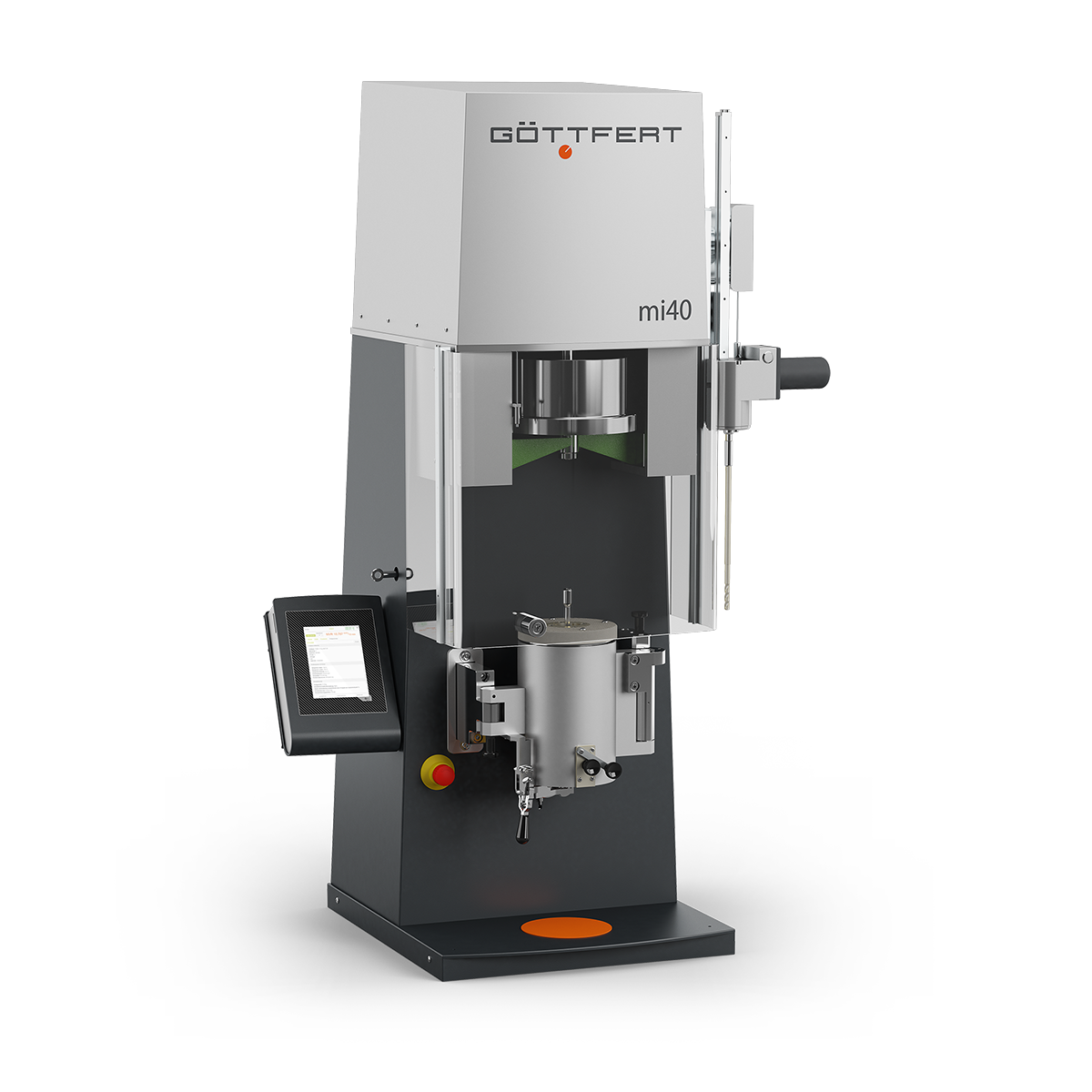
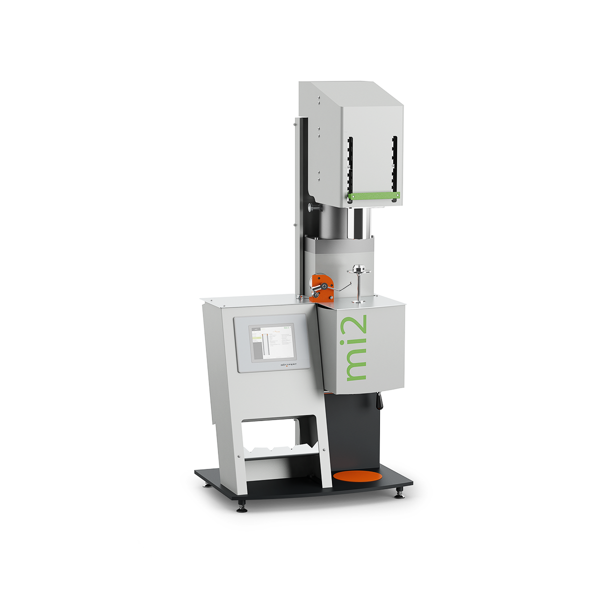
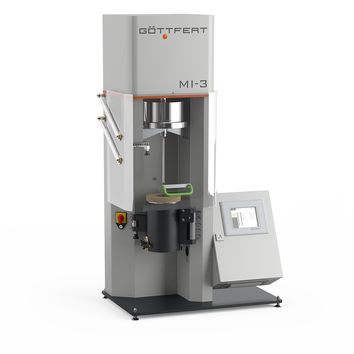
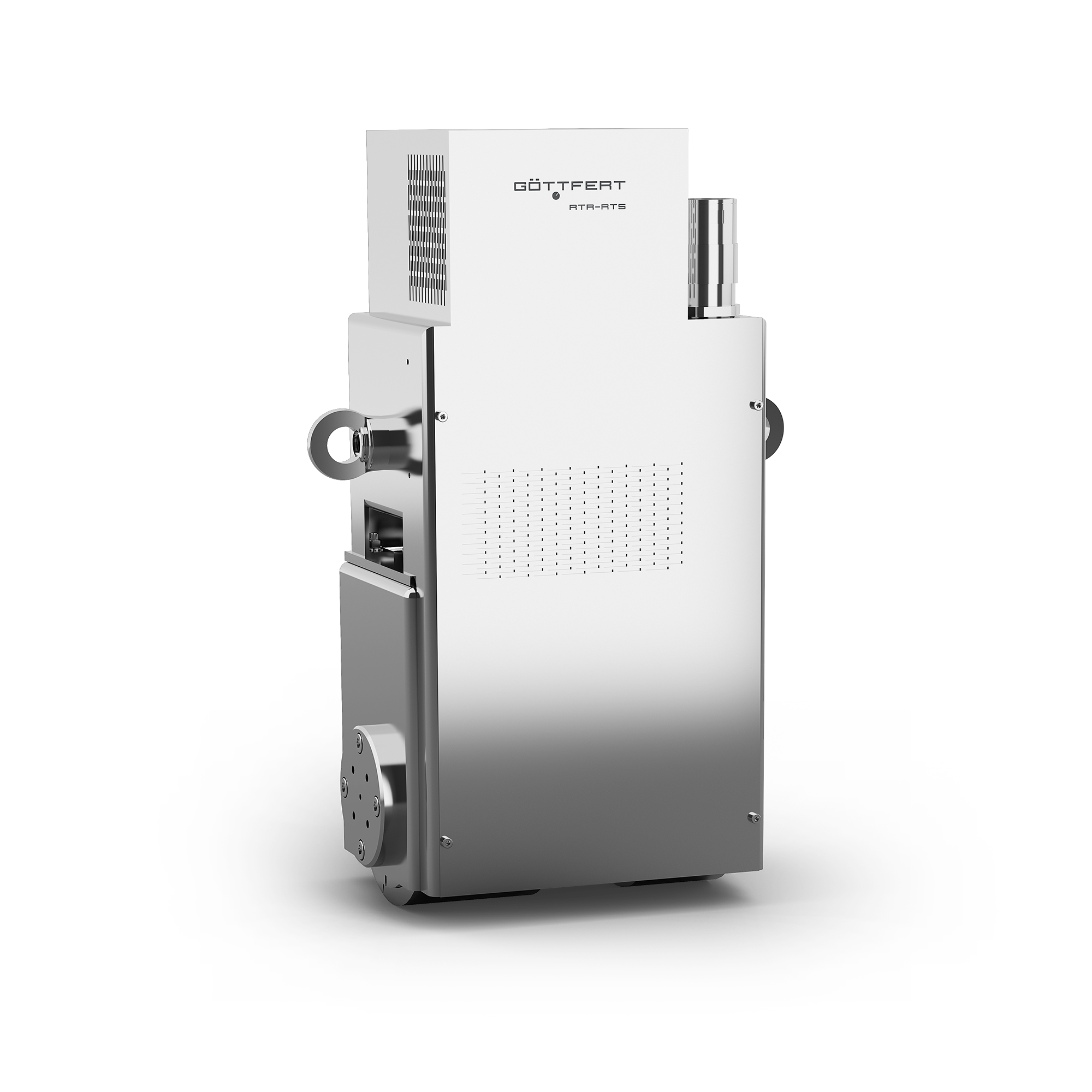
德国Goettfert(高特福)公司于1962年制造出世界上第一台毛细管流变仪。四十多年来,其设计制造的熔融指数仪系列的世界用户占有率最高,它的优异的加工精度和设计理念使得仪器的使用寿命最长
世界用户情况:
几乎所有世界著名的公司或研究单位都有Goettfert的熔融指数仪,如杜邦、拜耳、DOW化学、巴斯夫、GE、壳牌、大众、塞科等等,从第一台熔融指数仪到现在,约有几千台仪器在使用。
国内用户情况:
几乎所有国内的石化企业和研究单位都有Goettfert的产品,如北京石油化工研究院、茂名石化、上海塞科、南京扬子石化、兰州石化、大庆石化、GE广州、巴斯夫(上海)公司、燕山石化、上海富士施乐、齐鲁石化等等。
智能文字提取功能测试中
ISO 1133-1:2011(E) INTERNATIONALSTANDARD ISO 1133-1 First edition2011-12-01 Plastics一 Determination of the meltmass-flow rate (MFR) and melt volume-flow rate (MVR) of thermoplastics - Part 1: Standard method Plastiques-Determination de lindice de fluidite a chaud desthermoplastiques, en masse (MFR) et en volume (MVR)- Partie 1: Methode normale ISO 1133-1:2011(E) COPYRIGHT PROTECTED DOCUMENT C ISO 2011 All rights reserved. Unless otherwise specified, no part of this publication may be reproduced or utilized in any form or by any means,electronic or mechanical,including photocopying and microfilm, without permission in writing from either ISO at the address below or ISO'smember body in the country of the requester. ISO copyright officeCase postale 56·CH-1211 Geneva 20Tel.+4122 749 01 11Fax + 41 22 749 09 47E-mail copyright@iso.orgWeb www.iso.org Published in Switzerland Copyright Intemational Organization for Standardizatior Provided by IHS under license with ISONo reproduction or networking permitted witwlithout license from IHS Contents Page Foreword... ...iv Introduction........... .....V 1 Scope..... 1 2 Normative references .... 1 3 .Terms and definitions....... 1 4 Principle....... 2 5 Apparatus.... 3 Extrusion plastometer...... 3 Accessory equipment ....... .7 6 Test sample........ 8 6.1 Sample form....... .8 6.2 Conditioning.. 8 7 Temperature verification, cleaning and maintenance of the apparatus .... 9 7.1 Verification of the temperature control system...... 7.2 Cleaning the apparatus........ .. 7.3 Vertical alignment of the instrument...... 8 Procedure A:mass-measurement method.... ..10 8.1 Selection of temperature and load .... ..10 8.2 .Cleaning....... ..10 8.3 Selection of sample mass and charging the cylinder... ..10 8.4 Measurements .......... ..11 8.5 Expression of results ...... ......12 9 Procedure B: displacement-measurement method ..... ..13 9.1 . Selection of temperature and load .... ..13 9.2 Cleaning....... .13 9.3 Minimum piston displacement distance..... ..13 9.4 Selection of sample mass and charging the cylinder..... ..13 9.5 .Measurements... ..113 9.6 Expression of results...... ..14 10 .Flow rate ratio...... ....15 11 Precision........ ..16 12 Test report ..... ...16 Annex A (normative) Test conditions for MFR and MVR determinations..... ....18 Annex B (informative) Conditions specified in International Standards for the determination of the meltflow rate of thermoplastic materials.... .19 Annex C (informative) Device and procedure for preforming a compacted charge of material bycompression... ....20 Annex D (informative) Precision data for polypropylene obtained from an intercomparison of MFR andMVR testing........ .23 Bibliography....... . 2 4 Nat far Resale Foreword ISO (the International Organization for Standardization) is a worldwide federation of national standards bodies(ISO member bodies). The work of preparing International Standards is normally carried out through ISOtechnical committees. Each member body interested in a subject for which a technical committee has beenestablished has the right to be represented on that committee. International organizations, governmental andnon-governmental, in liaison with ISO, also take part in the work.ISO collaborates closely with the InternationalElectrotechnical Commission (IEC) on all matters of electrotechnical standardization. International Standards are drafted in accordance with the rules given in the ISO/IEC Directives, Part 2. The main task of technical committees is to prepare International Standards. Draft International Standardsadopted by the technical committees are circulated to the member bodies for voting. Publication as anInternational Standard requires approval by at least 75 % of the member bodies casting a vote. Attention is drawn to the possibility that some of the elements of this document may be the subject of patentrights. ISO shall not be held responsible for identifying any or all such patent rights. ISO 1133-1 was prepared by Technical Committee ISO/TC 61, Plastics, Subcommittee SC 5, Physical-chemicalproperties. This first edition of ISO 1133-1 cancels and replaces ISO 1133:2005. It also incorporates the TechnicalCorrigendum, ISO 1133:2005/Cor.1:2006. In this part of ISO 1133,changes have been made to accommodate ISO 1133-2. In addition:Clause 3 includesfurther definitions relevant to both parts of ISO 1133; 5.1.3 specifies the lower edge of the piston head; 5.1.4updates temperature tolerances; 5.2.1.7 on a preforming device has been added; 5.2.2.2 includes revisedcut-off timing accuracy; 8.3 provides cut-off time intervals that are consistent with other specifications in thispart of ISO 1133; 8.5.3 and 9.6.3 have been included on expression of half die results; 9.3 provides minimumpiston displacements that are consistent with other specifications in this part of ISO 1133; Annex B has beensimplified to avoid inconsistencies between this and the materials specification standards; Annex C, has beenadded for the preparation of charges of material that is particularly suited to testing flake or other large aspectratio particles; Annex D has been added to provide precision data from an intercomparison on a high MVR/MFRmaterial. This part of ISO 1133 applies to melt flow rate testing broadly equivalent to that of ISO 1133:2005. ISO 1133-2applies to the testing of polymers that are rheologically sensitive to the time-temperature history to which theyare subjected during melt flow rate testing. ISO 1133 consists of the following parts, under the general title Plastics-Determination of the melt mass-flowrate (MFR) and meltvolume-flow rate (MVR) of thermoplastics: Part 1: Standard method — PFart 2: Method for materials sensitive to time-temperature history and/or moisture Introduction For stable materials that are not rheologically sensitive to the time-temperature history experienced during meltflow rate testing, this part of ISO 1133 is recommended. For materials whose rheological behaviour is sensitive to the test’s time-temperature history, e.g. materialswhich degrade during the test, ISO 1133-2 is recommended. NOTE At the time of publication, there is no evidence to suggest that the use of ISO 1133-2 for stable materialsresults in better precision in comparison with the use of this part of ISO 1133. INTERNATIONAL STANDARD Plastics- Determination of the melt mass-flow rate (MFR) andmelt volume-flow rate (MVR) of thermoplastics 一 i Part 1: Standard method WARNING - Persons using this document should be familiar with normal laboratory practice, ifapplicable. This document does not purport to address all of the safety problems, if any, associatedwith its use. It is the responsibility of the user to establish appropriate safety and health practices andto ensure compliance with any regulatory requirements. 1Scope This part of ISO 1133 specifies two procedures for the determination of the melt mass-flow rate (MFR) andthe melt volume-flow rate (MVR) of thermoplastic materials under specified conditions of temperature andload. Procedure A is a mass-measurement method. Procedure B is a displacement-measurement method.Normally, the test conditions for measurement of melt flow rate are specified in the material standard with areference to this part of ISO 1133. The test conditions normally used for thermoplastics are listed in Annex A. The MVR is particularly useful when comp01aring materials of different filler content and when comparing filledwith unfilled thermoplastics. The MFR can be determined from MVR measurements, or vice versa, providedthe melt density at the test temperature is known. This part of ISO 1133 is also possibly applicable to thermoplastics for which the rheological behaviour isaffected during the measurement by phenomena such as hydrolysis (chain scission), condensation and cross-linking, but only if the effect is limited in extent and only if the repeatability and reproducibility are within anacceptable range. For materials which show significantly affected rheological behaviour during testing, thispart of ISO 1133 is not appropriate. In such cases, ISO 1133-2 applies. NOTE The rates of shear in these methods are much smaller than those used under normal conditions of processing,and therefore it is possible that data obtained by these methods for various thermoplastics will not always correlate withtheir behaviour during processing. Both methods are used primarily in quality control. 2 Normative references The following referenced documents are indispensable for the application of this document. For datedreferences, only the edition cited applies. For undated references, the latest edition of the referenced document(including any amendments) applies. ISO 1133-2, Plastics - Determination of the melt mass-flow rate (MFR) and melt volume-rate (MVR) ofthermoplastics - Part 2: Method for materials sensitive to time-temperature history and/or moisture ISO 4287, Geometrical Product Specifications (GPS) - Surface texture: Profile method - Terms, definitionsand surface texture parameters ISO 6507-1, Metallic materials - Vickers hardness test - Part 1:Test method 3 Terms and definitions For the purpose of this document, the following terms and definitions apply. 3.1 melt mass-flow rate MFR rate of extrusion of a molten resin through a die of specified length and diameter under prescribed conditionsof temperature,load and piston position in the cylinder of an extrusion plastometer, the rate being determinedas the mass extruded over a specified time NOTE MFR is expressed in units of grams per 10 min. Alternative units accepted by Sl are decigrams per minute,where 1 g/10 min is equivalent to 1 dg/min. 3.2 melt volume-flow rate MVR rate of extrusion of a molten resin through a die of specified length and diameter under prescribed conditionsof temperature, load and piston position in the cylinder of an extrusion plastometer, the rate being determinedas the volume extruded over a specified time NOTE MVR is expressed in units of cubic centimetres per 10 min. 3.3 load combined force exerted by the mass of the piston and the added weight, or weights, as specified by theconditions of the test NOTE Load is expressed as the mass, in kilograms, exerting it. 3.4 preformed compacted charge test sample prepared as a compressed charge of polymer sample NOTE In order to introduce samples quickly into the bore of the cylinder and to ensure void-free extrudate, it may benecessary to preform samples originally in the form of, for example, powders or flakes into a compacted charge. 3.5 time-temperature history history of the temperature and time to which the sample is exposed during testing including sample preparation 3.6 standard die die having a nominal length of 8,000 mm and a nominal bore diameter of 2,095 mm 3.7 half size die die having a nominal length of 4,000 mm and a nominal bore diameter of 1,050 mm 3.8 moisture-sensitive plastics plastics having rheological properties that are sensitive to their moisture content NOTE Plastics which, when containing absorbed water and heated above their glass transition temperatures (foramorphous plastics) or melting point (for semi-crystalline plastics), undergo hydrolysis resulting in a reduction in molarmass and consequently a reduction in melt viscosity and an increase in MFR and MVR. 4 Principle The melt mass-flow rate (MFR) and the melt volume-flow rate (MVR) are determined by extruding moltenmaterial from the cylinder of a plastometer through a die of specified length and diameter under presetconditions of temperature and load. For measurement of MFR (procedure A), timed segments of the extrudate are weighed and used to calculatethe extrusion rate, in grams per 10 min. For measurement of MVR (procedure B), the distance that the piston moves in a specified time or the timerequired for the piston to move a specified distance is recorded and used to calculate the extrusion rate in cubiccentimetres per 10 min. MVR can be converted to MFR, or vice versa, if the melt density of the material at the test temperature isknown. NOTE The density of the melt is required at the test temperature and pressure. In practice, the pressure is low andvalues obtained at the test temperature and ambient pressure suffice. 5 Apparatus 5.1 Extrusion plastometer 5.1.1 General. The basic apparatus comprises an extrusion plastometer operating at a fixed temperature.The general design is as shown in Figure 1. The thermoplastic material, which is contained in a vertical cylinder,is extruded through a die by a piston loaded with a known weight. The apparatus consists of the followingessential parts. 5.1.2 Cylinder. The cylinder shall have a length between 115 mm and 180 mm and an internal diameter of(9,550±0,007) mm and shall be fixed in a vertical position (see 5.1.6). The cylinder shall be manufactured from a material resistant to wear and corrosion up to the maximumtemperature of the heating system. The bore shall be manufactured using techniques and materials that producea Vickers hardness of no less than 500 (HV 5 to HV 100) (see ISO 6507-1) and shall be manufactured by atechnique that produces a surface roughness of less than Ra (arithmetical mean deviation) equal to 0,25 pm(see ISO 4287). The finish, properties and dimensions of its surface shall not be affected by the material beingtested. NOTE 1 For particular materials, it is possible that measurements will be required at temperatures up to 450 ℃. The base of the cylinder shall be thermally insulated in such a way that the area of exposed metal is less than4 cm2, and it is recommended that an insulating material such as Al2O3, ceramic fibre or another suitablematerial be used in order to avoid sticking of the extrudate. A piston guide or other suitable means of minimizing friction due to misalignment of the piston shall be provided. the piston. Reatessive waneneckinpistoneaaana stonaedohe der acd erratic results can be indications ofmisalignmentofis recommended. 5.1.3 Piston. The piston shall have a working length at least as long as the cylinder. The piston shall have ahead (6,35±0,10) mm in length. The diameter of the head shall be (9,474±0,007) mm. The lower edge of thepiston head shall have a radius of(0,4_) mm and the upper edge shall have its sharp edge removed. Abovethe head, the piston shall be relieved to <9,0 mm diameter (see Figure 2). Key insulation 2 removable weight 3 piston 4 upper reference mark 5 lower reference mark 6 cylinder 7 piston head 8 die 9 die retaining plate insulating plate insulation 12temperature sensor Figure 1 - Typical apparatus fordetermining melt flow rate, showing one possible configuration The piston shall be manufactured from a material resistant to wear and corrosion up to the maximum temperatureof the heating system, and its properties and dimensions shall not be affected by the material being tested.To ensure satisfactory operation of the apparatus, the cylinder and the piston head shall be made of materialsof different hardness. It is convenient for ease of maintenance and renewal to make the cylinder of the hardermaterial. Along the piston stem, two thin annular reference marks shall be scribed (30±0,2) mm apart and so positionedthat the upper mark is aligned with the top of the cylinder when the distance between the lower edge of thepiston head and the top of the standard die is 20 mm. These annular marks on the piston are used as referencepoints during the measurements (see 8.4 and 9.5). A stud may be added at the top of the piston to position and support the removable weights, but the piston shallbe thermally insulated from the weights. Not for Resale The piston may be either hollow or solid. In tests with very low loads the piston may need to be hollow,otherwise it may not be possible to obtain the lowest prescribed load. Table 1 一 Dimensions of piston head Length of head,A 6,35±0,10 Diameter of head, B 9,474±0,007 Diameter of stem, C <9,0 Radius of lower edge, R 0,40,001 a Sharp edge removed. Figure 2 Schematic of piston head 5.1.4 Temperature-control system. For all cylinder temperatures that can be set, the temperature controlshall be such that between (10±1) mm and (70±1) mm above the top of the standard die, the temperaturedifferences measured do not exceed those given in Table 2 throughout the duration of the test. NOTE The temperature can be measured and controlled with, for example, thermocouples or platinum-resistancesensors embedded in the wall of the cylinder. If the apparatus is equipped in this way, it is possible that the temperature isnot exactly the same as that in the melt, but the temperature-control system can be calibrated (see 7.1) to read the in-melttemperature. The temperature-control system shall allow the test temperature to be set in steps of 0,1 ℃ or less. Table 2 -Maximum allowable deviation from required test temperaturewith distance and with time over the duration of the test Temperatures in degrees Celsius Testtemperature,T at (10±1)mm above the top surface of the standard die Maximum permitted deviation from the required test temperature: from (10±1) mm to (70±1) mm above thetop surface of the standard die 12575 g/10 min or an MVR >75 cm3/10 min, a half size die of length(4,000 ±0,025)mm and bore diameter (1,050±0,005)mm may be used. No spacer shall be used in thecylinder below this die to increase the apparent length to 8,000 mm. The die of nominal length 8,000 mm and bore of nominal internal diameter 2,095 mm is taken to be thestandard die for use in testing. When reporting MFR and MVR values obtained using a half size die, it shall bestated that a half size die was used. 5.1.6 Means of setting and maintaining the cylinder vertical. A two-directional bubble level, set normal tothe cylinder axis, and adjustable supports for the apparatus are suitable for the purpose. NOTE This is to avoid excessive friction caused by the piston leaning to one side or bending under heavy loads. Adummy piston with a spirit level on its upper end is also a suitable means of checking conformity with this requirement. 5.1.7 Load. A set of removable weights, selected so that the combined mass of the weights and the pistongives the required load to within a maximum permissible error of ±0,5%, are mounted on top of the piston. Alternatively, a mechanical loading device combined with a load cell or a pneumatic loading device with apressure sensor, providing the same level of accuracy as the removable weights, may be used. 5.2 Accessory equipment 5.2.1 General 5.2.1.1 Packing rod, made of non-abrasive material,for introducing test samples into the cylinder. 5.2.1.2 Cleaning equipment (see 7.2). 5.2.1.3 Go/no-go gauge, one end having a pin with a diameter equal to that of the die bore minus the allowedtolerance (go gauge) and the opposite end having a pin with a diameter equal to that of the die bore plus theallowed tolerance (no-go gauge). The pin gauge shall be sufficiently long to check the full length of the die usingthe go gauge. 5.2.1.4 Temperature-calibration device (thermocouple, platinum-resistance thermometerr oriothertemperature-measuring device) for calibration of the cylinder temperature-indicating device. A light-gauge probe-type temperature-measuring device that has a short sensing length and which is calibratedat the temperatures and immersion lengths that are to be used when calibrating the cylinder temperature maybe used. The length of the temperature calibration device shall be sufficient to measure the temperatureat (10 ±1) mm from the top of the die. The temperature calibration device shall have sufficient accuracyand precision to enable verification of the MVR/MFR instrument to within the maximum permissible errors intemperature as specified in Table 2. When used, the thermocouple should be encased in a metallic sheathhaving a diameter of approximately 1,6 mm with its hot junction grounded to the end of the sheath. An alternative technique for verification is to use a sheathed thermocouple or platinum-resistance temperaturesensor inserted into a bronze tip with a diameter of (9,4±0,1) mm for insertion in the bore without materialpresent. The tip shall be designed so that it holds the sensing point of the thermocouple or platinum-resistancetemperature sensor (10±1)mm from the top surface of the standard die when it rests directly on top of the die. A further alternative is to use a rod fitted with thermocouples that would allow it to be used to make simultaneoustemperature determinations at (70±1) mm, (50±1)mm. (30±1) mm and (10±1) mm above the top of thestandard die. The rod shall be (9,4±0,1) mm in diameter so that it fits tightly in the bore. 5.2.1.5 Die plug: A device shaped at one end so that it effectively blocks the die exit and prevents drool ofmolten material while allowing rapid removal prior to initiation of the test. 5.2.1.6 Piston/weight support,of sufficient length to hold the piston, and weights as necessary, so that thelower reference mark is 25 mm above the top of the cylinder. 5.2.1.7 Preforming device. A device for preforming samples, e.g. powders, flakes, film strips or fragments,into a compacted charge, thereby allowing quick introduction of the charge into the cylinder and to ensure void-free filling of the cylinder (see Annex C). NOTE It is possible that there are other options to achieve void-free filling of the cylinder. 5.2.2 Equipment for procedure A (see Clause 8) 5.2.2.1 Cutting tool, for cutting the extruded sample. NOTE A sharp-edge spatula or a rotating cutter blade with either manual operation or motor drive has been found tobe suitable. 5.2.2.2 Timer, with sufficient accuracy to enable cutting of the extruded samples with a maximum permissibleerror of ±1 % of the cut-off time interval used. Forverification, compare the cut-off time intervals with a calibratedtiming device over different time intervals of up to 240 s. NOTE MFRs <5 g/10 min can be measured with the maximum allowed cutting time interval of 240 s. In this case,the maximum permissible error for the cutting time is ±2,4 s. Shorter intervals are allowed, but lead to smaller maximumpermissible errors. MFRs >10 g/10 min require cutting times in the order of a few seconds or less. For 1 s, the requiredmaximum permissible error of the cutting time is ±0,01 s or better. Automatic cutters are recommended for MFR valuesgreater than 10 g/10 min. Where the timing device makes physical contact with the piston or weight, the load shall not be altered by morethan ±0.5 % of the nominal load. 5.2.2.3 Balance, with a maximum permissible error of ±1 mg or better. 5.2.3.3Equipment for procedure B (see Clause 9): Piston displacement transducer/timer This equipment measures distance and time for the piston movement, using single or multiple determinationsfor a single charge (see Table 3). Table 3- Piston distance and time measurement accuracy requirements MFR (g/10 min)MVR (cm3/10 min)a Distancemm Times 0,1 to 1,0 ±0,02 ±0,1 >1,0 to 100 ±0.1 ±0,1 >100 ±0.1 ±0,01 a For multiple measurements using a single charge regardless of the MFR or MVR of the material, the requirements shall be thesame as for MFR> 100 g/10 min or MVR> 100 cm3/10 min. NOTE Compliance with distance accuracy requirements for MFR≤ 1 g/10 min and MVR≤ 1 cm3/10 min also ensurescompliance for MFR> 1 g/10 min and MVR>1 cm3/10 min. Where the displacement measurement device makes physical contact with the piston or weight, the load shallnot be altered by more than ±0,5 % of the nominal load. Where the timing device makes physical contact with the piston or weight, the load shall not be altered by morethan ±0,5% of the nominal load. 6 Test sample 6.1 Sample form The test sample may be in any form that can be introduced into the bore of the cylinder, e.g. granules, strips offilm, powder or sections of moulded or extruded parts. NOTE In order to ensure void-free extrudates when testing powders, it can prove necessary to first compress thematerial into a preform or pellets (see Annex C). The form of the test sample can be a significant factor in determining the reproducibility of results. The form ofthe test sample should therefore be controlled to improve the comparability of inter-laboratory results and toreduce the variability between runs. 6.2 Conditioning The test sample shall be conditioned and, if considered necessary, stabilized prior to testing in accordance withthe appropriate material standard. 7 Temperature verification, cleaning and maintenance of the apparatus 7.1 Verification of the temperature control system 7.1.1Verification procedure It is necessary to verify regularly the performance of the temperature-control system (5.1.4). Verify that thetemperature over time as well as distance conforms to the requirements stated in Table 2, and that the pre-heattime (8.3) is sufficient to obtain stabilization. Set the temperature-control system on the MFR/MVR instrument to the required temperature and allow it tostabilize for not less than 15 min. It is preferable to preheat the calibrated temperature-indicating device to the same temperature as that beingmeasured prior to its insertion into the cylinder. If the cylinder temperature is to be verified using material in the cylinder, charge the cylinder within a periodof 15 s up to at least 100 mm above the top of the standard die with the material to be tested or a materialrepresentative thereof (see 7.1.2), using the same technique as for a test (see 8.3). Within 90 s after completing the charging of the material, introduce the calibrated temperature-indicating device(5.2.1.4) along the wall into the cylinder, immersing it in the material therein until the sensoris (10±1) mm abovethe top surface of the standard die. Immediately, start recording the temperature indicated by the calibratedtemperature-indicating device. Determine the time taken from completion of charging until the temperaturehas stabilized to within the temperature limits specified in Table 2 for (10±1) mm above the top surface of thestandard die. This time period shall not be greater than 5 min. The temperature profile along the cylinder shall be verified similarly. For this, measure the temperatures of thematerial also at (30±1) mm, (50±1) mm and (70±1) mm above the top surface of the standard die. Determinethe time taken from completion of charging until the temperature has stabilized to within the temperature limitsspecified in Table 2 for between (10±1) mm to (70±1) mm above the top surface of the standard die.This timeperiod shall not be greater than 5 min. If the time to reach temperature stabilization to within the temperature limits defined in Table 2 is longer than5 min at any of the set distances above the top surface of the die, this shall be recorded in the test report underitem f)"pre-heating time". It is recommended that when verifying the temperature profile along the cylinder, the measurements are startedat the highest point above the die. An alternative technique for verification of the temperature accuracy to within the specification of Table 2 is touse a sheathed thermocouple or platinum-resistance temperature sensor with tip diameter of (9,4±0,1) mm forinsertion in the cylinder without material present. Another technique is to use a piston fitted with thermocouplesat heights of (70±1) mm, (50±1) mm, (30±1) mm and (10±1) mm above the top surface of the standarddie when inserted completely into the cylinder and which fits the bore closely. This configuration allowssimultaneous verification of the temperature with both time and distance. If the instrument is found to be out of specification (Table 2) then it shall be re-calibrated and verified prior touse. 7.1.2NMaterial used during temperature verification It is essential that the material used during verification be sufficiently fluid to permit the calibrated temperature-measuring device to be introduced without excessive force or risk of damage. A stable material with an MFR ofgreater than 45 g/10 min (2,16 kg load) at the verification temperature has been found suitable. If such a material is used for verification purposes in place of a more viscous material that is to be tested, thedummy material shall have a thermal diffusivity similar to that of the material to be tested, so that warm-upbehaviour is similar. It is necessary that the quantity charged for verification be such that, when the calibratedtemperature sensor is subsequently introduced, the appropriate length of the sensor stem is immersed for accurate temperature measurement. This can be checked by inspecting the upper edge of the material coatingof the end of the calibrated temperature sensor, removing the sensor from the cylinder if necessary. 7.2CCleaning the apparatus WARNING- The operating conditions may entail partial decomposition of the material under test orany material used to clean the instrument, or cause them to release dangerous volatile substances, aswell as presenting the risk of burns. It is the responsibility of the user to establish appropriate safetyand health practices and to ensure compliance with any regulatory requirements. The apparatus, including the cylinder, piston and die, shall be cleaned thoroughly after each determination. The cylinder may be cleaned with cloth patches. The piston shall be cleaned while hot with a cotton cloth. Thedie may be cleaned with a closely fitting brass reamer, high-speed drill bit of 2,08 mm diameter, or woodenpeg. Pyrolytic cleaning of the die in a nitrogen atmosphere at about 550 ℃ may also be used. Take care thatthe cleaning procedure used does not affect the cylinder and die dimensions or surface finish. Abrasives ormaterials likely to damage the surface of the piston, cylinder or die shall not be used. The die bore shall be checked with a go/no-go gauge after cleaning. When cleaning the cylinder, piston and dies, take care that any effect the cleaning process and cleaningmaterials, e.g. solvents and brushes, may have on the next determination is negligible, e.g. ensure that they donot appreciably accelerate degradation of the polymer. 7.3 Vertical alignment of the instrument Ensure that the bore of the equipment is properly aligned in the vertical direction. 8 Procedure A: mass-measurement method 8.1 Selection of temperature and load Refer to the material specification standard for testing conditions. If no material specification standard existsor where MVR or MFR test conditions are not specified therein, use an appropriate set of conditions fromTable A.1 based on knowledge of the melting point of the material or processing conditions recommended bythe manufacturer. 8.2CCleaning Clean the apparatus (see 7.2). Before beginning a series of tests, ensure that the cylinder and piston have beenat the selected temperature for not less than 15 min. 8.3 Selection of sample mass and charging the cylinder Charge the cylinder with 3 g to 8 g of the sample according to the anticipated MFR or MVR (see Table 4).During charging, compress the material with the packing rod (5.2.1.1) using hand pressure. Ensure that thecharge is as free from air as possible. Complete the charging process in less than 1 minute. The preheat timeof 5 min begins immediately after charging of the cylinder has been completed. NOTE 1 Variations in the packing pressure used to compress the material in the cylinder can cause poor repeatabilityof results. For the analysis of materials of similar MFR or MVR, the use of the same mass of sample in all tests reducesvariability in the data. NOTE 2 For materials susceptible to oxidative degradation the effect of trapped air on results can be particularlysignificant. Immediately put the piston in the cylinder. The piston may be either unloaded or preloaded with the test weightor, for materials with high flow rates, a smaller weight. If the MFR or MVR of the material is high, i.e. morethan 10 g/10 min or 10 cm/10 min, the loss of sample during preheating is appreciable. In this case, use an Copyright International Organization for StandardizatiorProvided by IHS under license with ISODNo reproduction or networking permitted without ficense from IHS Not for Resale unloaded piston or one carrying a smaller load during the preheating period. In the case of very high melt flowrates, a weight support should preferably be used and a die plug may be necessary. During the preheating time, check that the temperature has returned to that selected, within the limits specifiedin Table 2. To minimize the risk of burns from hot material coming out of the die rapidly, it is recommended that heat-resistant gloves be worn during the removal of the die plug. Table 4 - Guidelines for experimental parameters MFR (g/10 min)MVR (cm3/10 min)a Sample mass in cylinderbce Extrudate cut-off time intervall >0.1 but≤0.15 3 to 5 240 >0,15 but <0,4 3 to 5 120 >0,4 but ≤1 4 to 6 40 >1 but ≤2 4 to 6 20 >2 but ≤5 4 to 8 10 >5d 4 to 8 5 a It is recommended that a melt flow rate should not be measured if the value obtained in this test is less than 0,1 g/10 min (MFR)or 0,1 cm/10 min (MVR). MFRs >100 g/10 min should only be measured using a standard die if the timer resolution is 0,01 s andprocedure B is used. Alternatively, the half size die may be used with procedure A (see 5.1.5).b When the density of the material is greater than 1,0 g/cm, it may be necessary to increase the mass of the test sample. Use thelow mass values for low-density materials. c Sample mass is a significant factor in determining the repeatability of this test and may need to be controlled to 0,1 g to reducevariability between runs. d To achieve sufficient accuracy for an MFR>10 g/10 min, either higher precision of measurement of time, longer cut-off intervalsor procedure B may be required. e When using the half size die a greater amount of material is required to compensate for the reduced volume of the die. Theadditional volume of material required is 0,3 cm3. f These times are consistent with the production of an extrudate length of 10 mm to 20 mm (see 8.4). In operating within thisconstraint, the errors can be significant, particularly for high MFR materials that have short extrudate cut-off times. A reduction inmeasurement errors could potentially be achieved by using larger extrudate cut-off times. The effect of instrumentation resolution onerrors is instrument dependent and can be assessed by performing an uncertainty budget analysis. 8.4 Measurements At the end of the preheat period,i.e. 5 min after completing the charging of the cylinder, in the event that thepiston was unloaded or underloaded during the preheat period, apply the required load to the piston. In theevent that a die plug was used and the piston was unloaded or underloaded during the preheat period, applythe required load to the piston and allow the material to stabilize for a few seconds before removing the dieplug. If a weight support and die plug were both used, remove the weight support first. NOTE It is possible that for some materials shorter preheating times will be required to prevent degradation. For highmelting point, high Tg, low thermal conductivity materials, a longer preheating time can be needed to obtain repeatableresults. Allow the piston to descend under gravity until a bubble-free filament is extruded; this may be achieved beforeor after loading, depending on the actual viscosity of the material. It is strongly recommended that forcedpurging of the sample, done either manually or by using extra weights, before commencement of the test beavoided. If any forced purging is required (i.e. to complete the procedure within the specified time limit), it shallbe finished at least 2 min before the start of the test. Any forced purging shall be carried out within a period of1 min. If forced purging is used, it shall be reported in the test report. Cut off the extrudate with the cutting tool(5.2.2.1) and discard. Continue to allow the loaded piston to descend under gravity. When the lower reference mark on the piston has reached the top edge of the cylinder, start the timer (5.2.2.2)and simultaneously cut off the extrudate with the cutting tool and discard. Collect successive cut-offs in order to measure the extrusion rate for a given time-interval. Depending on theMFR, choose a time interval so that the length of a single cut-off is not less than 10 mm and preferably between10 mm and 20 mm (see cut-off time-intervals in Table 4 and its footnote f as a guide). For low values of MFR (and MVR) and/or materials which exhibit a relatively high degree of die swell, it may notbe possible to take a cut-off with a length of 10 mm or more within the maximum permitted cut-off time-intervalof 240 s. In such cases, procedure A may be used but only if the mass of each cut-off obtained in 240 s isgreater than 0,04 g. If not, procedure B shall be used. Stop cutting when the upper mark on the piston stem reaches the top edge of the cylinder. Discard all cut-offscontaining visible air bubbles. After cooling, weigh individually, to the nearest 1 mg, the remaining cut-offs,preferably three or more, and calculate their average mass. If the difference between the maximum and theminimum values of the individual weighings exceeds 15 % of the average, discard the results and repeat thetest on a fresh portion of the sample. It is recommended that the cut-offs be weighed in order of extrusion. If a continuous change in mass isobserved, this shall be reported as unusual behaviour (see Clause 12). The time between the end of charging the cylinder and the end of the last measurement shall not exceed25 min. For some materials, this time may need to be reduced to prevent degradation or cross-linking of thematerial during the test. In such cases, the use of ISO 1133-2 should be considered. 8.5 Expression of results 8.5.1 General For testing with the standard die, use 8.5.2. For testing with the half size die, see also 8.5.3. 8.5.22Expression of results: standard die The melt mass-flow rate (MFR), expressed in grams per 10 min, is given by the equation MFR(T,mnom)=_6600×m where T is the test temperature, in degrees Celsius; mnom is the mass, in kilograms, exerting the nominal load; 600 is the factor used to convert grams per second into grams per 10 min (600 s); is the average mass of the cut-offs, in grams; is the cut-off time-interval, in seconds. The melt volume-flow rate (MVR) may be calculated from the MFR using the following equation: where p is the density of the melt, in grams per cubic centimetre, and is given by the material specificationstandard or, if not specified therein, obtained at the test temperature (9.6.2). NOTE The density of the melt is required at the test temperature and pressure. In practice, the pressure is low andvalues obtained at the test temperature and ambient pressure suffice. For flow properties, MVR is the preferred measure as it is independent of the melt density (Clause 9). Express the result to three significant figures but with a maximum of two decimal places and record the testtemperature and load used,e.g. MFR=10,6 g/10 min (190℃/2,16 kg), MFR=0,15 g/10 min (190°C/2,16 kg). 8.5.3Expression of results: half size die When reporting results obtained using the half size die the subscript "h" shall be used (see 5.1.5). The MFR and/or MVR are calculated using the equations in 8.5.2. Express the result to three significant figures, but with a maximum of two decimal places, and record the testtemperature and load used,e.g.MFRh=0,15 g/10 min (190°C/2,16kg),MVRh=15,3 cm3/10 min (190°℃/2,16 kg). 9 Procedure B: displacement-measurement method 9.1 Selection of temperature and load See 8.1. 9.2Cleaning Clean the apparatus (see 7.2). Before beginning a series of tests, ensure that the cylinder and piston have beenat the selected temperature for not less than 15 min. 9.3 Minimum piston displacement distance For improved accuracy and repeatability of measurements the minimum piston displacement distances listedin Table 5 are suggested. Table 5 -Guidelines for experimental parameters MVR(cm3/10 min)MFR (g/10 min) Minimum piston displacementmm >0,1 but ≤0,15 0.5 >0,15 but ≤0,4 1 >0.4 but 1 2 >1 but ≤20 5 >20 10 NOTE 1 These values permit at least three measurements to be made for each barrel charge. Operation of theinstrument using values greater than these minimum piston displacements should also lead to reduced measurement errorsdue primarily to the instrument’s displacement resolution. For MVR values less than 0,4 cm3/10 min a maximum time of240 s may result in a further reduction in errors but still permit at least three measurements. The effect of inst9n1rumentationresolution on errors is instrument dependent and can be assessed by performing an uncertainty budget analysis. NOTE 2 For some materials, results can vary depending on the distance moved by the piston. For improved repeatability,it is critical to maintain the same distance moved for individual runs.5. 9.4 Selection of sample mass and charging the cylinder See 8.3. 9.5 Measurements At the end of the preheat period, i.e. 5 min after completing the charging of the cylinder, in the event that thepiston was unloaded or underloaded during the preheat period, apply the required load to the piston. In the event that a die plug was used and the piston was unloaded or underloaded during the preheat period, applythe required load to the piston and allow the material to stabilize for a few seconds before removing the dieplug. If a weight support and die plug were both used, remove the weight support first. NOTE It is possible that for some materials a shorter preheating time will be required to prevent degradation. For highmelting point, high Tg, low thermal conductivity materials, a longer preheating time can be needed to obtain repeatableresults. Allow the piston to descend under gravity until a bubble-free filament is extruded; this may be achieved beforeor after loading, depending on the actual viscosity of the material. It is strongly recommended that forcedpurging of the sample before commencement of the test be avoided. If any forced purging is required, i.e.tocomplete the procedure within the specified time limit, a defined compression load shall be used. Any forcedpurging shall be carried out within a period of 1 min and shall be finished at least 2 min before the start of thetest. If forced purging is used, the compression load and duration shall be reported in the test report. Cut offthe extrudate with the cutting tool (5.2.2.1) and discard. Continue to allow the loaded piston to descend undergravity. When the lower reference mark on the piston has reached the top edge of the cylinder,start the timer (5.2.2.2)and simultaneously cut off the extrudate with the cutting tool and discard. Do not start taking measurements before the lower reference mark on the piston has reached the top edge ofthe cylinder. Measure one of: a) the distances moved by the piston over a predetermined time period; b)the times taken by the piston to move a specified distance. For some materials, results can vary depending on the distance moved by the piston.For improved repeatability,it is critical to maintain the same distance moved for individual runs. Stop the measurements when the upper mark on the piston stem reaches the top edge of the cylinder. The time between the end of charging the cylinder and the last measurement shall not exceed 25 min. Forsome materials, this time may need to be reduced to prevent degradation or cross-linking of the material duringthe test. In such cases, the use of ISO 1133-2 should be considered. 9.6 Expression of results 9.6.1 General For testing with the standard die, use 9.6.2. For testing with the half size die, use 9.6.3. 9.6.2Expression of results: standard die The melt volume-flow rate (MVR), expressed in cubic centimetres per 10 min, is given by the equation MVR(T,mnom)=4x600xl where T is the test temperature, in degrees Celsius; m1nom is the mass, in kilograms, exerting the nominal load; A is the mean of the nominal cross-sectional areas of the cylinder and the piston head, in squarecentimetres and is equal to 0,711 cm2 (see Note 1); Not for Resale 600 is the factor used to convert cubic centimetres per second into cubic centimetres per 10 min(600s); 7 is the predetermined distance moved by the piston or the mean value of the individual distancemeasurements, in centimetres (see 9.3,9.5); 7 is the predetermined time of measurement or the mean value of the individual time measurements,in seconds (see 9.3,9.5). NOTE 1 Due to the tolerances permitted on the cylinder and piston diameters, the mean of the actual cross-sectionalILareas of thee c(ylinder and the piston head varies by less than ±0,5 %. This effect is considered negligible and for simplicityof operation the nominal value of 0,711 cm2 is used. The melt mass-flow rate (MFR), expressed in grams per 10 min, is given by the equation: where the symbols given above apply and p is the density, in grams per cubic centimetre, of the melt at the testtemperature given by the equation: in which m is the mass, in grams,determined by weighing, of extrudate expelled by a piston movement of l cm. NOTE 2 It is possible that a value for density is specified in the material specification standard. NOTE 3 The density of the melt is required at the test temperature and pressure. In practice,the pressure is low andvalues obtained at the test temperature and ambient pressure suffice. Express the result to three significant figures but with a maximum of two decimal places, and record thetest temperature and load used, e.g. MVR= 10,6 cm3/10 min (190 ℃/2,16 kg), MVR=0,15 cm3/10 min(190℃/2,16 kg). 9.6.3EExpression of results: half size die When reporting results obtained using the half size die, the subscript symbol"h" shall be used (see 5.1.5). The MFR and/or MVR are calculated using the equations in 9.6.2. Express the result to three significant figures but with a maximum of two decimal places, and record thetest temperature and load used, e.g. MVRh=0,15 cm3/10 min (190 °C/2,16 kg) or MFRh = 15,0 g/10 min(190°C/2,16 kg). 10 Flow rate ratio The ratio of two values of MFR (or MVR) obtained for a material tested at the same temperature but withdifferent loads is called the flow rate ratio (FRR), e.g. MFRR=-FR (190℃/10,0kg)MFR (190℃/2,16kg) NOTE The FRR is commonly used as an indication of the way in which the rheological behaviour of a thermoplasticis influenced by the molecular mass distribution of the material. For the conditions to be used for the determination of the FRR, refer to the appropriate material standards. If nomaterial standard exists or if no FRR test conditions are specified in the material standard, the test conditionsshould be agreed between the interested parties. Express results to two significant figures, or three if both the MFR or MVR values are expressed to three.For the FRR obtained using the half size die, the symbol FRRh shall be used. 11 Precision Consideration shall be given to the factors that may influence the magnitude of the measured values and maylead to a decrease in repeatability. Such factors include: a) thermal degradation or cross-linking of the material, causing the melt flow rate to change during thepreheating or test period (powdered materials requiring long preheating times are sensitive to this effectand, in certain cases, the inclusion of stabilizers is necessary to reduce the variability); b) the length, distribution and orientation of the filler in filled or reinforced materials may affect the melt flowrate. The precision of the method is not known because interlaboratory data are not available. A single precisionstatement would not be suitable because of the number of materials and the wide range in the test parameterscovered. However, earlier data indicated a coefficient of variation of about ±10 % could be expected betweenlaboratories and ±5 % within a laboratory. More recent data on one high flow rate polypropylene grade arepresented in Annex D. 12 Test report The test report shall include at least the following information: a) a reference to this part of ISO 1133 (ISO 1133-1:2011); b) all details necessary for the complete identification of the test sample, including the physical form of thematerial with which the cylinder was charged; c) the details of pre-treatment conditions, including drying and preforming conditions and, where applicable,the precompression load and time used for forced purging prior to measurement; d) the details of any stabilization (see 6.2); e) the temperature and load used in the test; the pre-heat time used (when a value other than 5 min was used); g) for procedure A, the masses of the cut-offs and the cut-off time-intervals, or for procedure B, the predetermined time of measurement or distance moved by the piston and thecorresponding measured values of the distance moved by the piston or the time of measurement; h) the melt mass-flow rate (MFR), in grams per 10 min, or the melt volume-flow rate (MVR), in cubic centimetres per 10 min, expressed to three significant figuresbut with a maximum of two decimal places. When more than one melt flow rate value has been obtained from a single cylinder charge, the mean valueshall be reported as the melt flow rate. All individual values shall also be reported and identified as such; if appropriate, where an MFR or MVR value has been calculated using the melt density in accordance with8.5.2 or 9.6.2 and is reported in the test report, it shall also be stated that the value has been calculated.Report the value of density used for the conversion; Not for Resale j) when reporting MFR and/or MVR values obtained using the half size die, the subscript "h"shall be used,and the fact that a half size die was used shall be stated: k) if appropriate, the flow rate ratio (FRR); a report of any unusual behaviour of the test sample, such as discoloration, sticking and extrudate distortion(sharkskin) or unexpected variation in melt flow rate; n)the date of the test. Annex A (normative) Test conditions for MFR and MVR determinations The conditions used shall be as indicated in the appropriate material specification standard. Table A.1 indicates test temperatures and loads that have been found useful. Other test conditions not listedhere may be used, if necessary, for a particular material. Table A.1 一 Test conditions for MFR and MVR determinations Test temperature, T,℃ 100 125 150 190 200 220 230 235 240 250 260 265 275 280300 Nominal load (combined), mnom, kg 0.325 1,20 2.16 3,80 5.00 10,00 21,60 It is recommended that the temperatures and loads listed be used for new thermoplasticmaterials where material standards either do not exist or do not specify such testingconditions. Any combination of temperature and load may be used. However, the choiceof temperature and load should be based on the rheological properties of the material. NOTE For the code-letters that were presented in versions up to ISO 1133:2005 to describespecific combinations of temperature and load for testing and as used in material designationscodes, the user is referred to ISO 1133:1997. codes, the user is referred to ISO 1133:1997. Annex B (informative) Conditions specified in International Standards for the determination ofthe melt flow rate of thermoplastic materials Testing conditions for materials can be found in the relevant materials specification standards, e.g. those listedin Table B.1. Table B.1 一 Conditions specified in International Standards for the determination of the melt flowrate of thermoplastic materials Materials International Standard(see Bibliography) ABS ISO 2580 ASA, ACS, AEDPS ISO 6402 E/VAC ISO 4613 MABS ISO 10366 PBa ISO 8986 ISO 15494 ISO 15876 PC ISO7391 PEa ISO 1872 ISO 4427 ISO 4437 ISO 15494 ISO 22391 PMMA ISO 8257 POM ISO 9988 PPa ISO 1873 ISO 15494 ISO 15874 PS ISO 1622 PS-I ISO 2897 SAN ISO 4894 a Melt density values for this material may be included in the material standard. ht international Organization tor standardization ghts reserved Annex C (informative) Device and procedure for preforming a compacted charge of material bycompression C.1 General This annex provides information on a method found suitable for preforming a compacted charge of material.This preforming of samples is particularly useful when determining the MFR and MVR of materials suchas powders, flakes, strips of film, or fragments. Preforming such samples into compacted charges reducesproblems associated with air entrapment and voids that lead to poor repeatability of results and permit quickintroduction of the samples into the MFR/MVR cylinder. Other methods of preforming a charge of material maybe suitable. C.2 Principle Powders, flakes, strips of film, or fragments of moulded products are preformed by compression under vacuuminto a compacted charge whose diameter is close to, but not more than, the internal diameter of the cylinder ofthe melt flow rate instrument. The temperature at which the material is compressed should be below the meltingtemperature, Tm, for semi-crystalline polymers and near the glass transition temperature, Tg, for amorphouspolymers, in order to minimize air-entrapment without incurring excessive thermal degradation. C.3 Apparatus C.3.1 General. The apparatus should consist of a heatable cylinder that is closed at the bottom by an endplug. Pressure should be exerted on the material in this cylinder by a piston. Figure C.1 shows an example ofsuch equipment. The apparatus consists of the essential parts detailed in C.3.2 to C.3.6. NOTE The use of apparatus of different design is allowed,e.g. a modified melt flow rate instrument. C.3.2 Steel cylinder. The steel cylinder should be fixed in a vertical position and suitably insulated foroperation up to 300℃. The cylinder length should be between 115 mm and 180 mm and an internal diameter(9,550±0,025)mm. An end plug closes the bottom of the cylinder by use of a plug-retaining nut. C.3.3 Piston. A piston whose working length is at least as long as the cylinder. The piston should have a headof (6,35±0,1) mm in length. The diameter of the piston head should be (9,474±0,007) mm. C.3.4 Heating and thermostatic devices. Heating and thermostatic devices should be used such thatthe selected temperature of the material in the cylinder can be maintained to within ±3,0 C of the requiredtemperature. C.3.5 Load. The loading force exerted on the top of the piston should be (2±0,5) kN and can be applied byany suitable means,e.g. mechanical, pneumatic. This is applied to preform the sample into a compacted chargeand to extrude the charge from the cylinder after removal of the end plug. C.3.6 Vacuum pump. A vacuum pump should be used to remove or reduce moisture and gases entrapped inthe material prior to, during and after preforming to prevent further contamination. 20 C.4 Conditionina Materials shall be conditioned as necessary prior to forming into a compacted charge in accordance with theappropriate materials specification standard. See also clauses on conditioning of the material as appropriate(6.2 and ISO 1133-2). C.5 Compaction procedure Set the cylinder temperature to 10 ℃ to 20°℃ below the melting temperature, Tm, for a semi-crystalline sampleand to 10 °C to 20°C below the glass-transition temperature, Ta, for an amorphous sample.Other temperatureranges may be used if these values are found not to be appropriate but should be below Tm for semi-crystallinematerials or below To for amorphous materials. NOTE 1 The specified temperature ranges have been found to be appropriate for a range of materials. Powders andflakes are only partially softened and compressed under vacuum into a compacted charge. Clean the cylinder and the piston with cloth patches. Close the bottom of the cylinder using the end plug. Charge the cylinder with the conditioned sample. The amount used should not be less than that required forMVR/MFR testing of the material: see Table 4 for guidelines on minimum amount required for testing. Duringcharging, compress the material using a packing rod. In the case of materials with low bulk density, fill thecylinder with a smaller quantity, compress, and repeat until the cylinder is charged with the required amount. Vacuum should be applied to the charge of material, provided it is not prohibited by the material specificationstandard. NOTE 2 The use of vacuum can be used to improve compaction of the material and to minimize moisture uptake by thematerial. Immediately after charging the cylinder apply a force of (2,0±0,5)kN to the piston and hold for 2 min. Remove the piston load. After removing the end plug, extrude the charge from the cylinder by lowering thepiston. C.6 Handling of compacted charge The compacted charge shall be cooled down prior to MFR or MVR testing, unless otherwise specified in theappropriate material specification standard. Key air-cylinder 2 piston 3 vacuum device with seal to cylinder 4 piston head 5 cylinder 6 end plug 7 heater 8 temperature sensor 9 insulation Figure C.1一Example of apparatus for preforming a compacted charge by compression Precision data for polypropylene obtained from an intercomparison ofMFR and MVR testing The results of an intercomparison of melt mass flow rate (MFR) and melt volume flow rate (MVR) measurementson a high melt flow rate polypropylene using testing conditions of 2,16 kg and 230 °℃ carried out in 2007(Reference [21]) are presented in Table D.1. It is emphasized that the material tested was a high melt flow ratematerial and thus the precision obtained for it is unlikely to be representative of the method at all melt flow rates.The precision of the method is also very material dependent. The results of only one laboratory for MVR werediscarded as being outliers. Table D.1 -Intercomparison results on a high melt flow rate polypropylene Method Number oflaboratoriesparticipating Mean value ofMFR or MVR Standarddeviation,s,% Within laboratory Repeatabilitylimit, r (2,8s,)% BetweenI Standard deviation, sR% laboratories Reproducibilitylimit, R (2.8 sR)% MFR 8 43,4 g/10 min 2.2 6,2 7.4 20.8 MVR 16 59.3 cm3/10 min 1,6 4.5 3,7 10.5 Note that these values give a ratio of MFR to MVR of 731,8 kg/m3, compared with the value of 738,6 kg/m3specified in ISO 1873-2 for calculating the mass flow rate from the volume flow rate, a difference in values of1%. Bibliography ( [1] ISO 1133:1997, P lastics - De t ermination of the melt mass-flow ra t e (MFR) and the melt vo l ume-flowrate (MVR) of thermoplastics1) ) ( [21 ISO 1622 (all p arts), Plastics - Polystyrene (PS) moulding an d extrusion mate r ials ) ( [3] ISO 1872 ( a ll parts), Plastics - Polyethylene (PE) moulding and extrusion materials ) ( [4] ISO 1873 (all parts) , Plastics - Polypro py lene (PP) moulding and extrusion materials ) ( [5] ISO 2580 ( a ll parts) , Plastics - Acrylonitrile-butadiene-styrene (ABS) moulding and extrusion materials ) [6] ISO 2897 (all parts), Plastics - Impact-resistant polystyrene (PS-/) moulding and extrusion materials [7] ISO 4427 (all parts), Plastics piping systems - Polyethylene (PE) pipes and fittings for water supply [8] ISO 4437, Buried polyethylene (PE) pipes for the supply of gaseous fuels - Metric series -Specifications ISO 4613 (all parts), Plastics - Ethylene/vinyl acetate (E/VAC) moulding and extrusion materials ( ISO 4894 (all p arts), Plastics - S tyrene/acrylonitrile (SAN) moulding and extrusion ma t erials ) ( ISO 6402 (all p arts), Plastics -Acrylonitrile-styrene-acrylate (ASA),acrylonitrile-(ethylene-propyle ne -diene)-styrene ( AEPDS) an d acr y lonitrile-(chlorinated polyethylene)-styrene ( ACS) m o ulding andextrusion materials ) ( ISO 7391 (all parts) , Plastics- Polycarbonate (PC) moulding and extrusion materials ) ( ISO 8257 ( a ll parts), Plastics - Poly(methyl methacrylate) (PMMA) moulding and extrusion materials ) ( ISO 8986 ( a ll parts) , Plastics - Polybutene-1 (PB-1) moulding and extrusion materials ) ( ISO 9 988 (all parts), Plastic s - Polyoxymethylene (POM) moulding and extrusion m aterials ) ( ISO 10366 (all parts), Plastics - Methyl methacrylate-acrylonitrile-butadiene-styrene (MABS) mouldingand e xtrusion materials ) ( [17] ISO 15494,Pl a stics piping systems for industrial applications - P olybutene (PB), po l yethylene (PE)and polypropylene (PP)- S pecifications for c omponents and the system - Metric series ) ( ISO 15874 (all parts), Plastics piping systems for hot and cold water installations - Po ly p rop ylen e (PP ) ) ( ISO 1 5 876 (all parts), Plastics p iping systems for hot and co l d water installations- Pol y b utylene (PB) ) ( ISO 22391 (a l l parts), P lastics piping s ystems f o r hot and cold water installations -Polyethylene ofraised temperature resistance (PE-RT) ) [211 RIDES, M., ALLEN, C.,OMLOO, H., NAKAYAMA, K., CANCELLI, G. Interlaboratory comparison of melt flowrate testing of moisture sensitive plastics.Polym. Test. 2009, 28, pp. 572-591 1) Superseded. ISO 1133-1:2011(E) ICS 83.080.20 Price based on 24 pages Reference numberISO E)O ISO ot for Resale O ISO -All rights reservedNot for Resale
关闭
-
1/32
-
2/32
仪尊科技有限公司为您提供《ISO1133 塑料-热塑性塑料熔体质量流动速率MFR和熔体体积流动速率MVR的测定标准》,该方案主要用于中检测,参考标准《暂无》,《ISO1133 塑料-热塑性塑料熔体质量流动速率MFR和熔体体积流动速率MVR的测定标准》用到的仪器有德国高特福熔融指数仪/熔体流动速率仪MI40、德国高特福熔融指数仪/熔体流动速率测定仪、德国高特福熔融指数仪/熔体流动速率测定仪MI-3、德国高特福在线流变仪。
我要纠错


 咨询
咨询