方案详情文
智能文字提取功能测试中
6AA v号 人 Ermittlung vonthermodynamischen Potenzialenalternativer Zuindsystemean einem strahlgefuhrten Brennverfahren .1o Nn Determination ofThermodynamic Potentialsfor Alternative lgnition Systemsi.Cuin Spray-Guided Combustion M. FeBler, Dr. M. Wetzel,Dr. M. Schenk, Dr. H. Rottengruber, W.HuhnBMW AG, Miinchen 1 Einleitung Schwerpunkt der aktuellen und zukunftigen Entwicklungsvor-haben auf dem Gebiet der Verbrennungsmotoren ist die deutlicheAbsenkung des Kraftstoffverbrauchs bei gleichzeitiger Reduzie-rung der Schadstoffemissionen. Die BMW Group verfolgt hierbeidie Umsetzung des Prinzips ,,Effiziente Dynamik", der gleichzeiti-gen Optimierung von Kraftstoffverbrauch,Leistung und Gewicht.Sehr groBes Potenzial um dieses Ziel zu erreichen bietet bei otto-motorischen Anwendungen das spraygefuhrte BMW DI Brenn-verfahren [1]. Wesentliche Anforderungen an geschichtete Brennverfahrensind: •Bereitstellung einer kompakten, stabilen, reproduzierbaren undhomogenisierten Gemischwolke am Zundort zum Zundzeitpunkt zuverlassige Entflammung des aufbereiteten Gemisches durchdas Zundsystem Durch die konsequente Weiterentwicklung der Injektortechnolo-gie wurde in den letzten Jahren die Grundlage fur die Entwick-lung des strahlgefuhrten DI-Brennverfahrens geschaffen. Diesesbei BMWzur Serienreife entwickelte Brennverfahren,welches inder neuen Vier- und Sechszylinder-Ottomotorengeneration in deneuropaischen Markten eingefuhrt wurde, ist gekennzeichnetdurch eine enge raumliche Kopplung von Injektor (High PrecisionInjection) und Zundkerze im Brennraum, wie in Abbildung 1 dar- 1 Introduction Current and future developments of the combustion engine servefirst and foremost to significantly reduce both fuel consumptionand harmful emissions. In pursuing this goal, the BMW Group isconsistently implementing the principle of "EfficientDynamics",optimising fuel economy, performance, and weight all at thesame time. Application of the spray-guided BMW DI combustionprinciple in the internal combustion gasoline engine offers thebest potential in achieving this target [1]. The main requirements in a stratified combustion process are: · To provide a compact, stable, reproducible, and homogenisedfuel/air mixture at the place and time of ignition · To reliably ignite the fuel/air mixture prepared through the igni-tion system. Consistent development of injector technology has set the foun-dation in recent years for the development of the spray-guided DIcombustion process. This combustion principle enhanced byBMW to production level and featured in the new generation ofBMW's four- and six-cylinder gasoline engines in the Europeanmarkets, is characterised by the compact arrangement of theinjector (High Precision Injection) and the spark plug in the com-bustion chamber, as shown in Figure 1, and enables to capitaliseon the thermodynamic potential of stratified combustion in anoptimised process [2,3]. gestellt und ermoglicht eine opti-male Umsetzung des thermody-namischen Potenzials derSchichtverbrennung [2,3]. Prinzipbedingt stellt die Entflam-mung bei geschichteten Mager-brennverfahrendiekritischePhase der Verbrennung dar. Sofuhren vor allem die, fur Schicht-brennverfahren typischen star-ken raumlichen und zeitlichenGradienten der Kraftstoffkon-zentration und des Stromungs-feldes in der Funkenstrecke zuhohen zyklischen Schwankun-gen bei der Verbrennungsein-leitung. Vor dem Hintergrund On account of the principleapplied, the critical phase in thecombustion process with strati-fied lean-burn combustion is thepoint of inflammation. Particu-larly the significant spatial andtime-related gradients in theconcentration of fuel and theflow field to be covered by thespark in stratified combustionlead to substantial cyclical fluc-tuations in initiating the combus-tion process. With exhaust gaslegislation becoming increa-singly strict and with growingdemand for a significant reduc-tion of fuel consumption by new einer sich weiter verscharfenden Abgasgesetzgebung und denzunehmenden Forderungen nach einer deutlichen Absenkungdes Kraftstoffverbrauchs von Neufahrzeugen, werden sich dieAnforderungen an das strahlgefuhrte Brennverfahren und insbe-sondere an das Zundsystem nochmals erhohen. So stellt aus heu-tiger Sicht das konventionelle Zundsystem einen limitierendenFaktor bei der Darstellung zukunftiger verbrauchsarmer Motor-konzepte mit hohen Restgasraten und Aufladung dar. Ziel der durchgefuhrten Untersuchungen war es, den Einfluss desZundsystems auf das Entflammungsverhalten und den weiterenBrennverlauf zu untersuchen. Hierzu wurden die Entflammungs-eigenschaften eines konventionellen Induktivzuindsystems mitdenen eines Laserzundsystems verglichen.Als Versuchstragerkam sowohl ein thermodynamischer Einzylinder-Forschungs-motor, als auch ein Transparentmotor zum Einsatz. Die Heraus-forderung bei dieser Untersuchung stellte insbesondere dieErfassung der Flammkernbildung und der Entflammungsphasedar. Zu diesem Zweck wurde eine optische Analyse mittelsFlammenkonturplot-Auswertung gewahlt, die den Vergleich derZundsysteme ermoglicht. vehicles, the requirements made of the spray-guided combustionsystem and, in particular, the ignition system will become evengreater and stricter in future. From today's perspective, there-fore, the conventional ignition system is a limiting factor in theintroduction of low-emission engine concepts for the future withhigh rates of residual gas and turbocharger technology. The studies conducted and described in this paper examine theinfluence of the ignition system on inflammation behaviour andthe ongoing course of the combustion process. For this purposethe inflammation behaviour of a conventional inductive ignitionsystem was compared with the inflammation behaviour of a laserignition system. The test units were a thermodynamic single-cylinder research engine and a transparent engine. The mainchallenge in the study was to determine and monitor the forma-tion of the flame core and the inflammation phase. An opticalanalysis was conducted for this purpose by way of a flame con-tour plot allowing a comparison of ignition systems. 2 Versuchsaufbau und Methoden 2.1 Motor fuir thermodynamische Untersuchungen Die im Folgenden beschriebenen Untersuchungen erfolgten aneinem thermodynamischen 4-Takt-Einzylinder-Forschungsmotor,dessen Geometrie auf den aktuellen BMW Vier-und Sechszylin-der-Motoren mit Benzindirekteinspritzung der zweiten Genera-tion und Schichtladung basiert. Aufgrund der Zielsetzung, die kritische fruhe Entflammungsphasebeim strahlgefuhrten Schichtbrennverfahren genauer zu untersu-chen und einen Vergleich der Entflammungsgute verschiedenerZundsysteme zu ermoglichen, war eine Modifikation desSerienzylinderkopfes notwendig. So verfugt der hier verwendeteZylinderkopf uber zwei Zundkerzenbohrungen, welche symme-trisch zum nach auBen offnenden Piezo-Injektor zentral imBrennraumdach angeordnet sind. Durch eine so genannteLangsanordnung von Injektor und der Zundsysteme parallel zurKurbelwellenachse des Motors, konnte eine geometrisch voll-kommen identische Zundsystem-Injektor-Zuordnung fur beideZundungszugange in den Brennraum realisiert werden. DieseZylinderkopfkonfiguration bietet somit die Moglichkeit, einendirekten Vergleich von zwei verschiedenen Zundsystemen imMotorbetrieb darzustellen, ohne einen Systemwechsel vorneh-men zu mussen. Weiterhin verfugt der Motor uiber variable Nockenwellen Pha-sensteller (VANOS) auf der Ein- und Auslassseite. DasVerdichtungsverhaltnis betrug e =12. Fur die Untersuchungenwurde handelsubliches Benzin Super Plus (ROZ=98) als Kraftstoffverwendet. In Tabelle 1 sind die wichtigsten Motordaten zusam-mengefasst. 2 Test array and methods 2.1 Engine for thermodynamic studies The studies described in the following were conducted on athermodynamic four-stroke single-cylinder research enginebased in its geometry on BMW's current four- and six-cylinderengines with second-generation direct gasoline injection andstratified charge. Given the objective to examine the critical early phase of inflam-mation in the spray-guided stratified combustion process withgreater precision and to compare the inflammation quality ofvarious ignition systems, it was essential to modify the cylinderhead with respect to the series production engine. Hence, thecylinder head used here comes with two spark plug bores arran-ged symmetrically to the outward opening piezo-injector in themiddle of the combustion chamber roof. A longitudinal arrange-ment of the injector and the ignition systems parallel to thecrankshaft axis of the engine allowed for both ignition feeds anidentical arrangement in geometric terms with respect to theinjector. This configuration of the cylinder head therefore offersthe possibility to directly compare two different ignition systemsin the actual operation of the engine without having to switchover from one system to the other. The engine also features variable camshaft phase adjusters(VANOS) on both the intake and outlet valves. The compressionratio was e = 12. The fuel used in the tests was commerciallyavailable premium plus quality (RON=98). Table 1 presents thekey data of the engine. Apart from conventional measuring technology on the test stand Tabelle 1:Motordaten und Indiziermesstechnik Neben der konventionellen Pruf-standsmesstechnik zur Erfassungder integralen Messdaten desMotors, wie statische Drucke,Temperaturen und der Abgaszu-sammensetzung wurde zusatzlicheine zeitlich hoch aufgelosteIndizierung der Drucke im Brenn-raum, Ansaug- und Abgastraktdurchgefuhrt. Die Hoch- und Nie-derdruckindizierung idient alsBasis fur eine spatere Druckver-laufsanalyse, welche Aussagenuber die Energieumsetzung im Table 1:Engine data and indicated measuring technology Motor 1-Zylinder Forschungsmotor Hubraum 499 ccm Bohrung 84 mm Hub 90mm Verdichtungsverhaltnis 12 Ventilzahl 4 Ventilhub Nockenwellensteller 9,9 mm auf Ein- und Auslassseite Verstellbereich 80 KW auf Ein-und Auslass Abgasruckfuhrsystem Externe Abgasruckfuhrung mit AGR-Ventil Einspritzsystem Benzin-DI, Piezo-Injektor, zentrale Einbaulage Zundsystem 120mJ Induktiv- und Laserzundsystem Hochdruckaufnehmer Kistler 6061-B(piezo-elektrisch) Niederdruckaufnehmer Kistler 4045 A2 (piezoresistiv)+Kuhladapter Indiziersystem AVL Indimaster Advanced 671 (16 Messkanale) serving to determine and recordthe integral measuring data of theengine such as static pressure,temperatures and the composi-tion of exhaust gases, pressurereadings i the combustionchamber, the intake and outletducts were also conducted witha high level of time resolution.Such measurement of the highand low pressure indicated ser-ves as the basis for subsequentanalysis of the pressure curve,providing information on the con-version of energy in the combus- 2.2 Transparentmotor Der Transparentmotor basiert auf der Geometrie des thermody-namischen Einzylinder-Versuchsmotors. Er besitzt groBflachigeoptische Zugange aus Quarzglas im Kolbenboden und im oberenTeil der Laufbuchse. Die geschlitzte und verlangerte Ausfuhrungder Laufbuchse und des Kolbens bietet die Moglichkeit derBeobachtung und der Beleuchtung mittels einer schwingungs-entkoppelten, lichtstarken Spiegeloptik. Die obersten 44 mm derLaufbuchse sind durch einen Quarzring ersetzt. Die Kompres-sionsringe des Kolbens sind entsprechend zuruckversetzt. Beiden hier durchgefuhrten Versuchen erfolgte eine entlang derZylinderachse integrierte Aufnahme der Flammen-Chemilu-mineszenz und der Diffusionsverbrennung (RuBeigenleuchten)durch das Kolbenbodenfenster. Uber den Quarzglasring wurde 2.2 Transparent engine The transparent engine is based on the geometry of the thermo-dynamic single-cylinder test engine. Optical access is providedbe means of quartz glass window in the piston bow/ and a quartzcylinder, substituting the upper 44 mm of the liner. An elongatedopen-slit liner/piston arrangement offers a large aperture opticalaccess by means of mirrors. This access can be used both fordetection and illumination purposes. The compression rings inthe piston are set back appropriately. In the tests conducted the flame chemiluminescence and thediffusion combustion process (soot glow) were recorded throughthe window in the bottom of the piston along the axis of the cylin-der. Illumination of the combustion chamber was ensured mittels einer kontinuierlichenLichtquelle die Beleuchtung desBrennraumsrealisiert. Hier-durch konnte eine geometrischeKorrelation der Gemischbildung,der Verbrennung und der Brenn-raumgeometrie erzielt werden.Das KKolbenbodenfenster miteinem Durchmesser von 40,6 mmbietet eine optische Apertur, diein etwa 25% der Kolbenquer-schnittsflache entspricht. Diesbietet optimale Voraussetzungenzur Beobachtung des Entflam-mungsverhaltens verschiedenerZundsysteme. Fur die optischenUntersuchungen kam ein aroma-tenfreier Multi-Komponenten-Kraftstoff zum Einsatz, welcherin seiner Siedelinie dem Otto-kraftstoff angepasst ist. Dieserbietet den Vorteil einer sehrgeringen Eigenfluoreszenz undreduzierter RuBbildungsnei-gung. Ein schematischer Aufbaudes Transparentmotors ist inAbbildung 2 dargestellt. Abbildung 2:Schematische Darstellung des TransparentmotorsFigure 2:Schematic view of the transparent engine through the quartz glass ring bymeans of a continuous lightsource. This allowed geometriccorrelation of the fuel/air mixingprocess, of the combustion pro-cess and the geometry of thecombustion chamber. Measuring 40.6 mm in diameter,the window in the bottom of thepiston offers an optical aperturerepresenting approximately 25%of the piston cross-section. Thisprovides optimum conditions forobserving the inflammationbehaviour of various ignitionsystems. The optical experiments wereconducted with a multi-compo-nent fuel with its boiling lineadapted to that of gasoline andwithout aromatic components,offering the advantages of mini-mumfuel-fluorescence andreduced soot formation. A sche-matic overview of the transpa-rent motor is presented in Figure2. 2.3 Ziindsysteme Auf Basis des strahlgefuhrten Brennverfahrens wurde dasPrinzip der Laserzundung mit dem einer konventionellen Gleit-funkenzundung verglichen. Schwerpunkt der Untersuchungenstellt dabei die Bewertung des Entflammungsverhaltens dar. As-pekte sind hierbei unter anderem Bauteil-Quenching, Interaktionmit der Ladungsbewegung und Einfluss des Zundortes. In diesenBereichen verspricht das Zundprinzip des Lasers deutlicheVorteile. Vorangegangene Untersuchungen zeigten die prinzipielleRealisierbarkeit der Laserzundung fur ottomotorische Anwen-dungen. Hierzu wird der Strahl eines kurzen Laserpulses aufeinen Brennpunkt fokussiert. Ab Leistungsdichten in derGroBenordnung von etwa 10 - 100 GW/cm2 entsteht durchMehrquantenionisation ein ,,optischer" Gasdurchbruch. Das soentstandene Plasma absorbiert die im Weiteren einfallende Applying the spray-guided combustion process, the study com-pared the principle of laser ignition with that of conventional sur-face gap spark ignition. Main emphasis of the tests was put onthe evaluation of the inflammation behaviour, focusing on aspectssuch as component quenching, interaction with the chargemotion,and the influence of the location of ignition. Especially inthese respects the laser ignition principle promises significantbenefits. Previous studies had already proven laser ignition to be in prin-ciple suitable to ignite an internal combustion gasoline engine.For this purpose the beam of a short laser pulse is focused on aspecific point. Above power densities of approximately 10 -100GW/cc, multi-quantumionisation occurs and results in an opticalgas breakdown. The so formed initial plasma absorbs during therest of the laser pulse duration the laser energy. This leads to a Energie des Laserpulses. Dies fuhrt zueiner raschen Aufheizung und Expansiondes Laserplasmas, dessen Schockwel-len als deutlich horbarer Knall wahr-nehmbar sind [4]. Die Einkopplung des Laserlichtes in denBrennraum erfolgte uber die Zundker-zenbohrung.DieFokussierunggdesLaserstrahls wurde mittels einer plan-konvexen Saphirlinse mit einer opti-schen Apertur von 6 mm realisiert. DieStrahleinkopplung in den Brennraumzeigt die folgende Abbildung 3. Eine Variation des Zundortes im Brenn-raum entlang der Strahlachse erfolgte Abbildung 3: Brennraumgeometrie mit LaserstrahleinkopplungFigure 3: Geometry of the combustion chamber with laser beam feed quickly heating up and expanding of theplasma with shock waves to be heardclearly as an audible "bang"[4]. Laser light is fed into the combustionchamber via the spark plug bore and thelaser beam is focused by a plane-con-vex sapphire lens with an optical aper-ture of 6 mm. Figure 3 displays the laserbeam and its access to the combustionchamber. The point of ignition within the combus-tion chamber was varied along the sprayaxis by changing the focal length (f=17-25 mm) and, respectively, by usingcopper gaskets of various dimensions. Abbildung 4:Uberblendung von Laserplasma und KraftstoffwolkeFigure 4: Superposition of the images of laser plasma and fuel spray Das Referenzzundsystem bildet ein Hochenergie-Induktivsystemmit einer 120mJ Kompaktzundspule und einer fur den geschichte-ten Motorbetrieb optimierten Dreihaken-Gleitfunkenzundkerze. 2.4 Methodenentwicklung fur optischeEntflammungsuntersuchung Ziel war es, durch eine geeignete Methodik den Einfluss desZundsystems auf das Entflammungsverhalten und die -stabilitatzu untersuchen. Die Herausforderung stellte besonders dieErfassung der Flammenkernbildung und der Entflammungsphasein hoher zeitlicher und ortlicher Auflosung dar. Aus diesem Grund kam neben der klassischen Druckindizierungvorwiegend ein optisches Analyseverfahren zum Einsatz. Hierzuwurde der in Abschnitt 2.2 beschriebene ,,optische Motor" inKombination mit einem Highspeed-Kamerasystem (HighSpeed-Star 5, Fa. LaVISION) eingesetzt. Dies ermoglicht zeitlich hochaufgeloste, lichtstarke Aufnahmen der fruhen Entflammungs-phase durch den Glaskolbenboden. Bei der Auswertung derRohdaten wurde neben der Darstellung der Aufnahmen alsHighspeed-Videofilm, besonders nach einer Auswerte- undVisualisierungsmethodik gesucht, welche die, in den Rohdatenenthaltenden Informationen bezuglich der Entflammung undFlammenausbreitung vollstandiger und optimierter veranschau-licht. Anforderungen waren hierbei: ·Visualisierung der sich ausbildenden Flammenfront. · Flammenausbreitung uber mehrere Zeitschritte (°KW) soll ineiner Abbildung dargestellt werden, um schnelle Aussagenuiber GroBe, Richtung und Geschwindigkeit der Flammenaus-breitung zu erhalten. · Verbesserung des Signal/Rausch-Verhaltnisses und Ausgleichvon schwankender Aufnahmequalitat (z.B. hervorgerufen durchVerschmutzung), um direkten Vergleich verschiedener Zund-systemvarianten zu ermoglichen. Als Darstellungsform, welche all diese Anforderungen erfullt,wurde der so genannte Multikontur-Plot gewahlt. Dazu wird ausden Rohdaten die GroBe und Lage der Flammenflache bei ver-schiedenen Grad KurbelwinkeIn ermittelt (Binarisierung). An-schlieBend werden die Hullkurven der zu verschiedenen Zeit-schritten ermittelten Flachen in einem Diagramm ubereinandergelegt und farbig gekennzeichnet. Dieses Auswerteverfahren The reference ignition system is a high-energy induction systemwith a 120mJ compact ignition coil and surface gap spark plugwith three ground electrodes, optimised for stratified operationconditions. 2.4 Development of a method for opticalexamination of the inflammation process The purpose of the study was to examine the influence of theignition system on inflammation behaviour and the stability of theinflammation process by taking an appropriate methodologicalapproach. The main challenge was to record the formation of theflame kernel and the inflammation phase with a high level of tem-poral as well as spatial resolution. Hence optical measurement techniques were primarily applied inaddition to the conventional indication of pressure. The transpa-rent engine described in Section 2.2 was used for this purpose incombination with a high-speed camera system (HighSpeedStar 5by LaVISION). This provides high-speed, light-intense imaging ofthe early inflammation period through the piston window. Besidesprocessing the images as a movie, main emphasis in assessingand evaluating the camera images was to find an evaluation andvisualisation method, capable of visualising the inflammation andearly flame propagation in a quality optimisedmanner and ascompletely as possible. The requirements were: · To visualise the spreading flame front. · To present the propagation of flame at various timings (CA) ina single picture in order to obtain simultaneously information onthe size, direction and rate of flame propagation. · To improve the signal-to-noise ratio and reduce or avoid theimpact of fluctuations in signal quality (caused, for example,bywindow fouling), in order to obtain a direct comparison ofdifferent ignition systems. The mode of presentation chosen to fulfil all these requirementswas the so-called multi-contour plot. To obtain the plot, the sizeand position of the flame area is determined from the raw imagesat various crank angle positions (binarisation). After that theenveloping curves of the areas determined at different crankangles are presented as an overlay plot with the colour varyingwith the crank position. This evaluation process may be appliedto individual images within one cycle, to averaged images, aswell as to the images representing the cyclic variation (RMS kann sowohl auf Einzelzyklusbilder, auf gemittelte Bilder, als auchauf die Standardabweichung aus mehreren Arbeitsspielen (RMS-Bild) angewendet werden. Letzteres ist vor allem zur Bewertungder Flammenstabilitat von Zyklus zu Zyklus besonders geeignet.Die Darstellungsform des Multikontur-Plots ist bereits aus demkommerziellerhaltlichen optischen ILichtleitermesssystemVisioTomo@ der Fa. AVL bekannt. Bei diesem System wird jedoch,im Gegensatz zu den hier prasentierten Messungen, die 2D-Flammenausbreitung in der Zylinderkopfdichtungsebene mittelsLichtleitertomographie erfasst [5]. Fur die hier im Mittelpunkt ste-hende Untersuchung des ersten Entflammungsprozesses und derFlammenkernbildung war jedoch eine integrative Erfassung derFlammenausbreitung von Noten. Mit dem hier verwendetenHighspeed-Kamerasystem konnte eine Abtastung von bis zu20 kHz, bei einer Ortsauflosung im Beobachtungsfenster von ca.70k Pixel (durch 9x9-Filterung, ca. 900 Pixel im Konturplot) erfol-gen. Die hier verwandte Beobachtungsperspektive uber denKolbenboden integriert die Ausbreitung der Flamme dabei uiberdie gesamte Brennraumtiefe in Richtung der Zylinderachse. 3 Ergebnisse 3.1 Optische Analyse des Entflammungsverhaltens Im folgenden Abschnitt wird ein optischer Vergleich zwischendem Entflammungsverhalten eines konventionellen Induktivzund-systems mit Zundkerze und einem Laserzundsystem vorgestellt.Dabei wurden sowohl Untersuchungen im Homogen-, als auch imSchichtbetrieb durchgefuhrt. Die Analyse erfolgte hierbei in der,in Abschnitt 2.4, beschriebenen Methodik 3.1.1 Homogenbetrieb Die Analyse des Prozesses der Flammkernbildung und die Ver-brennungseinleitung wurde im stochiometrischen Homogen-betrieb bei 2000 U/min und einem indizierten Mitteldruck pmi von4 bar durchgefuhrt. Die weiteren Randbedingungen des Be-triebspunktes sind in Tabelle 2 dokumentiert. Der Zundvorgangder beiden Zundsysteme erfolgte zeitlich synchron im selbenArbeitsspiel um moglichst identische Entflammungsrandbedin-gungen fur die beiden Systeme zu gewahrleisten.Das Analyse-verfahren ermoglichte die separate Visualisierung des Entflam-mungsbeginns der Laserzundung und der konventionellenZundkerze. image). The latter serves in particular to evaluate the stability ofthe flame propagation from cycle to cycle. The visualisation by means of multi-contour plots is already well-known from the AVL VisioTomo@, a fiber-optical measuringsystem commercially available. Unlike the results presentedhere, however, the AVL system determines the 2D flame propa-gation within the plane of the cylinder head gasket by way offiber-optical based emission-tomography [5]. Since our study,however, which is focussed on the initial inflammation processand the formation of the flame kernel, it was considered asessential to depict the flame propagation by recording images,which integrate the flame emissions along the observation axis,i.e. as a projection of the 3D-flame to a 2-D image plane, perpen-dicular to the axis of observation. The high-speed camera systemused in the present study was able to operate up to 20 kHz withspatial resolution within the window of observation of approx 70kpixels (in case of 9x9 filtering, approx 900 pixels). The observationperspective through the bottom of the piston applied here inte-grates flame emissions along an axis parallel to the cylinder axisthroughout the entire depth of the combustion chamber. 3 Results 3.1 Optical analysis of inflammation behaviour The following section presents an optical comparison of theinflammation behaviour of a conventional inductive ignitionsystem with a spark plug and a laser ignition system. Tests werecarried both for the homogeneous and the stratified mode,respectively. The evaluation of the measurements was conduc-ted in accordance with the methodology described in Section 2.4. 3.1.1 Homogeneous operation The process of flame kernel formation and the combustion initia-lisation were analysed for stochiometric homogeneous operationof the engine at 2000 rpm and at an indicated mean effectivepressure IMEP of 4 bar. The detailed operating conditions arestated in Table 2. The ignition process on both ignition systems was initializedsimultaneously within each engine cycle to assure similar inflam-mation conditions for both systems. The evaluation method allo-wed separate analysis and visualisation of the inflammation initi-alized by the laser and the conventional spark plug. Tabelle 2:Betriebsparameter stochiometrischer Homogenbetrieb Die nachfolgende Abbildung 5zeigt den zeitlichen Verlauf desEntflammungsfortschritts ausdem Highspeedfilm eines repra-sentativen Einzelarbeitsspiels.. Auf der linken Bildhalfte sind dieEinbaulage unddas Entflam-mungsverhalten der Gleitfunken-kerze visualisiert. Die rechte Table 2:Operating parameters in the stochiometric homogeneous mode Betriebsart Homogen, a=1 Drehzahl 2000 1/min Last Pmi=4 bar Einspritzparameter EOl=270 KW v. OT Zundzeitpunkt 18 KW v. ZOT zeitliche Auflosung der Kamera 12 kHz (=1 KW pro Bild) Figure 5 presents the inflamma-tion process for various crankangle positions within one typicalengine cycle..The left sidedepicts the mounting positionand inflammation behaviour ofthe surface gap spark plug. Theright side shows the formation ofthe flame kernel near the laser Bildhalfte zeigt die Flammkernbildung nahe des symmetrisch bzgl.des Injektors verbauten Zundkerzenadapters des Laserzuind-systems. Aus der Aufnahme ist deutlich ersichtlich, dass direkt nach derExpansion des Laserplasmas sich bereits ein Entflammungs-gebiet ausbildet. Bei der Zundkerze hingegen dauert es nach demFunkendurchbruch noch einige Grad KW (bis ca. 13 °KW v. OT),bis eine Flammkernbildung wahrgenommen werden kann. DasResultat ist somit ein deutlich schnelleres Flammenwachstum in ignition adapter, which was mounted symmetrically with respectto an intersection plane through the cylinder axis (perpendicularto the crank shaft). The image shows clearly that a flame kernel forms directly afterthe thermal expansion of the laser plasma. In case of the sparkplug a several degrees of crank angle after the spark breakdownare required (up to approximately 13° CA BTDC) until the forma-tion of a flame kernel is observed. der fruhen Verbrennungsphasefur das Laserzuindsystem. Da-ruber hinaus ist erkennbar, dasses durch das frei im Raum situ-ierte Laserplasma zu einer unge-nderten spharischen Flam-menausbreitung kommt. Durchdie Auslenkung des Zundfun-kens und der Interaktion mit denElektroden wird die Flammkern-bildung an der Zundkerze hinge-gen stark beeinflusst. Als Resul-tat zeigt sich eine stark asymme-trische Flammenausbreitung. Es muss hier noch darauf hinge-wiesen werden, dass es durchden extrem hellen und intensi-ven optischen Durchbruch beider Laserzuindung zu einer Uber-blendung des CMOS-Chips derHighspeed-Kamera kommt. DiePixel, welche den Bereich desexpandierenden Plasmas auflo-sen, gehen dadurch fur einigeMillisekunden in Sattigung. DasheiBt, obwohl die Plasmastand-zeit beim Zundlaser nur in derGroBenordnung von ca. 10 psliegt, ist selbst 14 °KW nachZundzeitpunkt noch der Umrissdes Laserplasmas auf denHighspeed-Bildern zu sehen. Um die Informationen uber dasEntflammungsverhalten der bei-den Zundsysteme aus den High-speed-Videoaufnahmen zu ex-trahieren und eine ausfuhrlicheAnalyse zu ermoglichen, wurdenun die in Abschnitt 2.4 be-schriebene Flammenkonturplot-auswertung angewandt.DerKonturplot in Abbildung 6 zeigthierbei die Auswertung vonMittelwertbildern aus 50 aufein-ander folgenden Arbeitsspielen.Die farbig abgesetzten Hullkur-ven zeigen die raumliche Aus-breitung der Flammenflache inZeitschritten von einem GradKurbelwinkel ab dem Zundzeit-punkt. Diese Darstellungsform veran-schaulicht die Unterschiede imEntflammungsverhalten zwi-schen Zundkerze und Zundlaserbesonders deutlich. So ist derstarke Einfluss der Massenelek-troden auf die Phase der Flam-mkernbildung bei der Zundkerze 6°KW V. OT 5°KW v.OT 4°KW v.OT Abbildung 5:Entflammungsphase aus Highspeed-Videoaufnahme (Einzelzyklus)Figure5: Inflammation phase as presented in a high-speed video (individual cycle) Abbildung 6: Flammenkonturplot fur HomogenbetriebFiqure 6: Flame contour plot in the homogeneous mode an den sehr dicht nebeneinander liegenden Linien derFlammenhullkurven in den ersten 8 °KW nach der Zundung zuerkennen. Es findet in dieser fruhen Verbrennungsphase nur ein The result is much faster flamegrowth in the early combustionphase with the laser ignitionsystem. A further obvious pointis that the laser plasma floatingfreely in space allows unrestric-ted spherical propagation of theflame. The formation of a flamecore on the spark plug, on theother hand, is strongly influen-ced by the deflection of the igni-tion spark and interaction withthe electrodes leading, as aresult, to strongly asymmetricalpropagation of the flame. A point to be emphasised in thiscontext is that the extremelybright and intense optical bre-akthrough in the case of laserignition results in a overexposu-re of the CMOS chip in the high-speed camera. The pixels resol-ving the area of expanding plas-ma are thus saturated for a fewmilliseconds. So although plas-ma life on the ignition laser isonly about 10 ps, the contours ofthe laser plasma are still to beseen on the high-speed imagesat 14° CA after the point of igni-tion. To obtain information on theinflammation behaviour of thetwo ignition systems from thehigh-speed video and to allowdetailed analysis, the next stepwas to conduct a flame contourplot evaluation as described inSection 2.4. In this case the con-tour plot shown in Figure 6 pre-sents the evaluation of meanvalue images from 50 consecuti-ve work strokes. The envelopingcurvespresentedincolourshow the spatial propagation ofthe flame surface in time incre-ments of 1o crank angle startingat the point ofignition. Thismode ofpresentationallowsaparticularly(cleardistinction of inflammation be-haviour between the spark plugand the ignition laser. The signi-ficant influence of the masselectrodes on the phase of flamecore formation on the spark plugis to be seen from the very closelines of the flame envelopingcurves in the first 8°CA afterignition. sehr langsames Wachstum des Flammenkerns statt. Offensicht-lich kommt es an den Massenelektroden zu einem signifikantenQuenching des Flammenkerns. Folglich kann die Expansion derFlamme nur uber den Raum zwischen den Masseelektrodenerfolgen. Im direkten Vergleich mit der Laser-induziertenEntflammung auf der rechten Seite wird der groBe Vorteil desLaserzundprinzips deutlich. Durch den nahezu frei wahlbarenEntflammungsort, fernab umgebender Bauteile, wird eineEntflammung initiiert, die sich nahezu unbeeinflusst im Brenn-raum ausbreiten kann. Durch die schnelle thermische Expansiondes Initialplasmas und dessen kurze Standzeit von wenigen 10 usist auch die Interaktion mit Stromungsfeldern sehr gering. Dasexpandierte Plasma ergibt in Folge ein groBflachiges Entflam-mungsgebiet, das rasch zur spharischen Flammenausbreitung imBrennraum fuhrt. Zum besseren Verstandnis sei darauf hingewiesen, dass dieAussagekraft der hier dargestellten Flammenkonturplots imauBeren Randbereich des optischen Sichtfensters nicht mehrgegeben ist, da die Auswerteroutine bei Erreichen des Sicht-bereiches die geometrische Grenze als Flammenfront interpre-tiert. Wenn die Flammenfront den Rand des Auswertebereichserreicht hat, kann fur den nachsten Zeitschritt in diesem Gebietkeine weitere Aussage uber die Flammenausbreitungsge-schwindigkeit oder die maximale FlammenflachengroBe mehrgetatigt werden, da sich logischerweise alle nachfolgendenFlammenflachen nur maximal bis zum AuBendurchmesser desAnalysebereichs ausdehnen konnen. Da jedoch das Haupt-augenmerk der Untersuchung auf der fruhen Entflammungsphaseliegt,ergibt sich fur unsere Betrachtung keine Einschrankung. Neben der Visualisierung in Form der projizierten 2D-Flammen-konturplots, ist aus den binarisierten Flammenaufnahmen aucheine zeitliche Darstellung der FlachengroBenentwicklung der aufeine Ebene projizierten Flamme moglich. Abbildung Z verdeutlichtin dieser Weise den initialen zeitlichen Verlauf des Flammenfort-schritts des konventionellen Induktivzundsystems und derLaserzundung. Hierfur wurde aus dem oben gezeigten Flammen-konturplot, getrennt fur Laserzundung und Zundkerze, dieFlammenflachengroBe fur die Zeitschritte bis zur Vereinigung derbeiden Flammenfronten extrahiert. Dabei ist ersichtlich, dass esbei dem Laserzundsystem zu einem deutlich schnelleren Anstiegder FlammenflachengroBe kommt. Bei 6 °KW vor ZOT hat dieFlammen-front, welche durch das Laser-plasma erzeugt wurde,bereits mehr als die doppelte Flache im Vergleich zum Flammen-areal der Zundkerze erfasst. In this early phase of combustion the flame core grows onlyveryslowly, the mass electrodes apparently quenching the flame corequite significantly. As a result, the flame is only able to expandthrough the space between the mass electrodes. A direct com-parison with laser-induced inflammation on the right-hand sideshows the significant advantage of the laser ignition principle.With the laser ignition, the place of inflammation can be determi-ned almost freely and without restrictions, far away from any sur-rounding components and the inflammation process initiated isable to spread almost freely and without any external influence inthe combustion chamber. Rapid thermal expansion of the initialplasma and its short lifecycle of just a few 10 ps also keep inter-action with the flow fields to a minimum. The expanded plasmathen forms a large inflammation area and leads to a quick spreadof the flame in the combustion chamber in a spherical shapefront. A point to be made in this context in the interest of clarity is thatthe flame contour plot shown here is no longer meaningful at theouter edges of the optical window, since the evaluation routineinterprets the geometric boundary as the flame front when rea-ching the area of vision. Once the flame front has reached theedge of the evaluation area, therefore, it is no longer possible todetermine the rate of flame propagation or the maximum flamearea for the next time increment in this area, since obviously allsubsequent flame surfaces can only expand at most up to theouter perimeter of the area analysed. But since the study focusesprimarily on the early phase of inflammation, this does not impo-se any restrictions on the present study. Apart from visualising the inflammation process through the 2Dflame contour plot projected, the binarised flame images alsoallow time-related presentation of the area and size of the flameprojectedon one plane. Figure Z thus illustrates the initial processof flame propagation on the conventional inductive ignitionsystem and laser ignition as a function of time. For this purposethe flame area has been extracted for the time increments up tothe unification of the two flame fronts from the flame contour plotpresented above, separa-tely for laser ignition and the sparkplug. This shows that the flame area increases in size much morequickly with the laser ignition system. At 6° CA BTDC the flamefront generated by the laser plasma already covers more thantwice the area of the flame front generated by the spark plug. 3.1.2 Schichtbetrieb Im geschichteten Motorbetriebwurden die Unterschiede desEntflammungsverhaltens amBeispiel des 1Teillastbetriebs-punktes 2000 U/min / 2,7 bar indi-ziertem Mitteldruck untersucht.Die weiteren Betriebsparametersind in Tabelle 3 dokumentiert.Die Flammenkonturplots zeigenwiederum den direkten1 Ver-gleich der Zundsysteme beisimultaner Zundung. Neben derMittelwertauswertung in Abbil-dung 8 links, wird hier zusatzlichdie Konturauswertung des Stan-dardabweichungsbildes der 50 Abbildung 7: Vgl. des Flammenflachenwachstums im stochiometrischen HomogenbetriebFigure 7: Comparison of flame area growth in the stochiometric homogeneous mode 3.1.2 Stratified operation The differences in inflammationbehaviour were examined withthe engine running under strati-fied conditions at a part loadoperating point of 2000 rpm / 2.7bar indicated mean effectivepressure. The other operatingparameters are documentedand set forth in Table 3. Theflame contour plots, in turn, pro-vide a direct comparison of igni-tion systems for simultaneousignition. Apart from evaluationof the averaged images in Figure8 at the left, the contours of thestandard deviation images of 50 Arbeitsspiele (RMS) in Abbildung 8 rechtsdargestellt. Bei der Erstellung des Stan-dardabweichungsbildes wird die Stan-dardabweichung der Intensitatsvertei-lung fur jeden Einzelzyklus ermittelt undanschlieBend die Einzelbilder der Zyklenubereinandergelegt. Da in den Rand-bereichen der Flammenflachen die In-tensitatsunterschiede zwischen Flammeund Brennraum groB sind, eignet sichdiese Auswertung besonders gut, um dasEntflammungsgebiet abzugrenzen. DasRMS-Bild visualisiert somit die Flammen-flache, welche zu einem bestimmten GradKurbelwinkel in mindestens einem derEinzelzyklen erfasst wurde. Im direkten Vergleich des Entflammungs-verhaltens zwischen Homogen-Schichtbetrieb mit Hilfe des Mittwelwert-Flammenkonturplots zeigt sich, der be-reits bekannte und deutliche Unterschiedin der Entflammungsgeschwindigkeit zwi-schen den beiden Motorbetriebsarten. Sokommt es bei der geschichteten Verbren-nung durch die zum Zundzeitpunkt bereitsfettenEntflammungsbedingungen dervorgemischten Gemischwolke, zu einersehr schnellen ersten Verbrennungs-phase. Weiterhin wird bei einer Gegen-uberstellung der Flammkernbil-dung an der Zundkerze ersicht-lich, dass die bei homogenerBetriebsart stark ausgepragtenQuenchingverluste undBeein-flussung der Flammenausbreitungdurch die Elektrodengeometrie, Lastnur in reduziertem MaBe bei dergeschichteten Verbrennung auf-tritt. Eine Erklarung dafur liegt inder durch die spate Schichtein- Abbildung 8: Flammenkonturplot des Mittelwert-(AVG)undStandardabweichungsbildes (RMS) im SchichtbetriebFigure 8: Flame contour plot of the mean value (AVG) and standarddeviation image (RMS) in the stratified mode Tabelle 3:Betriebsparameter geschichteter BetriebTable 3: engine cycles (RMS) are evaluated addi-tionally in Figure 8 at the right. In determining the standard deviationimage, the standard deviation of the ima-ges is calculated for crank angle positionseparately and subsequently the enve-lopes of the resulting images are superim-posed on one another. With the differen-ces in intensity between the flame and theunburned mixture being quite substantialaround the edges of the flame area, thisform of evaluation is particularly well-suited to distinguish and clearly mark thearea of inflammation. The RMS imagethus visualises all the area, which isdetermined in at least one of the indivi-dual cycles as flame area for a specificcrank angle. A direct comparison of inflammationbehaviour in the homogeneous and strati-fied modes using the mean value flamecontour plot shows the significant diffe-rence in the rate of inflammation alreadyestablished between the two modes ofengine operation. In the stratified com-bustion process the rich inflammationconditions in the pre-mixed fuel/air cloudalready prevailing at the time of ignitionmake the initial combustion phase very fast. spritzung induzierten Ladungsbewegung zum Zundzeitpunkt ander Zundkerze. Diese Ladungsbewegung fuhrt zu einer weitrei-chenden und gezielten Zundfunkenauslenkung in den Brennraum[2]. In der RMS-Auswertung in Abbildung 8 rechts wird dieserEffekt besonders deutlich. Die Zundfunkenauslenkung und daswechselnde Uberspringen des Zundfunkens zwischen derMittenelektrode und einer der drei Massenelektroden fuhren zueiner groBen Ausdehnung der Hullkurven bereits nachZundzeitpunkt. Hier simuliert diee1Leuchterscheinung desZundfunkens eine erfolgte Entflammung, was aber an dem nichtvorhandenen Flachenwachstum bisISCca.6°KWnachZundzeitpunkt identifiziert werden kann. Ahnlich wieimHomogenbetrieb zeichnet sich auch im Schichtbetrieb dasLaserzundsystem durch eine sehr homogene, spharischeFlammenausbreitung aus. Besonders die Gegenuberstellung vonMittelwert- und Standardabweichungsdiagramm verdeutlicht,durchdienur relativgeringen .AbweichungeninderFlammenausbreitung beim Laserzundsystem, wie reproduzierbarund mit welch geringen zyklischen Schwankungen hier die fruheVerbrennungsphase ablauft. Ebenso wie im Homogenbetriebfuhrt die Zundung mit dem Laserplasma zu einem beschleunigtenFlammenwachstum. Dies zeigt sich einerseits durch die groBerenFlammenflachen im Vergleich zur Zundkerze beim jeweiligen 12 kHz (=1 KW pro Bild) for this difference is the charge motion at the point of ignition onthe spark plug caused by late injection under stratified condi-tions. This charge motion leads to far-reaching and specificdeflection of the ignition spark into the combustion chamber [2]. The RMS evaluation shown in Figure 8 at the right presents thiseffect very clearly. The deflection of the ignition spark and inter-changing overshoot of the spark between the central electrodeand one of the three mass electrodes leads to greater expansionof the enveloping curves immediately after the ignition point. Inthis case the glow of the ignition spark simulates the inflamma-tion process, which can however be identified by the lack ofgrowth of the area covered up to approximately 6°CA followingthe time ofignition. Like in the homogeneous mode, the laser ignition system ischaracterised by very homogeneous, spherical propagation ofthe flame also in the stratified mode. Particularly a comparison ofthe mean value and standard deviation diagrams shows throughthe relatively small deviations in flame propagation on the laserignition system how reproducibly the early combustion phaseproceeds, with only minor cyclical fluctuations. Like in the homo-geneous mode, ignition with laser plasma expedites the growthand propagation of the flame, as is confirmed, first, by the largerflame areas in comparison to the spark plug at each time incre- Zeitschritt und andererseits durch den groBeren Abstand zwi-schen den Flammenflachenhullkurven Um die hier beschriebenen Effekte und Ergebnisse der Auswer-tung mittels Flammenkonturplot zu quantifizieren und somit einenobjektiven Vergleich zwischen den Zundsystemen und Betriebs-arten zu ermoglichen, wird die KenngroBe Entflammungsgite ment and, second, by the larger distance between the flame areaenveloping curves. In order to quantify the effects and the results of evaluationshown here by means of a flame contour plot, thus providing anobjective comparison of ignition systems and modes ofoperation,the next step is to introduce the inflammation quality criterion Aww(KW) :FlachengroBe (Pixel) aus Mittelwertbild bei ZeitschrittARMS(KW) : FlachengroBe (Pixel) aus RMS-Bild bei Zeitschritt dimensionslose Kennzahl np. Damit wird neben der reinenEntflammungsgeschwindigkeit, auch die beim Schichtbrennver-fahren kritische Entflammungsstabilitat berucksichtigt. In der fol-genden Abbildung 9 ist der zeitliche Verlauf der Entflammungs-gute fur den bereits oben diskutierten Schichtbetriebspunkt dar-gestellt. Anhand der optischen Aufnahmen wurde ein aussage-kraftiger Auswertebereich zur Analyse des Entflammungsvor-gangs definiert. Ausgehend vom Zundzeitpunkt (23 KW v.OT)wurde als Kriterium fur den Beginn des Auswertebereichs diemerkliche Ausbildung eines Flammkerns, nach dem Erloschendes Zundplasmas, bei 20 °KW v. OT gewahlt. Begrenzt wurde derAuswertebereich andererseits durch das Erreichen einer kriti-schen FlammengroBe bei 15°KW v. OT. Bei der Gegenuberstellung der Entflammungsgite zeigt sich,dass zu Beginn der Entflammung bei 20 °KW v. OT der np-Wertfur Zundkerze und Laserzundsystem nahezu identisch sind. Imweiteren Verlauf stagniert die Entflammungsgute bei derZundkerze bis ca. 18°KW v. 0T und steigt dann bis zum Ende desuntersuchten Bereichs deutlich an. Das Laserzundsystem hinge-gen zeigt bis 17 °KW v. OT eine signifikante Zunahme des EG-Wertes und fallt anschlieBend auf niedrigere Werte ab. Imgesamten betrachteten Bereich kann jedoch das Laserzundsys-tem eine deutlich bessere Entflammungsgite aufweisen. DiesesErgebnis deckt sich sehr gut mit den Interpretationen derErgebnisse aus den Flammenkonturplots, so dass mit der KenngroBe nE eine aussage- tion rate as such, this also considers the stability of the inflam-mation process absolutely, which is a critical measure understratified combustion conditions. The following Figure 9 shows the time dependency of the inflam-mation quality for the stratified operation point already discussedin the foregoing. Taking the optical images into account, a mean-ingful area of evaluation for analysing the inflammation processhas been defined. Proceeding from the ignition point (23 CABTDC), the criterion chosen for the starting point in the evaluationarea is the noticeable formation of a flame core following extinc-tion of the ignition plasma at 20 °CA BTDC. The evaluation area islimited, on the other hand, by the achievement of a critical flamesize at 15°CA BTDC. Comparing the quality of inflammation, one finds that upon theinception of inflammation at 20 °CA BTDC the spark plug and thelaser ignition system show virtually identical np values. Then, inthe ongoing course of combustion, the quality of inflammation onthe spark plug stagnates until approximately 18 °CA BTDC, sub-sequently increasing significantly until the end of the area exa-mined. By contrast, the laser ignition system shows a significant in-crease in the np value until 17° CA BTDC and then drops to lowervalues. Throughout the entire area examined, however, the laserignition system shows a significantly better quality of inflamma- kraftige KenngroBe zur Beurtei-lung der Entflammungsgute beimSchichtbrennverfahreneeinge-fuhrt werden konnte. 3.2 ThermodynamischeAnalyse Optische Analyseverfahren eig-nen sich aufgrund ihrer hohenzeitlichen und ortlichen Auflo-sung besonders gut zur Unter-suchunggderEntflammungs-phase. Dennoch konnen auchmit Hilfe der konventionellenthermodynamischenAnalyse,basierend auf einer Druckin- Vgl. der Entflammungsgute im Schichtbetrieb Figure 9: Comparison of inflammation quality in the stratified mode tion. Indeed, this result compliesvery well with the interpretationof results from the flame contourplot, np thus serving as a mean-ingful parameter for assessingthe quality of inflammation in thestratified combustion process. 3.2 Thermodynamicanalysis Given their high degree of reso-lution in terms of both time andspace, optical analyticalmethods are particularly well-suited for examining the inflam-mation? phase.Conventionalthermodynamic analysis basedon pressure indication, however,also provides important know- dizierung, wichtige Erkenntnisse uber den Einflusss desZundsystems auf diese fruhe Verbrennungsphase gewonnenwerden. Im folgenden Abschnitt wird anhand der Ergebnisse ausder Druckverlaufsanalyse [6] die Entflammungsstabilitat der bei-den Zundsysteme miteinander verglichen. Die Versuche wurdenhierfur getrennt fur beide Zundsysteme, also Zundung nur einerZundquelle, durchgefuhrt. Weiterhin soll betrachtet werden,inwieweit der Verlauf der ersten Entflammungsphase (hier als 0-5% Umsatz verstanden) einen kausalen Zusammenhang mit demweiteren Brennverlauf, hier speziell der 0-50% Umsatzdauer auf-weist. 3.2.1 Auswertung der zyklischenVerbrennungsschwankungen Ein wichtiges Kriterium fur die Beurteilung der Stabilitat einerSchichtverbrennung ist die zyklische Schwankung des Verbren-nungsvorgangs. Diese wird ublicherweise durch die relativeStandardabweichung des indizierten Mitteldruckes der Einzel-zyklen charakterisiert, dem sogenannten Variationskoeffizienten.Er beschreibt jedoch lediglich,in welchem MaBe die vom Motorabgegebene Arbeit von Zyklus zu Zyklus schwankt. Das Interesse im Rahmen der Zundungsuntersuchungen liegt nunaber nicht in der gesamthaften Beurteilung des Verbrennungs-vorganges, sondern vielmehr in der Stabilitat der Verbrennungs-einleitung und deren Einfluss dieser Entflammungsphase auf denweiteren Brennverlauf. Hierzu wird fur jeden Einzeldruckverlaufvon 256 Zyklen mittels Druckverlaufsanalyse der 5%- und 50%-Umsatzpunkt der Verbrennungsenergiefreisetzung bestimmt.AnschlieBend werden die Um-satzpunkte der Einzelzyklen an-hand ihrer Haufigkeitsverteilung uber der Zeitachse in Resultats-klassen mit einer Breite von 0,25 °KW eingeteilt. Abbildung 10zeigt die Ergebnisse eines ge-schichteten Betriebspunktes bei2000 U/min und 2,7 bar indizierten Mitteldruck. Die Messungenerfolgten jeweils getrennt fur das Laser- und Induktivzundsys-tem. Obwohl die Zundung in Abbildung 10 fur beide Systeme zeitgleichbei 20 °KW v. OT stattfand, zeichnet sich die Laserzundung durcheine im Mittel deutlich fruhere 5%-Umsatzlage und damit einerschnelleren Entflammung aus. Abbildung 10 zeigt, dass die 5%-Umsatzpunkte fur den Zundlaser um einen Mittelwert von ca. 13°KW v. OT annahernd normalverteilt sind (o=0,5°KW). Es kommtalso durch den zeitlich prazise definierten Laserzundzeitpunkt zueiner von Zyklus zu Zyklus sehr konstanten Verbrennungseinlei- ledge on the influence of the ignition system on this early phaseof combustion. The next section of the study therefore applies the results of apressure curve analysis [6] in order to compare the inflammationstability of the two ignition systems. The tests conducted for thispurpose focused separately on the two ignition systems, that is ineach case ignition from only one source. A further point to beconsidered is to what extent the course of the first inflammationphase (understood here to mean a energy conversion period of 0-5%) relates to the ongoing course of combustion, in this case the0-50% energy conversion period. 3.2.1 Evaluation of cyclical fluctuations in combustion An important criterion for judging the stability of stratified com-bustion is the cyclical fluctuation of the combustion process. Thisfluctuation is generally characterised by the relative root meansquare deviation of the indicated mean effective pressure in indi-vidual cycles, the so-called coefficient of variation (COV).However, this root mean square deviation only describes theextent to which the energy generated by the engine fluctuatesfrom one cycle to the other. The essential point in examining the ignition process, however,isnot to assess the entire process of combustion from beginning toend, but rather to study the stability of the initial combustionphase and the influence of this inflammation phase on the ongo-ing combustion process. For this purpose the 5% and 50% massfraction burned (MFB) points in releasing combustion energy aredetermined by analysing each individual pressure curve of the256 cycles. The next step is to categorise the energy conversionpoints in the individual cycles in accordance with their frequen-cy distribution on the time axis in specific categories of resultscovering a width of 0.25° CA. Figure 10 presents the results of astratified operating point at 2000 rpm and 2.7 bar indicated meaneffective pressure. Separate measurements were conducted ineach case for the laser and inductive ignition systems. Although ignition, as shown in Figure 10, takes place at the sametime with both systems at 20° CA BTDC, laser ignition shows amuch earlier 5% MFB point and, as a result, a faster rate ofinflammation.Fiqure 10 also shows that the 5% MFB points for theignition laser have almost normal distribution (o=0.5°CA/around a mean value of approximately 13° CA BTDC. Hence, theignition point precisely defined in the case of laser ignition ensu-res very consistent initialisation process from one cycle to the tung. Die Zundkerze hingegenhat einen mittleren 5%Umsatzbei ca. 11°KW v. OT. Es soll an dieser Stelle auch aufeine prinzipbedingte Schwachedes Laserzundprinzips fur dengeschichteten Motorbetrieb hin-gewiesen werden. Durch dieextrem kurze Plasmastandzeit(ca. 10ps) und die vermutlichgeringere GroBe des Zundplas-mas, ist das Laserzundprinzipnicht geeignet, das Zuordnungs-toleranzproblem des geschich-teten Motorbetriebs; ZUuent-scharfen. Der Zundlaser istsomit nicht in der Lage, die zykli-schen Schwankungen in der Abbildung 10: Haufigkeitsverteilung der thermodynamischen Umsatzpunkte Figure 10: Frequency distribution of thermodynamic turnover points other. The spark plug, by con-trast, shows its mean 5% turno-ver at approximately 11°CABTDC. A further point to be consideredin this context is that the laserignition principle shows a cer-tain weakness in the case ofstratified operation of the enginefor reasons of its underlyingphilosophy alone: With the plas-ma lifecycle being extremelyshort (approx 10ps) and the igni-tion plasma presumably smallerin its dimensions, the laser igni-tion principle is not in a positionto solve the problem of toleranceallocation arising when running Kraftstoffzusammensetzungq undid des StromungsfeldesSamZundort auszugleichen. Somit kommt es im Schichtbetrieb zusporadischen Zundaussetzern. Die Zundkerze zeigt durch die lange Standzeit (bis zu 2ms) undAuslenkung des Zundfunkens, hingegen ein vollig anderesVerhalten bei der Energieeinbringung und Entflammung desGemisches, was zu einem mehr als doppelt so stark schwanken-den 5%-Umsatzpunkt fuhrt (o=1,2°Kw.). Da hier Zund- undEntflammungszeitpunkt nicht zwangslaufig zusammenfallen, tre-ten trotz eines mittleren 5% Umsatzpunktes bei 11°KW v. OT auchnoch zahlreiche Arbeitsspiele mit verschleppten 5%-Umsatz-punkten bis nach 8°KW v. OT auf. Die Analyse der Haufigkeits-verteilung fur die 50%-Umsatzpunkte (Laser:-7,5±0,9°KW v. ZOT;Zundkerze:-4,6±1,9°KW v.ZOT) zeigt die gleichen Tendenzen, wiesie fur die 5%-Umsatzpunkte beobachtet wurden. Zu bemerkenist auch der um zwei °Kw reduzierte mittlere Zundverzug desLaserzundsystems (bezogen auf den 5% Umsatzpunkten). 3.2.2 Einfluss des Entflammungsverhaltensauf den Brennverlauf Um den Einfluss der Verbrennungseinleitung (0-5%), auf den wei-teren Verlauf der Verbrennung (5-50%) zu verdeutlichen, zeigtAbbildung 11 die Streudiagramme aus den jeweiligen Wertepaa-ren der 5%- und 50%-Umsatzpunkte. Links ist das Laserergebnis,rechts das der Zundkerze abgebildet. Fur das Laserzundsystem zeigt sich eine sehr kompakte Punk-tewolke, welche eine elliptische Form aufweist. Fur die Zund-kerze zeigt sich hingegen bereits eine signifikante, annahernd the engine under stratified conditions. Hence, the ignition laser isunable to set off cyclical fluctuations in the composition of fueland the flow field at the point of ignition. In practice, this meanssporadic misfiring when running in the stratified mode. Through its long lifecycle (up to 2ms), on the other hand, and dueto the deflection of the ignition spark, the spark plug shows com-pletely different behaviour in the transfer of energy and theinflammation of the fuel/air mixture, the 5% MFB point thus fluc-tuating more than twice as much as otherwise (o=1.2°CA).Since in this case the ignition and the inflammation points do notnecessarily coincide, we also find numerous engine cycles withthe 5% MFB point deferred until 8°CA BTDC despite a mean 5%MFB point at 11°CA BTDC. Analysis of the frequency distributionof the 50% MFB points (laser: -7.5±0.9° CA BTDC; spark plug:-4.6±1.9° CA BTDC) shows the same tendencies as alreadyobserved with the 5% MFB points. A further point to be conside-red is the mean ignition delay in the laser ignition system down by2°CA, related again to the 5% MFB points. 3.2.2 Influence of inflammation behaviour on the courseof the combustion process To illustrate the influence of the initialisation process (0-5%) onthe ongoing course of combustion (5-50%), Figure 11 presents thescatter diagrams obtained from the various sets of values at the5% and 50% energy conversion points. The result obtained withlaser ignition is shown on the left, the result obtained with a sparkplug on the right. The laser ignition system shows a very compact cloud at just onepoint, elliptical in shape. The spark plug, by contrast, shows a sig- lineare Abhangigkeit der 50% vonden 5% Umsatzpunkten.Dies deutet darauf hin, dass dieStreuung im 50% Umsatz haupt-sachlich durch die Streuung der5% Umsatzpunkte hervorgerufenwird. Die Streuung im 5-50%Umsatz ist hingegen, bei ersteinmal initiiertem 5% Umsatz,von untergeordneter Bedeutung.Anders ausgeruckt, nach 5%Umsatz ist die Flamme nahezuvollstandig unabhangig von derArt der Entflammungsinitiierung.Um diese Unabhangigkeitsaus-sage bzgl. der Entflammungsini-tiierung statistisch solide auchfur die Laserzundung zu unter-mauern, wurden in Abbildung 12die Streudiagramme aus allen5%- und 50%-Umsatzpunkte-paaren eines Zundhakens fur dieLaserzundung und die Zund-kerze ubereinander gelegt. Be-triebspunkt war der in der Ab-bildung 11 spezifizierte. Da jedereinzelne Zuindzeitpunkt aus den256 Einzelzyklen bestand, wurdeauf dies Weise die statistischeAuswertebasis auf ein Viel-faches erweitert und somit pra-zisiert. Abbildung 11: Streudiagramme fur 5%- und 50%-Umsatz bei gleichem ZundzeitpunktFigure 11: Scatter diagrams for 5% and 50% MFB at the same point of ignition nificant, almost linear depen-dence of the 50% MFB points onthe 5% MFB points, indicatingthat the scatter at 50% MFB isattributable mainly to the scatterof the 5% MFB points. The scat-ter in the 5-50% energy conver-sion range, on the other hand,with only 5% MFB initiated, is oflesser significance. To put it inother words- after 5% energyconversion the flame is almostcompletely independent of theway in which the inflammationprocess is initiated. To confirm in clear statisticalterms that the initiation ofinflammation is indeed indepen-dent also in the case of laserignition, Figure 12 superimposesthe scatter diagrams from all 5%and 50% MFB point sets on anignition timing variations forlaser ignition on the one hand,and the spark plug, on the other.The operating point was as spe-cified in Figure 11. Since eachignition point was made up ofthe 256 individual cycles shown,this approach served to signifi-cantly broaden the basis for sta-tistical evaluation, thus ensuringeven more precise results. Abbildung 12:Streudiagramm fur 5%- und 50%-Umsatz von ZundhakenFigure 12:Scatter diagram for 5% and 50% MFB for a variation in ignition timing Figure 12 shows that the pointcloudss of the two ignitionsystems coincide almost com-pletely with one another, theonly deviation being between 13and 14°CA due to the smallerignition delay on the laser. Thisshows that despite differentbehaviour in the inflammationprocess and the different igni-tion retard times on the two igni-tion systems, the 50% energyconversion point for the opera-ting point considered here is, atleast in an initial approximation,independent of the way in whichthe flame is initiated. The courseof combustion as of the 5% ener-gy conversion point is thereforeindependent in the stratified und wird vielmehr durch die vorherrschenden Brennraumbedin-gungen (Druck, Temperatur, Stromungsfeld, Kraftstoffverteilung)bestimmt. An einem bestimmten Zeitpunkt kleiner 5% Umsatz-fortschritt der Verbrennung verliert somit die Verbrennungsein-leitung (Zundung bzw. Entflammung) ihren Einfluss auf den weite-ren Brennverlauf. Durch den Vergleich der Form und Lage der Punktewolke miteiner Geraden der Steigung eins kann aufgezeigt werden, dass esmit zunehmender Spatverschiebung des 5%-Umsatzes, d.h. ver-zogerter Verbrennungseinleitung, zu einer uberproportionalenVerzogerung des 50%-Umsatzpunktes und somit der gesamtennachfolgenden Verbrennung kommt. So fuhrt ein verzogerter Ent-flammungszeitpunkt zu einer Spatverschiebung der Verbrennungin die Expansionsphase, was wiederum eine Verschleppung derVerbrennung zur Folge hat. 3.2.3 Einfluss des Ziindortes im Schichtbetrieb Einer der groBten Vorteile eines Laserzundsystems ist die nahezufreie Wahl des Zundortes, unabhangig von bauteilbedingtenStorgeometrien im Brennraum. Diese Moglichkeit verspricht vielPotenzial fur das Schichtbrennverfahren, vor allem hinsichtlichder Optimierung von Verbrennungsstabilitat und Brennverlauf. Dies sei hier exemplarisch fur eine Fokuslagenvariation an dembereits vorher betrachteten Teillastpunkt prasentiert (Betriebs-parameter siehe Tabelle 4). Ausgehend von der Funkenlage derkonventionellen Zundkerze (referenziert im Folgenden als relativeFokuslage von 0 mm) wurden verschiedene Fokuslagen mit bis zueiner 8 mm tieferen Einbaulage untersucht (tiefere Fokuslagensind positiv referenziert). Bei den jeweiligen Fokuslagen wurdeder Stabilitatsbereich der Verbrennung durch einen Zundhakenmit einer Zundzeitpunktsvariation in Schritten von 2 °KW er-mittelt. Fur die dem Brennraumdach nachste Fokuslage (0 mm) zeigt sichdabei ein recht kleiner Stabilitatsbereich der Zundung von ledig-lich 6 °KW (Abbildung 13 links). Diese Lage befindet sich im auBe-ren Randbereich des Einspritzstrahls, was nur ein kleinesZeitfenster zur Entflammung eroffnet. Bei der Fokuslage von 1 mmkann das Gemisch hingegen nicht in einem Zundbereich,sondernnur an zwei singularen Zeitpunkten stabil entflammt werden. Zuanderen Zundzeitpunkten treten verstarkt Aussetzer auf. ZurInterpretation dieses Aussetzerverhaltens wurde die Korrelationdes Einspritzfensters mit den Sprayflugzeiten von Injektorspitze mode for a specific place of ignition of the type of inflammation,and is rather determined by the conditions prevailing within thecombustion chamber (pressure, temperature, flow field, distribu-tion of fuel). At a specific point in time below 5% combustion tur-nover, the initiation of the combustion process (ignition or,respectively, inflammation) thus losses its influence on the furt-her course of combustion. Comparing the shape and position of the point cloud with astraight one gradient, we see that with the 5% MFB point beingincreasingly retarded, that is with initiation of the combustionprocess being delayed, the 50% MFB point is retarded to an over-proportional extent, the entire ensuing combustion process beingretarded accordingly. Hence, inflammation at a delayed point intime retards combustion in the expansion phase, slowing downthe process of combustion as a whole. 3.2.3 Influence of the point of ignitionin the stratified mode One of the biggest advantages of a laser ignition system is theoption to choose virtually any place of ignition, regardless ofinterference geometry in the combustion chamber caused by thecomponents used. This offers a great potential for stratified com-bustion, particularly in optimising the stability of the combustionprocess and the course of combustion as such. This advantage is presented here by taking the example of avariation in focus position at the part load point already conside-red (see Table 4 for the relevant operating parameters).Proceeding from the spark position of the conventional sparkplug (referenced in the following as the relevant focal position of0 mm), various focal positions were examined with a point ofinstallation up to 8 mm deeper (deeper focal positions are refe-renced positively). On the respective focal positions, the area ofstable combustion was determined by a variation of the ignitiontiming in increments of 2°CA. In the focus position closest to the roof of the combustionchamber (0 mm) the area of ignition stability is relatively small atjust6° CA (Figure 13. left). This position is at the outer edge of theinjection spray, opening up only a small time window for inflam-mation. In a focal position of 1 mm, on the other hand, the fuel/airmixture may be inflamed not in just one ignition area, but ratherat two singular points in time. At the other ignition timings weobserve an increasing degree of misfiring. Tabelle 4: Betriebsparameter geschichteter Betrieb Table 4:Operating parameters in the stratified mode Betriebsart geschichtet, a=3,2 Drehzahl 2000 1/min Last pm=2,7 bar Einspritzparameter ti=ca.0,27ms,EOl1=23KW v.OT,ti2=0,15 ms,EOl2=18 KW v. OT mas mitten im Kraftstoffeinspritzstrahl fuhrt also dazu, dass dieextrem fetten Bedingungen mit hoher Tropfendichte direkt wah-rend des ,,Vorbeifluges"der Einspritzung am Zundort eine stabileEntflammung nicht zulassen. Fur die ubrigen Fokuslagen zeigtsich mit tiefer werdender Einbaulage eine Tendenz zurVerschiebung der Zundgrenzen in Richtung spat (zum ZOT hin).Die Zundhakenbreite liegt hierbei in einem Bereich von etwa 10°KW und steigt bei der tiefsten Fokuslage (8 mm) sogar auf 12°KW an. Wertet man die Aussetzerrate uber das so erzielte Kennfeld aus,Abbildung 13, so zeigt sich, dass bei den spaten Zundzeitpunktenin jeder Fokuslage ein aussetzerfreier Betrieb umsetzbar ist.Ferner ist die Tendenz zu erkennen, dass sich bei tieferen Fokus-lagen eine deutliche Reduktion der Gesamtaussetzerrate iiberdem Zundhaken erzielen lasst. Ein Vergleich des pmi-Verlaufesder Einzelzyklen in Abbildung 13 rechts an der fruhen und derspaten Grenze des Zundbereiches offenbart an dieser Stelle sig-nifikante Laufruheunterschiede. Dies verdeutlicht erneut dieProblematik der Zuordnungstoleranz des Laserzundsystems. Sokommt es in dem Bereich spater Zundzeitpunkte und tiefer Fokus-lagen zwar zu keinen Aussetzern, aber zu relativ hohen zykli-schen Verbrennungsschwankungen. Dies wird hervorgerufendurch die langsame Ausdunnung der Spraywolke nach demEinspritzende, was zu einer zunehmenden Schwankung in derGemischzusammensetzungdam Zundort fuhrt. Bei fruhenZundzeitpunkten zeigt das Laserzundsystem fur die tiefenFokuslagen hingegen die bereits beschriebene hohe Entflam-mungsgute mit exzellenter Laufruhe in den aussetzerfreienTeilbereichen, die aber aufgrund der vereinzelten Aussetzer uberdie gesamte Messpunktstatistik betrachtet, deutlich verschlech-tert wird. Besonders in diesem Bereich sind durch weitere Op-timierungsmaBnahmen an Zund-laser und -strategie wohl weite-re Steigerungen der Perfor-mance der Laserzundung zu er-war-ten. Abbildung 14 zeigt schlielich die Analyseergebnisse derBrennverlaufsauswertung in Form der Kennfelder fur den Zundverzug (Umsatz-dauer bis 5%-Energie-umsatz) und die 5-50%-Umsatzdauer der Ver-brennung, welche mitAbbildung 13 korrelie-ren. Da bei der relativenFokuslagee1mm imBereich zwischen 18 und29 °KW keine stabileEntflammungmoglichwar, ist dieser im Kenn-feld geschwarzt. Hierbei zeigt sich, dasses generell durch dieWahl einer groBen rela-tiven Fokuslage(tiefeFokuslage) ZU einer Misfiring rate map and cycle-resolved indicated mean effective pressure points in time when the fuel spray from the first or second injec-tion package just barely reaches the point of ignition. In otherwords, the position of the laser plasma in the middle of the fuelinjection spray with an extremely rich mixture and high drop den-sity directly during the "fly-by phase" of injection at the point ofignition prevents stable inflammation. With the focal point deeper inside the combustion chamber, theother focal positions show an increasing delay (retard) of theignition limits (towards the TDC). In this case the width of thevariation of the ignition timing comes in a range of approximately10°CA and increases to 12°CA at the lowest focal position (8mm). Evaluating the misfiring rate throughout the map obtained in thisway, Figure 13, we find that the engine is able to run without mis-firing at the retarded ignition point in every focal position. Theoverall misfiring rate furthermore tends to decrease significantlyin lower focal positions as a function of the ignition timing. A comparison of the IMEP curve of the individual cycles in Figure13, right, at the early and retarded boundary of the ignition area,shows the significant differences in running smoothness to beobserved at this point. This again highlights the problem of allo-cating tolerances in the laser ignition system. While there isadmit-tedly no misfiring at retarded ignition points and at lowfocal points, the fluctuations in cyclical combustion to be ob-ser-ved are relatively significant. This is attributable to gradual dilu-tion of the spray cloud following the end of injection,leading toincreasing fluctuation in the composition of the fuel/air mixture atthe place of ignition. At early ignition timing points, on the other hand, the laserignition system shows the high quality of inflammation as alreadymentioned with a deep focal position, together with excellentrunning smoothness in the segments free of misfiring, runningsmoothness nevertheless suffering significantly due to sporadicmisfiring throughout the entire range of measuring point statis- tics. Further optimisation of the ignition laser andignition strategy isexpected to furtherenhance the performan-ce of laser ignition parti-cularly in this respect. Figure ·14. finally,presents the results ofan analysis of the com-bustion process by wayof maps covering theignition delay (durationof energy conversion upto 5%) and the 5-50%duration of conversionof energy in combustioncorrelating with Figure13. Since stable inflam- mation was no longer possible ina relative focal position of 1 mmbetween 18 and 29°CA, this seg-ment has been blackened out inthe ignition map. This shows that by choosing alarge relative focal depth one isable to reduce the period ofigni-tion delay. Proceeding from theearliest possible ignition timingfor the various focal positions,we obtain an area with onlysmall ignition delay growing inwidth as a function of increasingrelative focal positions.Particularlyasmall relativefocal depth, on the other hand, Ber relativer Fokuslage erst geringe Mengen von Kraftstoff amZundort vorhanden sind. Die Tatsache, dass bei tiefen Fokuslagensich das Zundfenster mit geringen Zundverzugszeiten nach spatverschiebt, bekraftigt diese Aussage. Es zeigt sich durch eineAusweitung des Zundfensters nach spat, dass bei groBen relati-ven Fokuslagen gute Entflammungsbedingungen vorliegen, dieauf eine hervorragende Gemischhomogenisierung schlieBen las-sen. Der Verlauf der 5-50%-Umsatzdauer zeigt die zu erwartendegenerelle Zunahme der Verbrennungsdauer fur eine Spatver-schiebung der Verbrennung in die Expansionsphase. Lediglichbei sehr tiefen Fokuslagen groBer gleich 6mm zeigt sich eineleicht beschleunigte Verbrennung bei spaten Zundzeitpunkten. 4 Zusammenfassung Zur thermodynamischen Potenzialanalyse und der gleichzeitigenUntersuchung des Entflammungsprozesses wurde ein Laser-zuindsystem am BMW DI Brennverfahren eingesetzt. Zusatzlichdiente eine Gleitfunken-Zundkerze mit Hochenergiezuindspule alsReferenzzundsystem. Um eine umfangreiche Analyse des Ent-flammungsverhaltens durchfuhren zu konnen, wurde eine zeitlichund ortlich hoch auflosende optische Mess- und Auswerte-methode gewahlt, beziehungsweise entwickelt. Diese ermoglich-te die Visualisierung des Entflammungsvorgangs in Form desFlammenkonturplots. Eine Quantifizierung und Vergleichbarkeitder Ergebnisse aus der optischen Analyse wurde durch dieEinfuhrung der dimensionslosen KenngroBe Entflammungsgitenr ermoglicht, die ein MaB fur das Verhaltnis aus Verbren-nungsfortschritt und Entflammungsstabilitat darstellt. Die Ergebnisse zeigen, dass sich das Laserzundprinzip durch einehohe Entflammungsgute mit stabiler und schneller Flammen-kernbildung auszeichnet.Daraus resultiert ein deutlich schnelle-res Flammenflachenwachstum, das zusatzlich, im Gegensatz zurZundkerze, sehr homogen und spharisch erfolgt. Die geringeGroBe und kurze Standzeit des Laserplasmas fuhrt jedoch imSchichtbetrieb zu sporadisch auftretenden Verbrennungsaus-setzern. Das Laserzundprinzip ist somit nicht in der Lage dieProblematik der Zuordnungstoleranz des Schichtbrennverfah-rens zu losen. Weiterhin wurde aufgezeigt, dass erst durch den erganzendenEinsatz von konventioneller Druckindizierung und optischerMess- und Auswertetechniken eine umfassende Analyse der shows a significant increase in ignition delay at late ignitiontiming points. This is because only a small amount of fuel is able to reach theplace of ignition in the combination of early ignition timing and alarge relative focal depth. The fact that the ignition window isretarded as a function of short ignition delay confirms this state-ment. Expanding the ignition window further towards the retardpoint, on the other hand, one obtains good inflammation condi-tions with a large relative focal point, indicative of excellenthomogenisation of the fuel/air mixture. The course of 5-50% conversion duration shows the generalextension of the combustion period to be expected when retar-ding combustion in the expansion phase. A slightly faster rate ofcombustion at retarded ignition timing points is to be found onlyat very low focal positions of 6 mm or more. 4 Summary To analyse the thermodynamic potential and at the same timeexamine the inflammation process, a laser ignition system wasused in conjunction with the BMW DI combustion system. A sur-face gap spark plug with a high-energy coil was used as the refe-rence ignition system. To properly analyse inflammation beha-viour, an optical measurement and evaluation methods were app-lied with a high level of temporal and spatial resolution (and wasindeed developed specifically for this purpose). This allowedvisualisation of the inflammation process by means of a flamecontour plot. The results of optical analysis were quantified and renderedcomparable through the introduction of inflammation qualityfactor ne free of specific dimensions and serving as a bench-mark for measuring the ratio of combustion progress and inflam-mation stability. The results show that the laser ignition principle is characterisedby a high standard of inflammation quality with stable and rapidformation of the flame core. This allows much faster growth ofthe flame area which, contrary to the spark plug, also remainsvery homogeneous and spherical in shape. The small size andshort lifecycle of the laser plasma nevertheless leads to sporadicmisfiring in stratified operation of the engine. As a result, thelaser ignition principle is not in a position to solve the problem ofallocation tolerances in stratifiedcombustion. The study also showed that the effects of the inflammationprocess can only be comprehensively analysed by additionally Effekte des Entflammungsvorganges moglich ist. So bildete dieDruckverlaufsanalyse vor allem bei der Frage nach dem Einflussdes Entflammungsprozesses auf die zyklischen Verbrennungs-schwankungen eine gute Erganzung zur rein optischen Analyse.Insbesondere die Haufigkeitsverteilung der zeitlichen Lage derUmsatzpunkte des Brennverlaufs zeigte fur das Laserplasmaeinen zeitlich sehr definierten Entflammungszeitpunkt. Hierausresultiert wiederum eine sehr stabile Verbrennung mit nur gerin-gen Abweichungen im weiteren Verbrennungsverlauf derEinzelzyklen.Weiterhin konnte nachgewiesen werden, dass derEntflammungsvorgang und der daraus resultierende Zundverzugfur die beiden untersuchten Zundsysteme nahezu keinen Einflussauf den weiteren Verbrennungsablauf (Dauer von 5%- bis 50%-Umsatz) bei identischer 5%-Umsatzlage hat. Eine Fokuslagenvariation im geschichteten Motorbetrieb zeigteeine Spatverschiebung des Zundbereichs bei tieferen Fokus-lagen. Thermodynamisches Potenzial zeigten Zundorte mit tieferFokuslage bei spaten Zundzeitpunkten in Form einer Beschleu-nigung der Entflammung und der nachfolgenden Verbrennung. Unter Berucksichtigung der, den Brennverfahrensuntersuchun-gen zugrunde gelegten Randbedingungen, kann ein Laserzund-system einen viel versprechenden Ansatz zur Verbesserung desEntflammungsergebnisses bei einem strahlgefuhrten Brennver-fahren bieten. Fur eine abschlieBende Bewertung der Eignungdes Laserzundprinzips aus Brennverfahrenssicht mussen nochweiterfuhrende Untersuchungen mit dem Ziel der Verbesserungder Aussetzerrate im Schichtbetrieb durchgefuhrt werden. Vorallem optimierte Zundstrategien, wie beispielsweise zeitlicheMehrfachpulszundung, versprechen hier ein hohes Potenzial. Der Weg zu einem serientauglichen und kostengunstigen Laser-zuindsystem fur eine automobile Anwendung muss durch einekonsequente Weiterentwicklung der Komponente Zundlaser inder Zukunft allerdings noch aufgezeigt werden. 5 Literatur/References [1] Kluting, M.,Melcher, T:Effiziente Dynamik-ein integraler Ansatz fur die BMWAntriebe der Zukunft. 14. Aachener KolloquiumFahrzeug-und MotorentechnikAachen, 2005. 2] Missy,S.; Schwarz, C.;Schunemann,E.:Brennverfahrensentwicklung am Beispiel der neuenBMW Sechs- und Vierzylinder Ottomotoren mit HighPrecision Injection und Schichtbrennverfahren.Direkteinspritzung im Ottomotor vom Haus der TechnikEssen, 2007. [3] [4] Kluting, M.; Missy, S.; Schwarz, C.:Potenziale des Strahlgefuhrten Benzin-DI-Brennverfahrens in Verbindung mit Aufladung.26. Internationales Wiener Motorensymposium,Wien, 28. bis 29. April 2005.Geringer, B. et al.: Laserzundung, Ein neuer Weg fur den Ottomotor. In Motortechnische Zeitschrift (65) 2004, Nr. 3, S. 214ff [5] Winklhofer, E.:Flammenmesstechnik fur Motorenentwickler,Visiolution Anwenderhandbuch Ottomotoren,AVL List GmbH 2007. applying conventional pressure indication as well as optical mea-surement and evaluation methods. Particularly in considering theinfluence of the inflammation process on cyclical fluctuations incombustion, analysis of the pressure curve helped to meaning-fully supplement a purely optical analysis. Above all the fre-quency distribution of the combustion conversion points as afunction of time showed that laser plasma has a very clearly de-fined inflammation point. This, in turn, ensures very stable com-bustion with only minor deviations in the ongoing course of indi-vidual combustion cycles. The study also proved that the inflammation process and theresulting delay in ignition with both of the ignition systems exa-mined has virtually no influence on the ongoing course of com-bustion (duration of 5% to 50% energy conversion), with an iden-tical 5% MFB position. Variation of the focal point in stratified operation of the engineshowed that at lower focal positions the ignition area is increa-singly retarded. Ignition points with a low focal point at late igni-tion timing points showed a thermodynamic potential by expedi-ting the process of inflammation and subsequent combustion. Taking the boundary conditions applied in examining the com-bustion process into account, a laser ignition system may offer avery promising solution in improving the result of inflammation ina spray-guided combustion system. A further point is that ongo-ing examinations seeking to improve the misfiring rate in the stra-tified mode must be conducted for the final evaluation of the laserignition principle and its qualities from the perspective of thecombustion process. Particularly optimised ignition strategiessuch as multiple-pulse ignition promise a substantial potential inthis context. Consistent, ongoing development of the ignition laser is howeverstill essential to pave the way in future to a low-cost laser ignitionsystem suitable for series use in the automobile. [6] Gorg, K. A.:Berechnung instationarer Stromungsvorgange inRohrleitungen an Verbrennungsmotoren unterbesonderer Berucksichtigung derMehrfachverzweigung.TU Bochum, 1982. Current and future developments of the combustion engine servefirst and foremost to significantly reduce both fuel consumptionand harmful emissions. In pursuing this goal, the BMW Group isconsistently implementing the principle of "EfficientDynamics”,optimising fuel economy, performance, and weight all at thesame time. Application of the spray-guided BMW DI combustionprinciple in the internal combustion gasoline engine offers thebest potential in achieving this target [1].The main requirements in a stratified combustion process are:• To provide a compact, stable, reproducible, and homogenisedfuel/air mixture at the place and time of ignition.• To reliably ignite the fuel/air mixture prepared through the ignitionsystem.Consistent development of injector technology has set the foundationin recent years for the development of the spray-guided DIcombustion process. This combustion principle enhanced byBMW to production level and featured in the new generation ofBMW’s four- and six-cylinder gasoline engines in the Europeanmarkets, is characterised by the compact arrangement of theinjector (High Precision Injection) and the spark plug in the combustionchamber, as shown in Figure 1, and enables to capitaliseon the thermodynamic potential of stratified combustion in anoptimised process [2,3].
关闭-
1/16
-
2/16
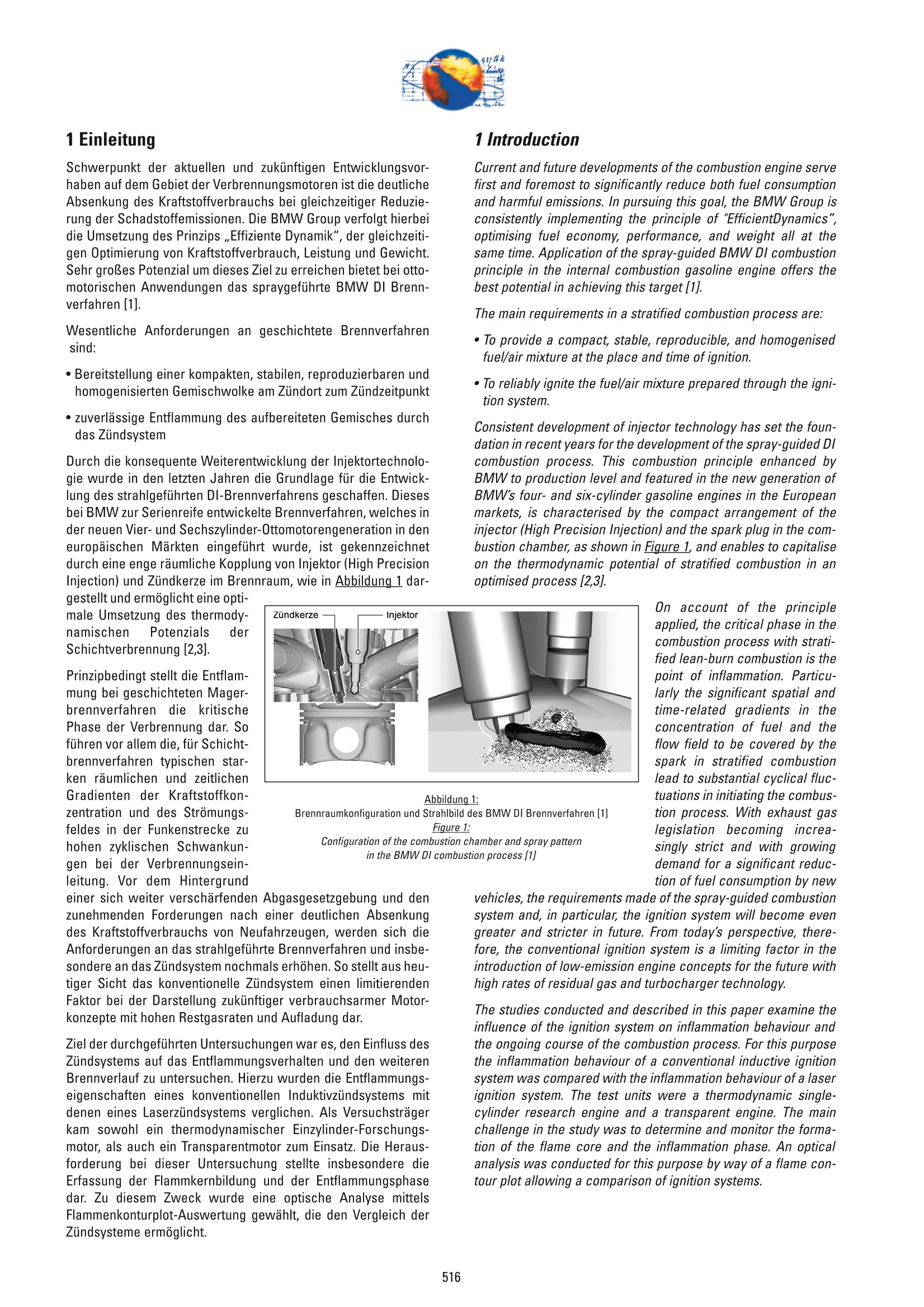
还剩14页未读,是否继续阅读?
继续免费阅读全文产品配置单


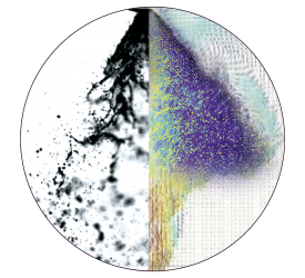

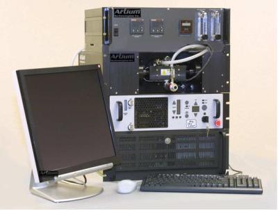
北京欧兰科技发展有限公司为您提供《喷射导引燃烧系统中热动力学潜能检测方案(流量计)》,该方案主要用于汽车电子电器中热性能检测,参考标准《暂无》,《喷射导引燃烧系统中热动力学潜能检测方案(流量计)》用到的仪器有PLIF平面激光诱导荧光火焰燃烧检测系统、德国LaVision PIV/PLIF粒子成像测速场仪、LaVision SprayMaster 喷雾成像测量系统、LaVision HighSpeedStar 高帧频相机、汽车发动机多参量测试系统。
我要纠错


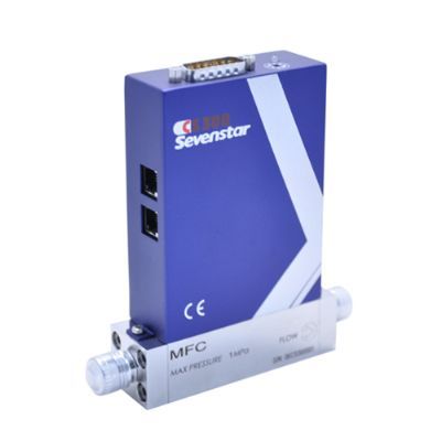


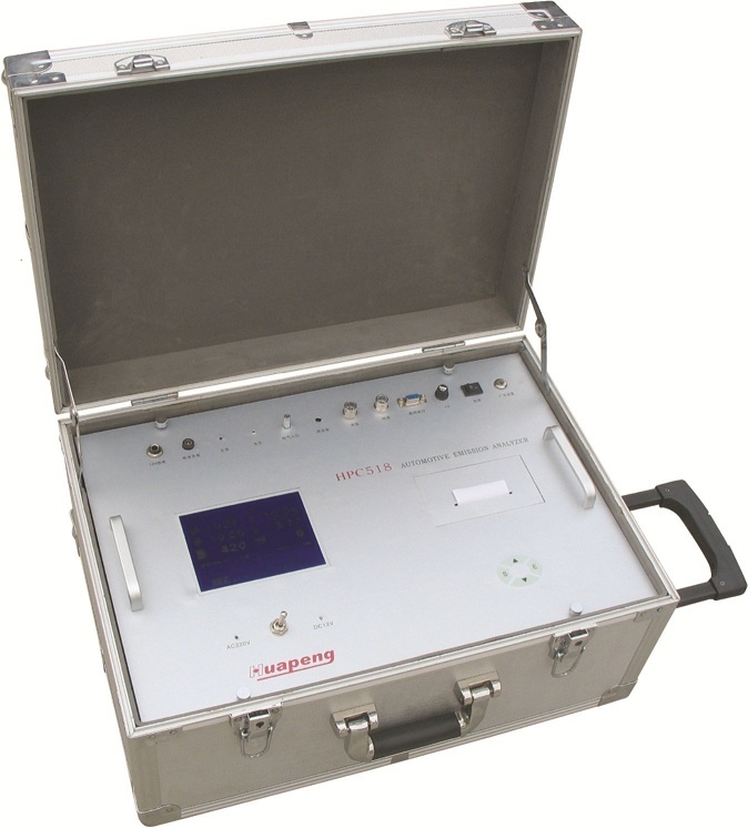
相关方案
 咨询
咨询