

方案详情文
智能文字提取功能测试中
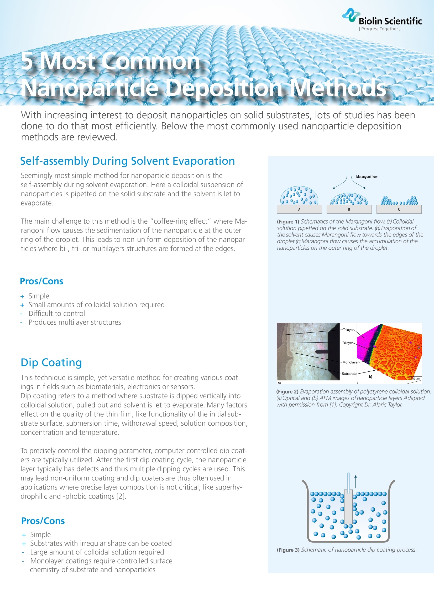
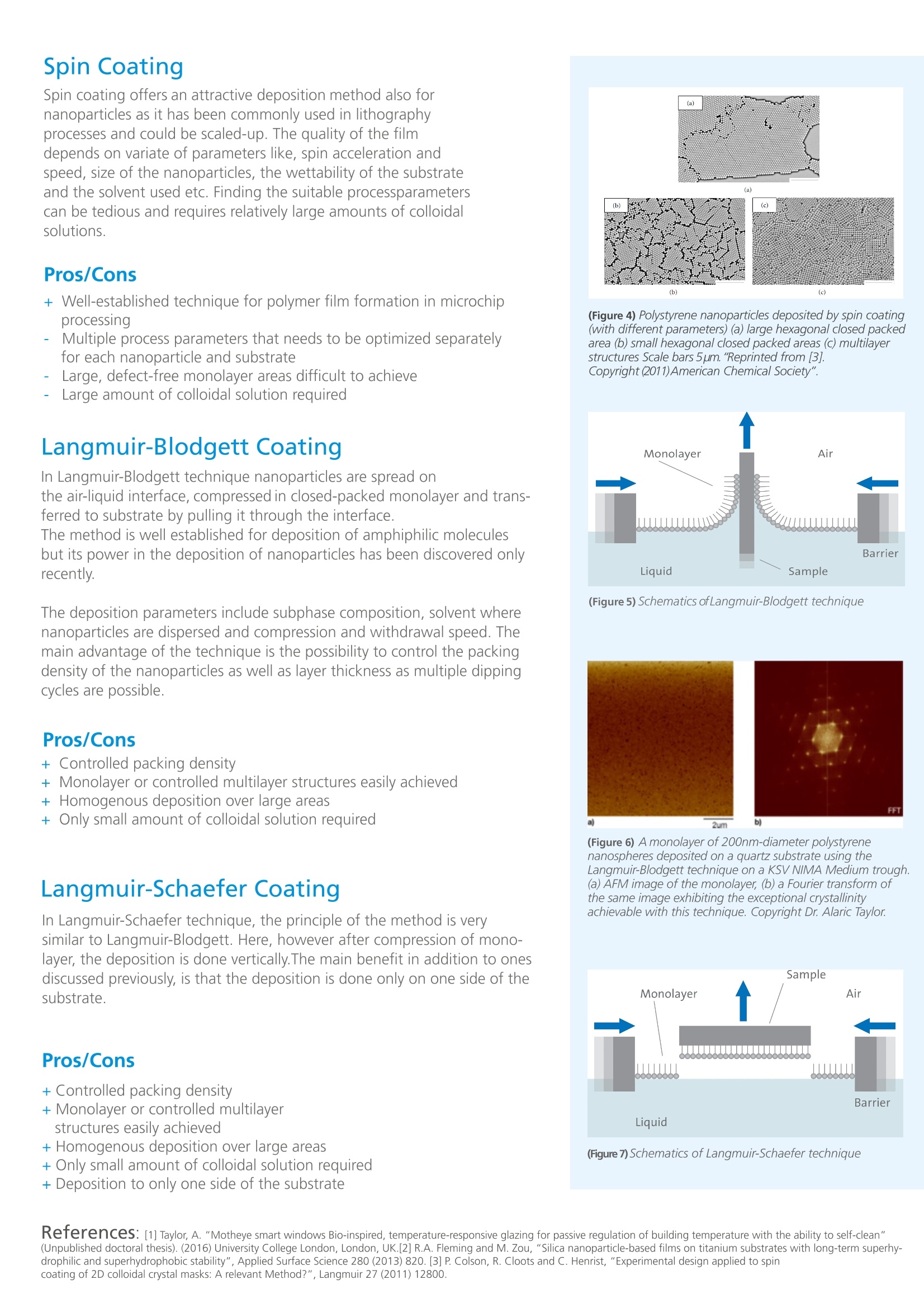
Biolin Scientific [ Progress Together]5 Most commonZNanoparticle Deposition Methods With increasing interest to deposit nanoparticles on solid substrates, lots of studies has beendone to do that most efficiently. Below the most commonly used nanoparticle depositionmethods are reviewed. Self-assembly During Solvent Evaporation Seemingly most simple method for nanoparticle deposition is theself-assembly during solvent evaporation. Here a colloidal suspension ofnanoparticles is pipetted on the solid substrate and the solvent is let toevaporate. The main challenge to this method is the "coffee-ring effect" where Ma-rangoni flow causes the sedimentation of the nanoparticle at the outerring of the droplet. This leads to non-uniform deposition of the nanopar-ticles where bi-, tri- or multilayers structures are formed at the edges. Pros/Cons 十Simple十- Small amounts of colloidal solution required Difficult to control Produces multilayer structures Dip Coating This technique is simple, yet versatile method for creating various coat- ings in fields such as biomaterials, electronics or sensors.Dip coating refers to a method where substrate is dipped vertically intocolloidal solution, pulled out and solvent is let to evaporate. Many factorseffect on the quality of the thin film, like functionality of the initial sub-strate surface, submersion time, withdrawal speed, solution composition,concentration and temperature. To precisely control the dipping parameter, computer controlled dip coat-ers are typically utilized. After the first dip coating cycle, the nanoparticlelayer typically has defects and thus multiple dipping cycles are used. Thismay lead non-uniform coating and dip coaters are thus often used inapplications where precise layer composition is not critical, like superhy-drophilic and-phobic coatings [2]. Simple Substrates with irregular shape can be coated Large amount of colloidal solution required Monolayer coatings require controlled surfacechemistry of substrate and nanoparticles (Figure 1) Schematics of the Marangoni flow. (a) Colloidalsolution pipetted on the solid substrate. (b)Evaporation ofthe solvent causes Marangoni flow towards the edges of thedroplet (C)Marangoni flow causes the accumulation of thenanoparticles on the outer ring of the droplet. (Figure 2) Evaporation assembly of polystyrene colloidal solution.(a)Optical and (b) AFM images ofnanoparticle layers Adaptedwith permission from [1]. Copyright Dr. Alaric Taylor. (Figure 3) Schematic of nanoparticle dip coating process. Spin Coating Spin coating offers an attractive deposition method also fornanoparticles as it has been commonly used in lithographyprocesses and could be scaled-up. The quality of the filmdepends on variate of parameters like, spin acceleration andspeed, size of the nanoparticles, the wettability of the substrateand the solvent used etc. Finding the suitable processparameterscan be tedious and requires relatively large amounts of colloidalsolutions. Pros/Cons 十Well-established technique for polymer film formation in microchipprocessing -Multiple process parameters that needs to be optimized separatelyfor each nanoparticle and substrate Large, defect-free monolayer areas difficult to achieve Large amount of colloidal solution required Langmuir-Blodgett Coating In Langmuir-Blodgett technique nanoparticles are spread on the air-liquid interface, compressed in closed-packed monolayer and trans-ferred to substrate by pulling it through the interface. The method is well established for deposition of amphiphilic moleculesbut its power in the deposition of nanoparticles has been discovered onlyrecently. The deposition parameters include subphase composition, solvent wherenanoparticles are dispersed and compression and withdrawal speed. Themain advantage of the technique is the possibility to control the packingdensity of the nanoparticles as well as layer thickness as multiple dippingcycles are possible. Pros/Cons + Controlled packing density 十Monolayer or controlled multilayer structures easily achieved十十 FHomogenous deposition over large areas Only small amount of colloidal solution required Langmuir-Schaefer Coating In Langmuir-Schaefer technique, the principle of the method is verysimilar to Langmuir-Blodgett. Here, however after compression of mono-layer, the deposition is done vertically.The main benefit in addition to onesdiscussed previously, is that the deposition is done only on one side of thesubstrate. + Controlled packing density+ Monolayer or controlled multilayerstructures easily achieved+Homogenous deposition over large areas+ Only small amount of colloidal solution required+Deposition to only one side of the substrate (c) (Figure 4) Polystyrene nanoparticles deposited by spin coating(with different parameters) (a) large hexagonal closed packedarea (b) small hexagonal closed packed areas (c) multilayerstructures Scale bars 5um. "Reprinted from [3]. Copyright(2011)American Chemical Society". (Figure 5) Schematics ofLangmuir-Blodgett technique (Figure 6) A monolayer of 200nm-diameter polystyrenenanospheres deposited on a quartz substrate using theLangmuir-Blodgett technique on a KSV NIMA Medium trough.(a) AFM image of the monolayer, (b) a Fourier transform ofthe same image exhibiting the exceptional crystallinityachievable with this technique. Copyright Dr. Alaric Taylor. (Figure 7) Schematics ofLangmuir-Schaefer technique ( Reter e nces: [1] Taylor, A. "M ot h e y e sma r t w indows B io- i nspired, temp e r at u r e -r esp ons iv e glaz i ng f o r p a s s i ve r e gula t i o n o f bui l di n g t empera t ure w i t h t he a b i l i t y t o self- cle a n" (U n pu b lish ed doct o r a l the s i s ) .(201 6 ) Un i v e rs i ty Coll e ge Lon do n , L o n d o n , UK . [ 2 ] R.A. F l e m i ng a nd M . Z o u , "S i li ca nanop a r t i cl e- b as e d film s o n t it a n i u m su bs trates w i th l o ng - te r m su p erh y-drop h ilic a nd s u p erh yd ro ph ob i c s t a bilit y", Ap p l ied S u r f ac e Science 2 8 0 ( 20 13 )820 . [ 3] P . C o ls o n , R. Cl o o t s an d C . H enri s t, "Expe r i m e n t a l de sign a p p l ie d t o sp in ) 纳米光刻是一种非常有前途的制造技术。不同于激光干涉,深紫外,电子束或离子束光刻,纳米光刻技术拥有平行放大的特点,以及在复杂基底结构如曲面上刻蚀的能力。这项技术的初始投资成本较低,且可以应用于多种材料。基底可以是非导电的、半刚性的、透明的或非透明的,而纳米粒子本身(通常是纳米球)可以由金属、无机物或聚合物组成。 探索纳米结构的技术可以分为研究长程有序(超过数万个重复单位)和短程有序(数百到数千个重复单位在多晶排列)两种。对于自组装过程,纳米粒子光刻技术可以通过基底特性的帮助,实现长程晶态有序自组装过程。然而,对于那些大多数只需要中程或短程有序的高填充比率--如制备小批量原理性实验制备--纳米微粒光刻技术就成为了首选技术。 纳米粒子光刻一般分为两个阶段:?胶体掩模的形成?在胶体掩膜的帮助下,完成沉积或蚀刻 在一个自组装过程中,胶体掩模制作的关键是了解制备过程中使用的纳米材料的具体性质。基于此,我们可以开始调控自组装的驱动力。例如粒子间在润湿线表现出的相互作用力,以及它在基底表面移动。 一旦在选择的基板上得到了单层纳米粒子掩膜,就可以通过第二步过程的应用转化成无数不同的纳米结构拓扑。这些包括但不限于:等离子体刻蚀、物理气相沉积和溶剂型剥离。这些标准技术的不同组合可以产生一系列的纳米结构。 了解纳米粒子间的相互作用特性 纳米颗粒可以由多种材料制成,如金属、金属氧化物和聚合物。纳米粒子的表面能很高,这是由于较高的比表面所致。裸露的纳米粒子倾向通过吸附周围分子、凝结、聚集等这样的方式降低比表面积来达到稳定状态。在光刻应用中,三维的聚集体的形成是不可取的。通过修饰粒子表层,控制纳米颗粒凝固的趋势。配体分子可以附着在纳米颗粒表面上,其存在可以阻止团聚,并在溶剂中控制粒子的溶解度。悬浮液中的纳米颗粒通常是一些组分复杂的物质,一个由软的有机外壳包裹的固态表面。 理解这一点可以在选择掩膜时更好地了解材料本质。 常见的胶体掩膜 聚苯乙烯和二氧化硅纳米颗粒是最常用的制备胶体掩模材料。可以通过合成或购买单分散胶体溶液来得到,粒径从5纳米到数10微米不等。由于后期制备纳米结构与纳米粒子的粒径分布有直接的关系,简单的调整纳米颗粒的大小即可改变纳米结构的特征。 考虑使用纳米微球光刻技术的人都会很快注意到制备胶体掩膜的一些问题。乍一看,似乎在固体基底上获得纳米颗粒只是将固体浸入到纳米粒子溶液中。对于某些应用来说,这种做法可能是正确的,但对于纳米微球的光刻技术来说,这几乎是不可能成功的。如果要想形成均匀的单层纳米颗粒,则需要一个可控性更好的制备技术。 要阅读更多关于胶体晶体掩膜的制备方法,请下载题为“最常见的5种纳米颗粒沉积方法”的短篇综述。
关闭-
1/2
-
2/2
产品配置单

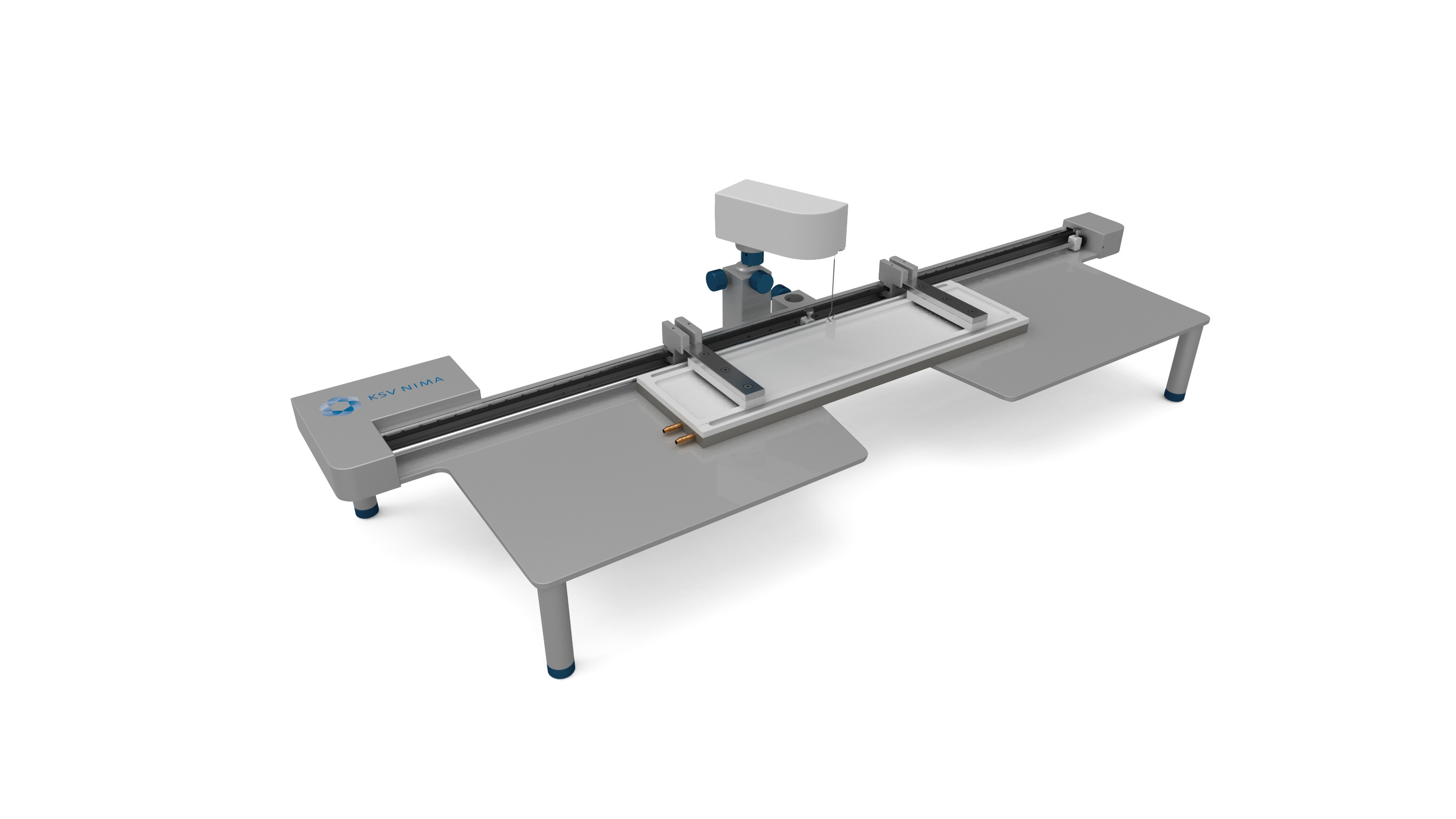
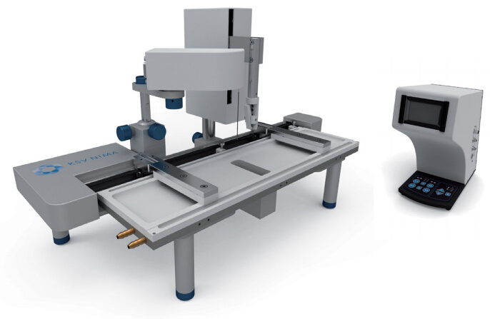
瑞典百欧林科技有限公司为您提供《纳米粒子中纳米粒子光刻检测方案(LB膜分析仪)》,该方案主要用于其他中纳米粒子光刻检测,参考标准《暂无》,《纳米粒子中纳米粒子光刻检测方案(LB膜分析仪)》用到的仪器有KSV NIMA常规 交替型LB膜分析仪。
我要纠错
相关方案
 咨询
咨询