方案详情文
智能文字提取功能测试中
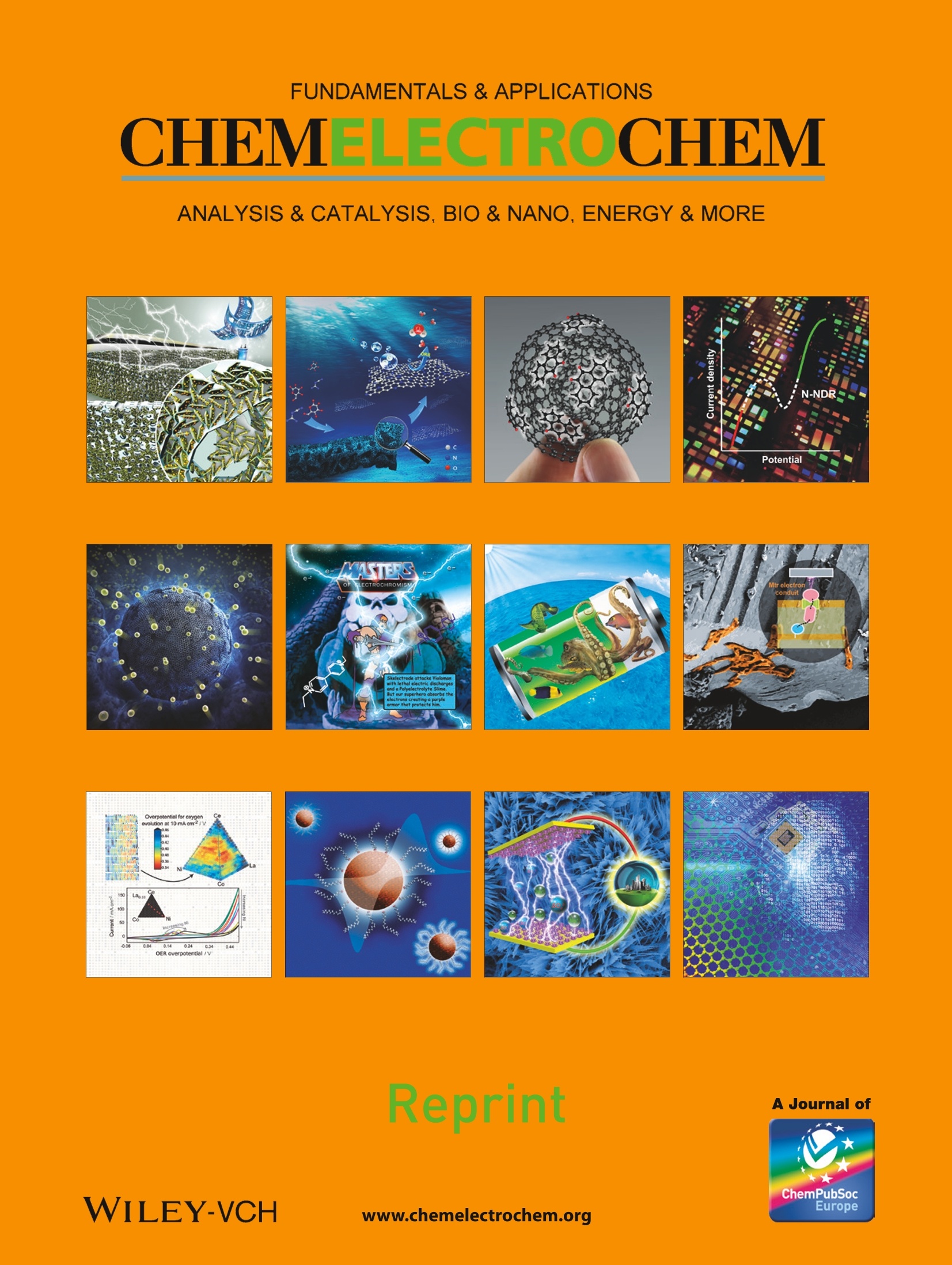
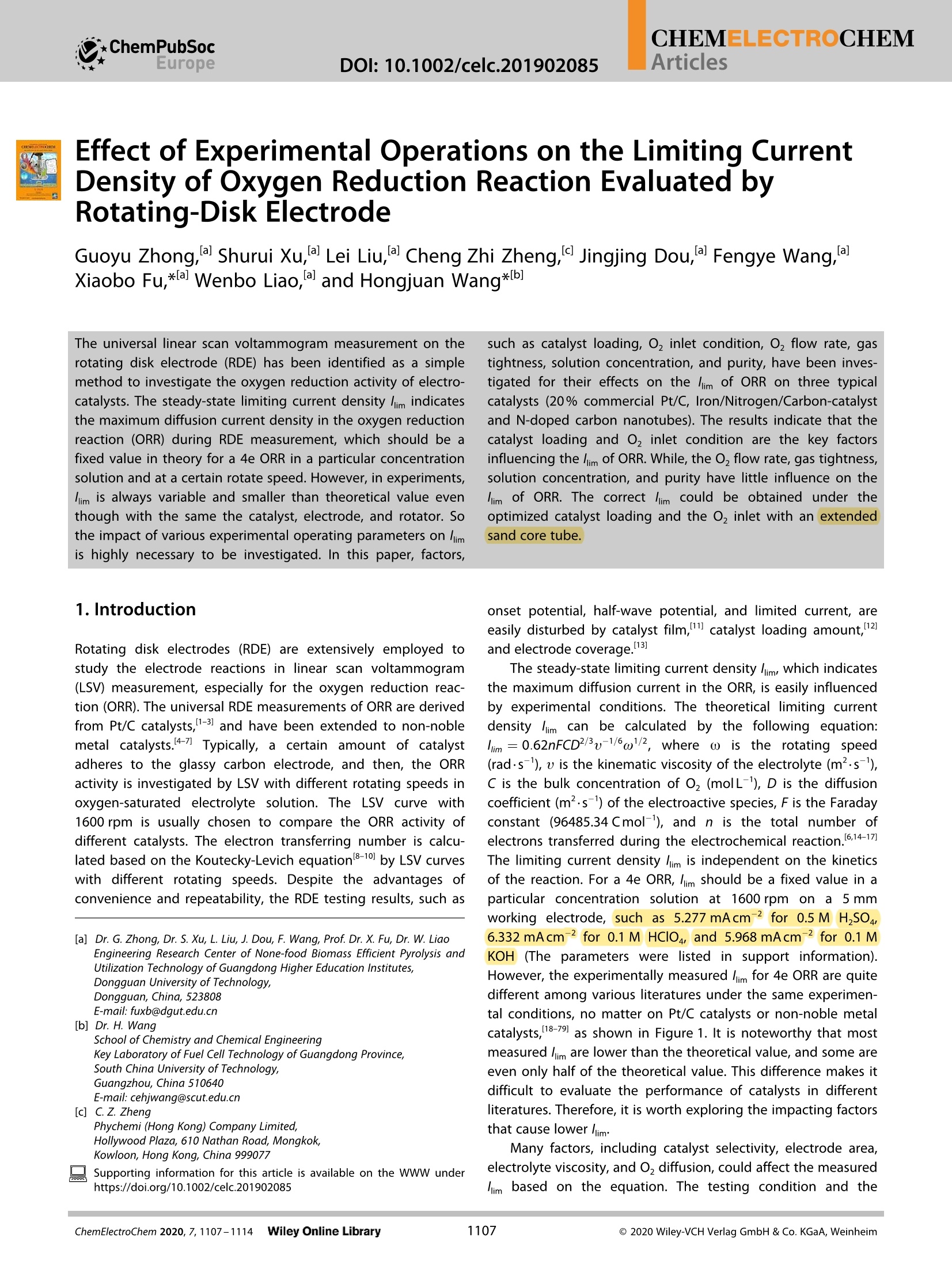
FUNDAMENTALS & APPLICATIONS CHEMELECTROCHEMArticlesDOI: 10.1002/celc.201902085 CHEMELECTROCHEM ANALYSIS & CATALYSIS. BIO & NANO, ENERGY & MORE Reprint A Journal of WILEY-VCH www.chemelectrochem.org Effect of Experimental Operations on the Limiting CurrentDensity of Oxygen Reduction Reaction Evaluated byRotating-Disk Electrode Guoyu Zhong,Ial Shurui Xu,Ial Lei Liu,al Cheng Zhi Zheng,a Jingjing Dou,al Fengye Wang,aXiaobo Fu,*lal Wenbo Liao, al and Hongjuan Wang*Ib The universal linear scan voltammogram measurement on therotating disk electrode (RDE) has been identified as a simplemethod to investigate the oxygen reduction activity of electro-catalysts. The steady-state limiting current density lim indicatesthe maximum diffusion current density in the oxygen reductionreaction (ORR) during RDE measurement, which should be afixed value in theory for a 4e ORR in a particular concentrationsolution and at a certain rotate speed. However, in experiments,lim is always variable and smaller than theoretical value eventhough with the same the catalyst, electrode, and rotator. Sothe impact of various experimental operating parameters on limis highly necessary to be investigated. In this paper, factors, 1. Introduction Rotating disk electrodes (RDE) are extensively employed tostudy the electrode reactions in linear scan voltammogram(LSV) measurement, especially for the oxygen reduction reac-tion (ORR). The universal RDE measurements of ORR are derivedfrom Pt/C catalysts,I1-3] and have been extended to non-noblemetal catalysts.[4-7] Typically, a certainn amount of catalystadheres to the glassy carbon electrode, and then, the ORRactivity is investigated by LSV with different rotating speeds inoxygen-saturated electrolyte solution. The LSV curve with1600 rpm is usually chosen to compare the ORR activity ofdifferent catalysts. The electron transferring number is calcu-lated based on the Koutecky-Levich equation18-10l by LSV curveswith different rotating speeds. Despite the advantages ofconvenience and repeatability, the RDE testing results, such as [a] Dr. G. Zhong, Dr. S. Xu, L.Liu, J. Dou, F. Wang, Prof. Dr. X. Fu, Dr. W. Liao such as catalyst loading, O, inlet condition, O, flow rate, gastightness, solution concentration, and purity, have been inves-tigated for their effects on the lim of ORR on three typicalcatalysts (20% commercial Pt/C, Iron/Nitrogen/Carbon-catalystand N-doped carbon nanotubes). The results indicate that thecatalyst loading and O2 inlet condition are the key factorsinfluencing the lim of ORR. While,the O, flow rate, gas tightness,solution concentration, and purity have little influence on thelim of ORR. The correct im could be obtained under theoptimized catalyst loading and the O inlet with anextendedsand core tube. onset potential, half-wave potential, and limited current, areeasily disturbed by catalyst film,"" catalyst loading amount,2and electrode coverage.13 The steady-state limiting current density lim, which indicatesthe maximum diffusion current in the ORR, is easily influencedby experimental conditions. The theoretical limiting currentdensity im can be calculated by the following equation:1im=0.62nFCD2/3u-1/6ω1/2, where o is the rotating speed(rad·s-), u is the kinematic viscosity of the electrolyte (m².s),C is the bulk concentration of O (molL-), D is the diffusioncoefficient (m²-s-) of the electroactive species, F is the Faradayconstant (96485.34 Cmol), and n is the total number ofelectrons transferred during the electrochemical reaction.6,14-17]The limiting current density lim is independent on the kineticsof the reaction. For a 4e ORR, im should be a fixed value in aparticular concentration solution at 1600 rpm on a 5 mmworking electrode, such as 5.277 mAcm for 0.5 M HSO,6.332 mAcm-² for 0.1 M HClO,and 5.968 mAcm-²for 0.1 MKOH (The parameters were listed in support information).However, the experimentally measured lim for 4e ORR are quitedifferent among various literatures under the same experimen-tal conditions, no matter on Pt/C catalysts or non-noble metalcatalysts,[18-79] as shown in Figure 1. It is noteworthy that mostmeasured / im are lower than the theoretical value, and some areeven only half of the theoretical value. This difference makes itdifficult to evaluate the performance of catalysts in differentliteratures.Therefore, it is worth exploring the impacting factorsthat cause lower lim. Engineering Research Center of None-food Biomass Efficient Pyrolysis andUtilization Technology of Guangdong Higher Education Institutes,Dongguan University of Technology,Dongguan, China, 523808E-mail: fuxb@dgut.edu.cn[b] Dr. H.WangSchool of Chemistry and Chemical EngineeringKey Laboratory of Fuel Cell Technology of Guangdong Province,South China University of Technology,Guangzhou, China 510640E-mail: cehjwang@scut.edu.cn[c] C. Z. ZhengPhychemi(Hong Kong) Company Limited,Hollywood Plaza, 610 Nathan Road, Mongkok,Kowloon, Hong Kong, China 999077Supporting information for this article is available on the WWW underhttps://doi.org/10.1002/celc.201902085 Many factors, including catalyst selectivity, electrode area,electrolyte viscosity, and O diffusion, could affect the measuredlim based on the equation. The testing condition and the measured lim of typical 4e ORR on different ORR catalysts fromdifferent literature were shown in Figure 1 and summarized inTable S1. It can be seen that Pt/C catalysts, no matter fromcommercial or homemade, show much different measured lim.Most of which are smaller than the theoretical value, no matterthe loading value. Moreover, non-noble metal catalysts show asimilar rule. All the measurements were conducted on the PINEdisk electrode with the electrode area of ~0.2 cmand with thesame preparation method of the thin-film electrode by castingcatalyst-containing inks onto the glassy carbon electrodes. Soeven though the same electrode area, the same electrodefabrication method and the high enough catalyst loading wereconducted, the measured im are still quite different, and mostare less than the theoretical value. Based on this, it is reasonable to infer that there must besome other experimental operations affecting ORR, leading tothe different measured /im. So, in order to obtain correct resultsand to compare with other literature, it is highly imperative tofind the potential vital factors influencing ORR or the measuredlim. In this work, three factors, catalyst loading that affecting theselectivity of ORR, O inlet condition affecting O2diffusion, andsolutionconcentration anddpurity affecting the electrolyteviscosityi were chosenntoinvestigatettlheir effect onitthemeasured lim for ORR with 20% commercial Pt/C, Iron/Nitrogen/Carbon-catalyst (Fe-N-C) and N-doped carbon nanotubes(NCNTs) as three typical model catalysts. 2. Results and Discussion 2.1. Influence of the Catalyst Loading The effect of catalyst loading on the measured lim was firstlyinvestigated. As shown in Figure 2, different loading Pt/C,NCNTs, and Fe-N-C catalysts were evaluated by RDE in 0.5 MH,SO4 with 40 mL min-O bubbled with a sand core exhaustpipe. For Pt/C (Figure 2a), the measured /im reach the theoreticallimiting in 0.5 M HzSO4 solutions when the catalyst loading ishigherr tthan203.82 ugcm-. Theieexcessiveloadingof815.28 ug cm-results in the lower lim and fluctuant LSV curve,which is due to the limitation of excessive electron and masstransfer.80] For NCNTs and Fe-N-C, the measured im increasewith the increase of catalyst loading and then reach thetheoretical value. When the loading is low, it is insufficient forthe catalyst to completely reduce its surface O to H0 due tothe lack of active sites. When the loading is enough, the imreaches the theoretical value because of the complete reduc-tion of the surface O, on the catalyst. A further increase inloading does not improve the im for the limited dissolvedoxygen concentration. The results indicate that the lim measured could achieve the theoretical value with an appropriateloading for different catalysts. The appropriate catalyst loadingis related to its catalytic performance. The higher the perform-ance of the catalysts, the lower the loading demands. For thesake of analysis, all the subsequent experiments were per-formed using these catalysts with the appropriate loading. E/V vs Ag/AgCI Figure 2. LSV curves of Pt/C, NCNTs, and Fe-N-C with different loadings forORR in 0.5 M H,SO saturated with O2 at 1600 rpm and the scan rate of10mVs. 2.2. Influence of the Electrolyte Solution Linear scan voltammograms for ORR are usually measured withRDE in 0.1 M KOH, 0.1 M HCIO4, or 0.5 M H,SO4 solution. Theconcentration and purity of the solution might affect theelectrolyte viscosity or O2 diffusion coefficient, resulting in thedifference lim. Therefore, experiments were designed to explore the effect of solution concentration and purity on the lim of ORRinLLSVmeasurement.So,iPPt/C ((203.82 ugcm-),),NCNTs(1019.10 ugcm-), and Fe-N-C (815.28 ug cm=) were evaluatedby LSV with RDE in different solutions under 40 mLmin-10using a PINE electrolytic cell with a sand core exhaust pipe. Asshown in Figure 3a-c, the im of different catalysts increaseslightly as the concentration of the HSO4 solution increasingfrom 0.25 M to 0.5 M. When the concentration increases to1.0 M, the im of different catalysts decrease sharply. For theKOH solution, the l im of ORR on different catalysts keep almostunchanged, with the concentration increasing from 0.05 M to0.2 M, as shown in Figure 3d-f. Moreover, 85% purity KOH hasno significant impact on the lim of ORR on different catalysts.According to the related studies,81-83 the concentration orpurity changes in this work are not enough to observably affectthe electrolyte viscosity, O2 solubility or O2 diffusion rate. Fromthese results, it can be concluded that solution purity andconcentration within a certain range have little influence on theim of ORR. 2.3. Influence of O, Condition O2 diffusion in solution is a critical factor and directly impactsthe lim of ORR in LSV measurement. Except for the influence ofelectrolyte, O2 diffusion in solution is also depended on O, inle1conditions, O, flow, and gas tightness. O, inlet conditions donot have uniform experimental standards. 5 mm sand core tubeis an O inflow accessory of the original electrolytic cell (PINE).While, in many labs, simple glass tube or Teflon tube withoutsand core are directly used in their homemade electrolytic cell.To investigate the influence of O, inlet condition, the RDE testsof different catalysts were respectively conducted with 3Teflon gas tube, 3 mm and 5 mm sand core tubes (3 mm and5 mm represent the diameter of the sand core), as shown inFigure 4 and S1. Surprisingly, the O inlet condition significantlyimpacts the /im of ORR on the three catalysts at the same 0flow of 40 mL min-1. In the experiments with 3 inlet gas tube,all three catalysts exhibit about 1 mAcm’lower im comparedwith those of using a 5 mm sand core tube in 0.5 M H,SO4,which indicates the O inlet conditions have a significantinfluence on the resulting. This difference in lim is associatedwith the O dissolution and diffusion in solution. As shown irFigure 4a, compared with 3 bubbles discharged by 3 gastube, about 30 bubbles are discharged by the 5 mm sand coretube. The diffusion coefficient of oxygen is a constant under thecertain experimental conditions. When the O, flow is the same,the more bubbles, the more 02 contact area is, which providesabundant Odissolution and diffusion. As is well-known, theoxygen on the electrode surface is quickly consumed duringRDE tests, especially at high speeds. In order to maintain theoxygen concentration for ORR, oxygen needs to spread quicklyto the electrode surface. Therefore, a 5 mm sand core tubeproviding abundant O, dissolution and diffusion, is necessary toobtain higher limiting current value. Supplementary experiments were carried out to explore theinfluence of O flow and gas tightness on the im. In this ENvs Ag/AgCI E/V vs Ag/AgCI Figure 3. ORR polarization curves of (a, d) Pt/C, (b,e) NCNTs, and (c, f) Fe-N-C in (a, b, c) HSO and (d, e, f) KOH with different concentrations at 1600 rpmand the scan rate of 10 mVS. experiment, RDE tests were evaluated in a PINE electrolytic cellwith a 5 mm sand core exhaust pipe. As shown in Figure 5a-c,the LSV curves of ORR under different O, flows were almostoverlapping for the three catalysts. The im slightly decreasewith the decrease of O, flow. This indicates that a small O, flowcan keep an Oz-saturation for ORR, when the O dissolution anddiffusion is enough in solution by the 5 mm sand core tube. Toinvestigate the influence of gas tightness on the lim, a semi-hermetic construction was provided by PINE electrolytic cell wrapped well in plastic film. As a contrast, LSV tests were alsocarried out in the open electrolytic cell, as shown in Figure 5d-f.The performance of ORR in open electrolytic cell is a little worsethan that in the semi-hermetic electrolytic cell due to the lowerpartial pressure of oxygen. So gas tightness has some influenceon the lim of ORR, but its influence is much weaker than that ofthe inlet condition. In order to verify the pivotal role of O inflow tube, LSV testswith various rotating speeds and Oflow rates using 3 gas Figure 4. (a) The O, inlet conditions of 3 gas tube and 5 mm sand core tube. ORR polarization curves of (b) Pt/C, (c) NCNTs, and (d) Fe-N-C in 0.5 MH,SOwith different intake-tube, at 1600 rpm and the scan rate of 10 mVs. tube were conducted, respectively. As shown in Figure 6a and6d, at low speeds (200-900 rpm), the /im of 3 gas tube arealmost the same as that of the 5 mm sand core tube, which isapproximate to the theoretical value. However, at high speeds(≥1200rpm), the /im of ORR using a D3 gas tube is muchsmaller than that of using a 5 mm sand core tube. Moreover, for3 gas tube, the LSV curves at higher speeds (≥2000rpm)overlap with the LSV curve at 1600 rpm. The LSV curve at2500 rpm even drops to the same level of 900 rpm. Thisphenomenon is called as the curves crossover, which is acommon error during testing. It can be explained as follows:the electrode surface quickly consume much more oxygen athigher speeds than that at lower speeds; the poor O2diffusionby 3 gas tube makes ORR hard to further proceed at highspeeds, leading to smaller limiting current. The poor O2dissolution and diffusion by D3 gas tube cannot be improvedby merely increasing O2flow, as shown in Figure S2. Accord-ingly, the lim do not increase along with the O, flow increasing.So, it can be concluded that the O2 inflow tube plays a crucialrole in O, dissolution and diffusion, which should be regardedas the critical factor of improving the lim of ORR in LSVmeasurement. 3. Conclusions The limiting current density of Pt/C, Fe-N-C, and NCNTs weremeasured for ORR under different experimental operatingconditions, including catalyst loading, O2 inlet condition, O2flow rate, gas tightness, solution concentration and purity.Critical factors for obtaining correct lim are catalyst loading andO2 inlet condition. The correct /lim could be obtained under theproper catalyst loading that is dependent on the catalyticperformance and using extended sand core tube as O, inlettube to ensure the effective O dissolution and diffusion. While,the O flow, gas tightness, solution concentration, and purityalso have a weak influence on the ORR /im. These differences inexperimental operation probably cause the different measuredim in the literatures. This study provides some useful instruc-tions in experimental RDE measurement for ORR and mayextend to other electrochemical experiment measurements. Experimental Section Materials preparation 20% commercial Pt/C was bought from Johnson Matthey Com-pany. Fe-N-C catalyst was synthesized by pyrolyzing ferrous (a) J (b) 0 -1 -1 NCNTs Fe-N-C -5- -5 ·open electrolytic cell open electrolytic cell ·semi-hermetic electrolytic cell -semi-hermetic electrolytic cell -6- -6- -0.2 0.0 0.2 0.4 0.6 0.8 -0.2 0.0 0.2 0.4 0.6 0.8 E/ vs Ag/AgCI E/V vs Ag/AgCI Figure 5. ORR polarization curves of (a, d) Pt/C, (b, e) NCNTs, and (c, f) Fe-N-C in 0.5 M H,SO with different (a,b, c) O, flow and (d, e, f) gas tightness, at1600 rpm and the scan rate of 10 mVs. acetate, 1,10-phenanthroline, and ZIF-8 based on the optimizedconditions.84N-doped CNTs (NCNTs) were made according to theliterature.[85] Electrochemical measurement LSV measurements were conducted using an AutoLab PGSTAT204potentiostat/galvanostat, a Pine Instruments rotator, and a glassycarbon rotating disk electrode (5 mm, Pine Instrument Co.). Agraphite rod and an Ag/AgCl electrode saturated with KCl wereused as the auxiliary electrode and the reference electrode,respectively. According to our previous method,4 catalyst suspen- sion was prepared, and 20 uL suspension was pipetted onto theglassy carbon disk electrode to obtain a working electrode withcatalyst loading of 101.91~815.28 ugcm-. H,SO and KOH aque-ous solutions with different concentrations were used as theelectrolyte (See the details in results and discussion). LSV measure-ments were carried out with a scan rate of 10 mVs-1 at thepotential range of -0.2~0.80Vand -1.0~0.2V versus Ag/AgCl inoxygen-saturated (40 mL min-oxygen flow and 5mm sand coretube as intake-tube without special instruction) acid and alkalinesolution, respectively. Figure 6. ORR polarization curves of (a) Pt/C, (b) NCNTs,and (c) Fe-N-C with 3 gas tube and (d) Pt/C with 5 mm sand core tube, in 0.5 M HSO at differentrpm and the scan rate of 10 mVs. Acknowledgements This work was supported by Engineering Research Center of None-food Biomass Efficient Pyrolysis and Utilization Technology ofGuangdong Higher Education Institutes (2016GCZX009), NationalNatural Science Foundation of China (No.21905044), NaturalScience Foundation offGuangdong Province (No.2018A030310004), Foundation of Doctor's Workstation of MCNAIRNEW POWER CO.,LTD at the Dongguan University of Technology(GC200104-40, No. 186100030017), High-level Talents Project ofDongguan University of Technology (KCYKYQD2017017), andDongguan Social Science and Technology Development ProjectDeclaration (No. 2019507140431). We greatly appreciate serviceengineer Chengzhi Zheng at Phychemi (Hong Kong) CompanyLimited for his constructive suggestions on RDE measurements. Conflict of Interest The authors declare no conflict of interest Keywords: oxygen reduction reaction· rotating disk electrode·limiting current· experimental operations ( [1 ] F. Gloaguen, F. Andolfatto, R. Durand, P. O zil, J.Ap p l. Electrochem. 1994, 24, 863-869. ) [2] T. J. Schmidt, H. A. Gasteiger, G. D. Stab, P. M. Urban, D. M. Kolb, R. J.. Behm, J. Electrochem. Soc. 1998, 145,2354-2358. [3] S. S. Kocha, K. Shinozaki, J. W. Zack, D. J. Myers, N. N. Kariuki, T. Nowicki,V. Stamenkovic, Y. Kang, D. Li, D. Papageorgopoulos, Electrocatalysis2017, 8,366-374. [4] G. Zhong, S. Li, S. Xu, W. Liao,X. Fu, F. Peng,ACS Sustainable Chem. Eng.2018,6,15108-15118. [5] Z. Guoyu, W. Hongjuan, Y. Hao, P. Feng, Acta Chim. Sin. 2017, 75, 943-966. [6] M. W. Li, M. H. Fu, Y. Cao, H. Wang, H. Yu, Z. Qiao, H. Liang, F. Peng,ChemElectroChem 2019,6,359-368. [7] B. H. Hou, Q.Wang, W. C. Lu, Y. Xiao, H. X. Zhang, M. J. Liao, Z. C. Zhu, P.Chen, ChemElectroChem 2018,5,1854-1861. [8] Y. Garsany, J. Ge, J. St-Pierre, R. Rocheleau, K. Swider-Lyons, ECS Trans.2013,58,3-14. [9] K. L. Hsueh, D. T. Chin, S. Srinivasan, J. Electroanal. Chem. InterfacialElectrochem. 1983, 153, 79-95. [10] H. Tang, J.Luo, J. Yu, W. Zhao, H. Song,S. Liao, ChemElectroChem 2018,5, 2041-2049. [11] Y. Garsany, O. A. Baturina, K.E. Swider-Lyons, S. S. Kocha, Anal. Chem.2010,82,6321-6328. [12] S. Taylor, E. Fabbri, P. Levecque, T.J. Schmidt, O. Conrad, Electrocatalysis2016,7,287-296. [13] J. Masa, C. Batchelor-McAuley, W. Schuhmann, R. G. Compton, Nano Res.2014,7,71-78. [14] H. Zhu, M. Chen, K. Li, X. Huang, F. Wang, ChemElectroChem 2018, 5,2126-2134. [15] T. L. Zhai, C. Xuan, J. Xu, L. Ban, Z. Cheng, S. Wang, D. Wang, B. Tan, C.Zhang, Chem. Asian J. 2018, 13, 2671-2676. ( [ 16] Y . S un, S. L i, Z. P . Jovanov, D. Bernsmeier, H. Wang, B. Paul, X. Wang, S. Kuhl, P. Strasser, ChemSusChem 2018, 11, 3388-3395. ) ( [17] R. Li , H. L i , J. Lon g , J. He, J. Zhang, H. Zhen g , X . Gou, ChemCatChem 2018, 1 0,4038-4046. ) ( [18] D . Geng, Y. Ch e n, Y. C he n , Y. L i , R . Li, X. Sun, S. Ye, S. K nights, Ener g y Environ. S ci. 2011, 4, 760-764. ) ( [19] S . Wang, L. Zhang, Z. Xia, A. Roy, D. W. Chang, J. B. B ae k , L. D ai, Angew. C hem. Int. Ed.Engl. 2012, 51 , 4209-4212. ) ( [20] L . Zou, J. Fan, Y. Zhou, C. Wang,J. Li, Z. Z o u, H. Yang, Nano Res. 2015, 8, 2777-2788. ) ( [21]Y. Liang, Y. Li, H. Wang, J. Zhou, J. Wang, T. Regier, H. Dai, Nat. Mater.2011,10,780-786. ) ( [22] Y. Li, W. Zhou, H . W ang, L. Xie, Y . L i ang, F. W e i, J.-C. I d robo, S . J. P ennycook, H. D a i, Nat. N anotechnol. 2012, 7 , 394. ) ( [23] R. Kou, Y . S hao, D. Wang, M. H. En g elhard, J. H . Kw a k, J. W ang, V. V . Viswanathan, C. Wang, Y. L in , Y. Wang, I. A. A ks a y, J. Liu , Electrochem. Commun. 2009, 1 1 , 954-957. ) ( [24] Z. Miao, X. Wang, M.-C. Tsai, Q. Jin, J. L iang, F. Ma, T. Wang, S. Z h eng, B.- J. Hwang, Y . Huang, S. G uo, Q . L i, Adv. Energy Mater.2018,8, 1801226. ) ( [25] R . Liu, D. Wu, X. Feng, K . Mullen, Angew. Chem. Int. Ed. 2010, 49, 25 6 5- 2569; Angew. Chem. 2 010, 1 22,2619-2623. ) ( [26] U . A. P aulus, T .J. S chmidt, H . A . G a steiger, R. J . B ehm, J. Electroanal. Chem. 2001,495, 134-145. ) ( [27] . $ S . M. Alia , K. O. Jensen, B. S. Pivovar , Y. Yan, ACS Catal. 2012, 2 , 858-863. [28] Y. Tan, C. Xu, G. C hen, N. Zheng, Q. Xie, E n ergy Environ. Sci. 2012, 5, 6923-6927. ) ( [29] Z. Wang, H. Jin, T. Meng, K. Liao, W. M eng, J . Y a ng, D . H e , Y . X i ong, S . M u, Adv. F unct. Mater. 2018, 28,1802596. ) ( [ 30] S. Yang, X. Feng, X. Wang, K. Mullen, Angew. C hem. Int. Ed. 2 011, 5 0, 5339-5343;Angew. Chem.2011,123,5451-5455. ) ( [31] M . Shao, A. Peles, K . Shoemaker, Nano Lett. 2011, 1 1,3714-3719. ) ( [ 32] H . W. L iang, W. Wei, Z. S.Wu, X. Feng, K . Mullen,J. Am. C hem. Soc. 2013, 135,16002-16005. ) ( [33] M . L onghi, S. Marzorati, S . C hecchia, B. S acchi, N . S anto, C . Zaffino, M. S cavini, Electrochim. Acta 2016, 2 22, 781-792. ) ( [34] H.W. L iang, X . Z huang, S. Bruller, X. Feng, K. Mullen, Nat. Commun. 2014,5,4973. ) ( [35] W. Li, D. Yang, H . C hen, Y . Gao, H. L i , E lectrochim. Acta 2015, 165, 191- 197. ) ( [36] A. H. A . Monteverde Videla, R. A. Moghadam Esf a hani, I. Pe te r, S. S pecchia, Electrochim. Acta 2015, 177, 51-56. ) ( [37] S. You, P . L uo, L . F ang, J. G ao, L . Liu, H . Xu, H . Z h ang, Y. Wa n g, Electrochim.Acta 2019,294,406-412. ) ( [38] R . Gokhale, Y. Chen, A. Serov, K. A rtyushkova, P.Atanassov, Electrochem. Commun. 2016, 7 2 , 140-143. ) ( [ 39] G . Daniel, E . Foltran, R. B randiele, L. Nodari, R. Pilot, E . Menna, G . A. Rizzi,A. A. Isse, C. Durante, A . Gennaro,J. Power Source s 2018 , 402,434-446. ) ( [40] C. Li, F. Sun,Y. Lin, J. Power Sources 2018,384, 48-57. ) ( [41] B . Y. Guan, L. Yu, X. W . Lou , Energy Environ. Sci.2016, 9,3092-3096. ) ( [42] Y . C hen, S . J i , Y . Wang, J. D o ng, W. Che n , Z. Li, R . S he n , L. Zheng, Z. Zhuang, D . W ang, Y . L i , Angew. C hem. I n t. Ed. 2017, 56, 6937-6941; Angew. Chem. 2017, 129,7041-7045. ) ( [ 43] C . H e, T. Zhang, F. S u n, C. Li , Y . L i n,Electrochim. Acta 2017, 231, 549- 556. ) ( [44] S . Dresp, F . L uo, R . Schmack, S. Ku h l, M. G li e ch, P. St rasser, Ene r gy Environ. Sci.2016,9,2020-2024. ) ( [45] X . Zhang, R. Liu, Y . Zang, G . Liu, G. Wang, Y . Zhang, H. Zhang, H. Zhao, Chem. Commun. 2016, 52,5946-5949. ) ( [ 46] J. Yang, H . S un, H. L iang, H. Ji, L. Song, C. Gao, H. Xu, Adv. Mater. 2016, 28,4606-4613. ) ( [47] B . You, F . Kang, P. Yin, Q. Zhang, Carbon 2016, 1 0 3, 9 - 15. ) ( [48] X . Huang, Z. Yang, B. Dong, Y. Wang, T. Ta n g, Y. Hou, Nanoscale 201 7 ,9, 8102-8106. ) ( [49] T . Zhan, X . Liu, S. Lu , W. Hou, Appl. Catal. B 2017,205,551-558. ) ( [50] W . Si, Z. Yang, X. W ang, Q. Lv , F. Zhao, X. Li , J. He, Y . Long, J. G a o, C. H uang, ChemSusChem 2 019,12, 1 73-178. ) ( [51] X. Bao, Y. Gong, J. Deng, S. Wang, Y. Wang, Nano Res. 2 017, 1 0, 1 258- 1267. ) ( [52] C. H. Choi, M. W. Chung, H. C. Kwon, S. H . P ark, S. I. Woo, J. Mater. Chem. A 2013,1,3694. ) ( [53] A. Kongkanand, S. K uwabata, G. Girishkumar, P. K amat, Langmuir 2006, 22,2392-2396. ) ( [ 54] Q . Shi, F. Peng, S . Liao, H. Wang, H. Yu , Z. Li u , B. Zhang, D. S u, J. Mater. Chem. A 2013, 1, 14853. ) ( [ 55] Z.K. Yang, L. Lin, A.-W.Xu, Smal 2016, 1 2 ,5710-5719. ) ( [56] S .Yu, X. C hi, J . Fan, X. Liang, W. Yang, Z . Wang, K . Han, H . Z h u, Int. J. Hydrogen Energy 2017,42,14501-14510 . ) [57] B. Merzougui, S. Bukola, R. Zaffou, Mater. Today: Proc. 2016, 3,691-695. ( [58] J. Wang, L. L i, X. Chen, Y . L u, W . Yang, X . Duan, Na n o Res. 201 7 , 10, 2508-2518. ) ( [59] S . S. A. Shah, T. Najam, C. C heng, L. Peng, R. Xiang, L. Zhang, J. Deng, W. Ding,Z. W ei, C hem. Eur.J. 2018, 24, 10630-10635. ) ( [ 60] A. Kong, X . Zhu, Z. Han, Y. Yu, Y. Zhang, B. Dong, Y . Shan, ACS Catal. 2014,4, 1 793-1800. ) ( [61] W. Niu, L. L i, X. Liu, N. Wang, J. Liu, W. Zhou, Z . Tang, S. C h en, J. A m . Chem. Soc. 2015, 137,5555-5562. ) ( [62] Q . Cheng, L. Yang, L . Z ou, Z . Zou, C . Chen, Z. H u , H. Yang, ACS Catal. 2017,7,6864-6871. ) ( [63] S . Fu, C. Zhu, J. Song, S. Feng, D . D u, M. H. Engelhard, D. Xiao, D. Li, Y. Lin, ACS Appl. Mater. Interfaces 2017, 9 , 36755-36761. ) ( [ 64] H . Jiang, Y. Liu, J. Hao, Y. W ang, W. Li, J. L i , ACS Sustainable Ch e m. Eng. 2 017,5,5341-5350. ) ( [ 65] M . Liu, J. Liu, Z . L i , Y. Son g , F. Wang,J . Catal. 2019, 370,21-29. ) ( [66] B . Liu, B. Huang, C . Lin, J. Ye, L . Ouyang, Appl. Surf. Sci.2017,411,487- 493. ) ( [67] Y. Chen, R. Gokhale, A. Serov, K. A rtyushkova,P. Atanassov, Nano Energy 2017,38, 2 01-209. ) ( [68] H. Shen, E . Gracia-Espino, J. Ma, K. Zang, J. Luo, L. Wang, S. Gao, X . Mamat, G. H u , T . Wagberg, S. G u o, Angew. Chem. Int . Ed . 20 1 7, 56 , 1 3800-13804; Angew. C h em. 2017, 129, 1 3 988-13992. ) ( [ 69] S . Y asuda, A . F u ruya, Y. Uchibori, J. Kim, K. Murakoshi, Adv . Funct. Mater. 2016,26,738-744. ) ( [70] G . A. Ferrero, K. Preuss, A. M a rinovic, A. B. Jorge, N. Mansor, D. J. Brett, A. B. Fuertes, M. Sevilla, M. M. Titirici, ACS Nano 2016,10,5 9 22. ) ( [ 71] L . H. S. G asparotto,E. G. Ciapina, E. A. Tic i anelli, G. Tre m iliosi-Filho, J. Power Sources 2012, 197,97-1 0 1. ) ( [72] H. R. Byon, J. Suntivich, Y . Shao-Horn , Chem. Mater. 2011, 23, 3 421- 3428. ) ( [73] D . S ebastian, A. Se rov, K . Artyushkova, P. A tanassov, A. S . A r ic o , V. Baglio,J.Power Sources 2016,319,235-246. ) ( [74] Q .Liu, S. Cao, Y. Qiu, Int. J. Hydrogen Energy 2017,42, 29274-29282. ) ( [75] S . L iu, I . S. Amiinu, X. Liu, J. Zhang, M. Bao, T. M e ng, S. M u, Chem. Eng. J. 2018,342, 163-170. ) ( [ 76] S . R atso, N. R. S ahraie, M . T. Sougrati, M. Kaa r ik, M. K ook , R. Saar, P. Paiste, Q. J ia, J. Leis , S . Mukerjee, J . Mater. Chem. A 2 018, 6 , 1 4 663- 14674. ) ( [77] G . Chaozhong, L. Wenli, L. Z hongbin, S. Lingtao, C. Changguo, N ano- scale 2015,7,15990. ) ( [ 78] Z. Liu, Q. Shi, R . Zhang, Q. Wang, G . Kang, F. Peng, J. P ower Sources 2014,268,171-175. ) ( [ 79] Z. Liu, F. Peng, H. Wang, H . Yu, C. Chen, Q. Shi, Catal. Commun. 2012, 29,11-14. ) ( [80] E . Higuchi, H. U chida, M. Watanabe, J. El e ctroanal. Ch e m. 200 5 , 583, 69- 76. ) ( [81] K. E. Gubbins, R. D. Walker,J. Electrochem. Soc. 1965, 112,469-471. ) ( [82] F . H. Rhodes, C. B. Barbour, Ind. Eng. Chem. 1 923, 15,8 5 0-852. ) ( [83] W. R . Kelly,P. F. Borza, R . D. Harriger , J. Chem . Eng. Data 1965, 10, 233- 234. ) ( [84] E . P roietti, F. Jaouen, M . L e fevre, N . Larouche, J. Ti a n, J. He r ranz, J. P. Dodelet, Nat. Commun. 2011,2, 416. ) ( [85] Y. Cao, H . Y u, J . Tan, F . P eng, H . W ang, J. L i , W. Z h eng, N. B. Wong, Carbon 2013,57,433-442. ) ( M anuscript received: December 15, 2 019 ) ( R evised manuscript received: J a nuary 2, 2 0 20 ) ( Accepted manuscript online: January 3, 2020 ) hemElectroChem , Wiley Online Library◎ Wiley-VCH Verlag GmbH & Co. KGaA, Weinheim Wiley-VCH Verlag GmbH & Co. KGaA, WeinheimChemElectroChem , www.chemelectrochem.org 理化有限公司与东莞理工大学、华南理工大学的研究者们合作,在CHEMELECTROCHEM期刊上,发表了ORR测试的封面论文。 研究者们以3种常见的ORR催化剂为研究对象(Pt/C、Fe-N-C和NCNTs),考察了不同因素(催化剂负载量,电解液类型、浓度及纯度,通气方式和通气流速,电解池气密性等)对ORR极限电流密度的影响。结果表明,催化剂负载量和通气方式(F型砂芯气管效果好)对极限电流密度的影响大,电解液和电解池气密性对极限电流密度也有一定的影响。研究结果为ORR测试标准化提供了一定的参考。 电化学工作站配合旋转圆盘电极装置测试燃料电池阴极催化剂如铂Pt的活性,极限电流影响因素研究。
关闭-
1/9
-
2/9
还剩7页未读,是否继续阅读?
继续免费阅读全文产品配置单
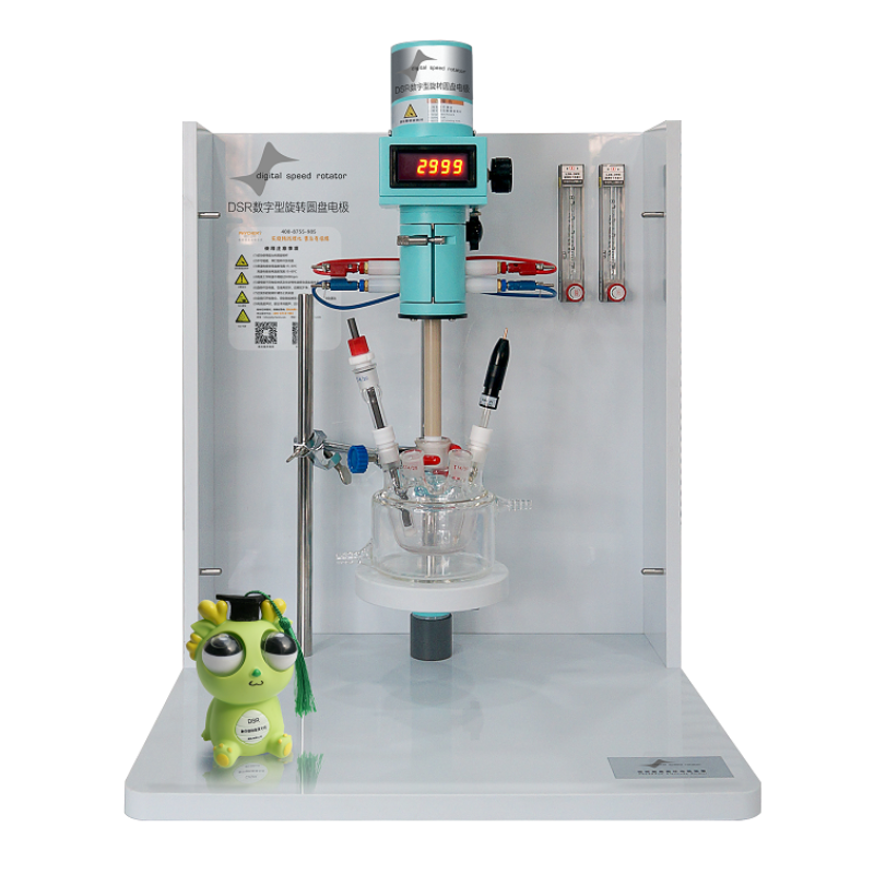
理化(香港)有限公司为您提供《电化学工作站测试燃料电池阴极催化剂ORR极限电流影响因素》,该方案主要用于燃料电池中ORR氧还原极限电流检测,参考标准《暂无》,《电化学工作站测试燃料电池阴极催化剂ORR极限电流影响因素》用到的仪器有DSR数字型旋转圆盘圆盘电极(RRDE)_电催化仪器_武汉电弛。
我要纠错
推荐专场
电化学仪器部件、外设
更多相关方案


 咨询
咨询
