

方案详情文
智能文字提取功能测试中
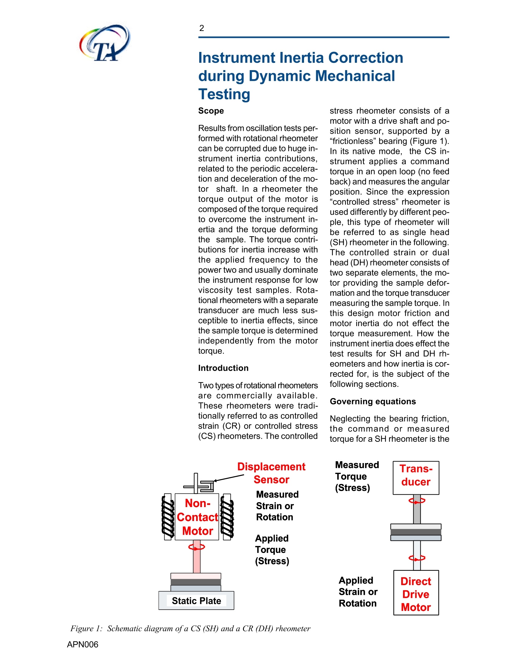
2 Instrument Inertia Correction3 Understanding Instrumentnertia Corrections in Scope Results from oscillation tests per-formed with rotational rheometercan be corrupted due to huge in-strument inertia contributions,related to the periodic accelera-tion and deceleration of the mo-tor shaft. In a rheometer thetorque output of the motor iscomposed of the torque requiredto overcome the instrument in-ertia and the torque deformingthe sample. The torque contri-butions for inertia increase withthe applied frequency to thepower two and usually dominatethe instrument response for lowviscosity test samples. Rota-tional rheometers with a separatetransducer are much less suS-ceptible to inertia effects, sincethe sample torque is determinedindependently from the motortorque. Introduction Two types of rotational rheometersare commercially available.These rheometers were tradi-tionally referred to as controlledstrain (CR) or controlled stress(CS)rheometers. The controlled Displacement Sensor Measured Non- Strain or Applied Torque (Stress) Static Plate stress rheometer consists of amotor with a drive shaft and po-sition sensor, supported by a“frictionless”bearing (Figure 1).In its native mode, the CS in-strument applies a commandtorque in an open loop (no feedback) and measures the angularposition. Since the expression“controlled stress”rheometer isused differently by different peo-ple, this type of rheometer willbe referred to as single head(SH) rheometer in the following.The controlled strain or dualhead (DH) rheometer consists oftwo separate elements, the mo-tor providing the sample defor-mation and the torque transducermeasuring the sample torque.Inthis design motor friction andmotor inertia do not effect thetorque measurement. How theinstrument inertia does effect thetest results for SH and DH rh-eometers and how inertia is cor-rected for, is the subject of thefollowing sections. Governing equations Neglecting the bearing friction,the command or measuredtorque for a SH rheometer is the Measured Trans- Torque ducer (Stress) Applied Direct Strain or Drive Rotation Motor sum of the torque necessary todeform the sample and thetorque to overcome the inertiaas shown in figure 2("). The sam-ple torque M *=M°exp{i(ωt+8)is M=M+M, M三= k M*=-Iom Figure 2: Torque balance for a single head rheometer Meas. torque: Mr(t) sample torque: (G*k)* Figure 3: Torque balance for a dual head rheometer with separatetransducer the product of the material func-tion (here the complex modulus)and the sample deformation, di-vided by the geometry constantk. The inertia torque M * is theproduct of the moment of inertiaI and the angular acceleration.The solution of the torque bal-ance in figure 2 for an imposedsinusoidal torque is as follows: The sample storage modulus G’is the sum of the real part of themeasured modulus and an iner-tia correction term, which in-creases with the test frequencysquared. The loss modulus is notcorrected. The real and the im-aginary parts of the measuredmodulus G* are obtained fromthe measured position p(t)=°cos(ωt+8) and stress M (t)=Mcos(ot) signals, using a crosscorrelation technique(".8 is themeasured phase or raw phase,8 is the sample phase. The torque balance for the DH rheometer is illustrated in figure3. Due to the non-zero trans-ducer compliance C., the sam-ple deformation is the differenceof the angular displacement ofthe motor and the transducershaft. With the transducer com-pliance constant, the complextransducer torque M* is propor-tional to the complex transducerdisplacement *.. Transducerin-ertia contributions are small,be-cause they are related to thetransducer angular displacementp,(t). The solution of the torquebalance for an imposed sinusoi-dal deformation is more complexthan the solution for the SH rh-eometer. and both measuredmoduli, G' and G” have to becorrected for transducer com-pliance (C,) and Inertia (I). Force Rebalance Transducers(FRT) are quasi infinite stifftransducers below a test fre-quency of 100 rad/s and have a low compliance value C, (102rad/Nm for the 1KFRTN1 at 10rad/s). As a consequence thetransducer displacement appro-ches zero and so does the iner-tia term. The motor displacementis now proportional to the sam-ple deformation. o*→0 In this case, the measured lossand storage modulus and thephase angle are true materialquantities. Monitoring InstrumentInertia Effects The best parameter to quantifythe extend of inertia effects onthe measured data is the ratio ofinertia M, to sample torque M,referred to as torque ratio(TR). For DH rheometers, assumingthe transducer scompliance islow and constant,the torque ra-tio depends only on the instru-ment parameters I and C, as: Frequency o [rad/s] Figure 4: Torque ratio for SH andDH rheometers For SH rheometers, the torqueratio depends also on the testsample itself. For a Newtonianfluid, the torque ratio is inverseproportional to the material's vis-cosity. The torque ratio has been cal-culated for both types of rheom-eters as a function of frequencyand is shown in figure 4. For SHrheometers the TR is a functionof the material's viscosity andthe instrument's moment of in-ertia. The torque ratio is equalto 1 (sample and inertia torqueare the same) for the AR-G2 rh-eometer at approximately 1 rad/s for a 6 mPa-s silicone oil. The torque ratio of DH rheometersdepends only on rheometer pa-rameters. Since the FRT trans-ducer is quasi infinite stiff, theinertia torque is orders of mag-nitude lower, than the sampletorque. Note, that above 8 rad/s,the inertia torque increasesstronger. At this point the trans-ducer compliance C. increases.Nevertheless for the standard1KFRTN1 transducer, the contri-bution of inertia torque is onlyaround 2-3% at a frequency of100 rad/s. Since the TR is direct propor-tional to I, it is important for SHrheometers to have a system in-ertia as low as possible. Thetorque ratio for a high inertia sys-tem (90 umNs2) is shown forcomparison in figure 4. Another useful parameter tomonitor the effect of inertia is themeasured (raw) phase angle 8.If only inertia of the drive shaftis present G* =0 (inertia domi-nates), Io² Figure 5: Vector representation ofinertia, measured and correctedmodulus The solution of this equation fora sinusoidal torque inputM* =M sinωt is given as: =Q)²m sin(ωt+飞) The measured phase shift be-tween displacement and torquesignal (raw phase) is 元. Inertiashifts the phase angle to 180°,the phase angle for a Newtonianfluid is 90°. Figure 5 shows the vector rep-resentation of the measured(G* ) and the sample (G*)modulus for SH rheometers. Ifinertia dominates,G'/k and G”/k,go to zero, the term Io2| isequal to |G */k. and 8 is n or180°. The raw phase 8 is an- Figure 6: Complex viscosity of3silicone oils, measured on the other monitor of the inertia con-tributions.Measurements, exhib-iting a raw phase value above175°need to be evaluated verycarefully, as experimental errorsand system corrections aremuch larger than the final testresults. To demonstrate the effects of in-ertia, oscillation measurementson three silicone oils between 3and 1000 mPa-s have been per-formed in the frequency rangefrom 0.1 to 500 rad/s. (Figure 6)The complex viscosity n*= G*/ω obtained with the DH rheom-eter (ARES) is constant over thecomplete frequency range for allthree silicone oils. The SH rh-eometer provides good data forthe 1000 cP oil, but shows a de-viations for the 100 and 3 cP oilat 100 respectively 10 rad/s. Thecorresponding raw phase andcorrected phase for the SH rh-eometer are shown in figure 7.For the 3 cP oil, the raw phasereaches a phase angle of 170°at 1 rad/s already. The correctedphase is wrong above 8 rad/sand the complex viscosity above20 rad/s. What is the reason forthe deviation of the correctedtest results in SH rheometers? Inertia Correction From the equations (1) it is evi-dent, that the instrument inertiacontribution effects the storagemodulus G. The energy to over-come inertia is stored in the mo-mentum of the rotation motorshaft, and is not dissipated. Theincrease of the complex viscos-ity in figure 6 with increasing fre-quency results from strong G'contributions under the giventest conditions. For a more de-tailed investigation, the complexmoduli G'and G”fora 6 mPa-ssilicone oil (S6), were deter-mined in an ARES and AR2000rheometer. For a Newtonianfluid, no G'contributions are ex-pected; as such the G'data ob-tained with the ARES are lessthan 0.1%of the G”values and Figure 7: Raw an corrected phaseangle for 3 silicone oils measuredwith the AR2000. represent system noise. For theAR2000, the measured G'dataare significant and show a pla-teau at low frequency. Above 10rad/s the G’increases with thefrequency to the power 2 andamounts to 20-30% of the com-plex modulusat 100 rad/s. In SH rheometers, the correctionof instrument inertia is orders ofmagnitude higher than for theDH rheometer. If inertia be-comes dominant and the mo-ment of inertia is only slightlyunder corrected, G‘increases ataslope of two with frequency (In-ertia torque depends on the prod-uct of the moment of inertia andthe angular frequencysquared).This is shown for a lowviscosity silicone oil (S6) in fig-ure 9. The instrument, the sam-ple and inertia torque are plot-ted as a function of frequency. Both instrument and sample Figure 8: Dynamic moduli and phase angle for a 6 cPsilicone oil measured with the ARES and AR2000 rheometer torque turn into large numberswith increasing frequency,whilethe sample torque remains smalland is two orders of magnitudelower at 100 rad/s. The correctedphase decreases above 10 rad/s. This means, that G’becomesmore significant and increaseswith a slope of 2 (see also G’ forthe AR2000 in figure 8). In thiscase, inerta contributions areunder-corrected. A slight in-crease of the moment of inertiaI by 0.1% changes the sampletorque by 10% at 100 rad/s andG'even more ("). If the inertia isover-corrected, the samplephase becomes larger tan 90°and G'is negative. In the DH rheometer, the situa-tion is reversed. The inertiatorque is in the order of 5 dec-ades lower than the measuredtorque at low frequency and con-sequently, the sample torque isvirtually identical to the meas-ured torque. (figure 10). Above8 rad/s the inertia torque in-creases faster with frequency(see also figure 4)-this is due tothedecrease of the transducer’sstiffness at higher ferquency. At100 rad/s, the inertia torque isonly 2.7% of the sample torqueand inertia corrections can beneglected. Raw phase and sam-ple phase are the same and stayat 90° throughout the frequencyrange up to 100 rad/s. The impact of inertia contribu-tions is significant when analys-ing weak structures in low vis-cosity fluids. The test sample infigure 11, a printing ink, is ex-pected to have a light structure.In this graph the ink results arecompared to the low viscositysilicone oil S6, measured withthe ARES rheometer. The testtemperature for the silicone oilwas increased to match the vis-cosity of the ink at 20 °C. There-fore the G”data for the ink andthe silicone oil measured on theAR2000 and the ARES rheom-eter superpose very well. Thelowest curve is the G‘of the sili- cone oil and represents a kind ofsystem“G'resolution”. The upperG‘curves are obtained for the ink.Clearly the G‘data are higher then Frequency o [rad/s] Figure 9: Measured, corrected modulus and inertia term for the S6silicone oil measured with the AR2000 cca Figure 10: Measured, corrected modulus and inertia term forthe S6 silicone oisilicone oil measured with the ARES Figure 11: Dynamic moduli for a printing ink measured with ARES andAR2000 for the silicone oil and the dataobtained from the two instru-ments match quite well. This issurprising, considering theamount of correction necessaryfor the SH rheometer. The higherG’response for both SH and DHrheometer supports the exist-ence of a slight structure for theprinting ink. How do SH and DH rheometerdifferentiate for this application? The SH rheometer has to be cali-brated in term of inertia andtorque very carefully to be ableto measure small values of G’of a low viscosity fluid. Slight de-viations will cause significantvariations of the final data-SHrheometers therefore are notreliable for this application.Carefull calibration and verifica-tion with a Newtonian oil is nec-essary. The ARES with FRT transducerdoesn't need any sophisticatedcalibration and inertia correc-tions up to 100 rad/s. Minor er-rors in the system setup param-eters do not significantly effectthe test results. Conclusions The ARES rheometer measuresthe dynamic properties from highto low viscosity up to 100 rad/swithout major correction of thephase angle due to inertia ef-fects. For the AR rheometer thesample response for low viscos-ity materials is only a small frac-tion of the measured G* and avalid data correction can only bedone after careful calibration ofthe system inertia and mappingof the instrument. As such, os-cillation data obtained on nonNewtonian low viscosity fluidscan easily be corrupted. It istherefore an absolute must forSH rheometers to monitor thelevel of correction done to themeasured data. Two parametersare available to be used, the ra-tio of inertia to sample torque orthe measured (raw) phase. Keywords: moment of inertia, inertia corrections, raw phase, controlled stress rheometer, strain controlled rheometer by A.J. Franck, TA Instruments APN Results from oscillation tests performed with rotational rheometer can be corrupted due to huge instrument inertia contributions, related to the periodic acceleration and deceleration of the motor shaft. In a rheometer the torque output of the motor is composed of the torque required to overcome the instrument inertia and the torque deforming the sample. The torque contributions for inertia increase with the applied frequency to the power two and usually dominate the instrument response for low viscosity test samples. Rotational rheometers with a separate transducer are much less susceptible to inertia effects, since the sample torque is determined independently from the motor torque.
关闭-
1/8
-
2/8
还剩6页未读,是否继续阅读?
继续免费阅读全文产品配置单
TA仪器为您提供《材料中震荡测试检测方案(流变仪)》,该方案主要用于材料中震荡测试检测,参考标准《暂无》,《材料中震荡测试检测方案(流变仪)》用到的仪器有TA仪器Discovery流变仪。
我要纠错
相关方案
 咨询
咨询