

方案详情文
智能文字提取功能测试中
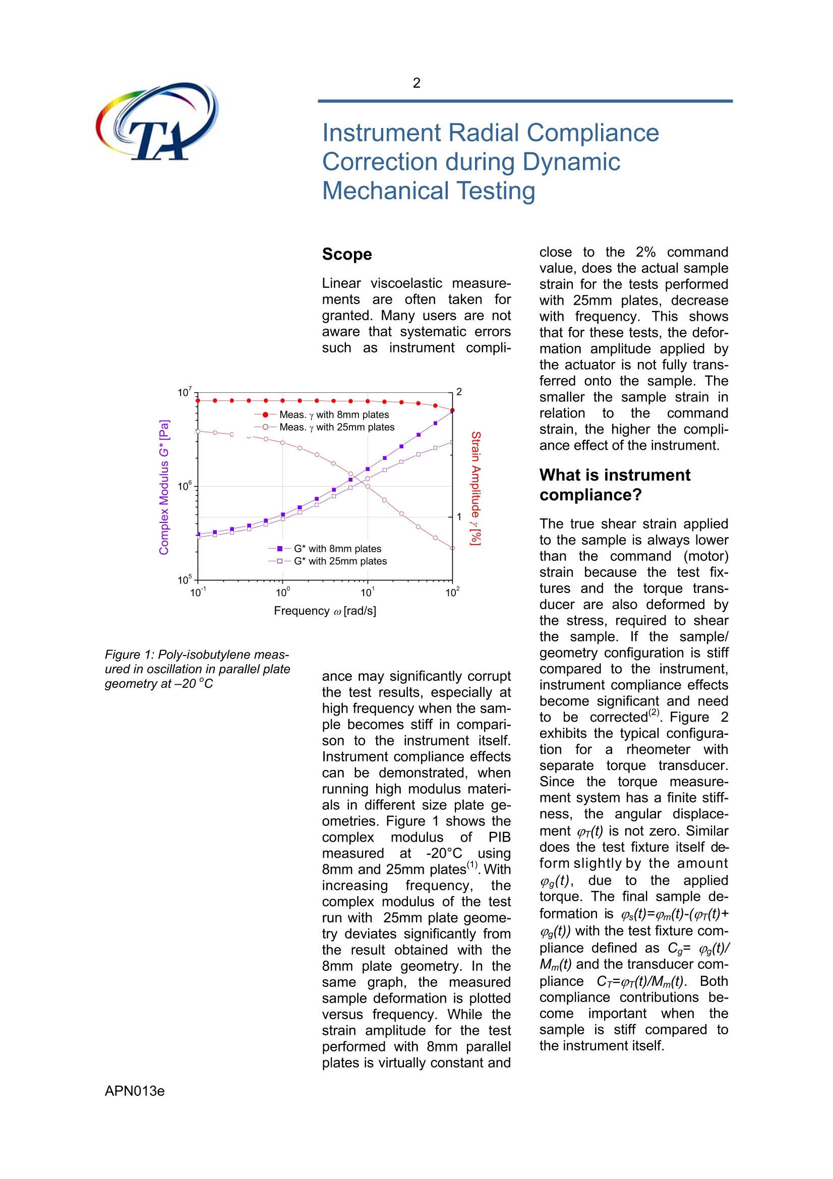
2 Understanding Instrument Compliance Correction Understanding InstrumentCompliance Correction in Power Release by A.J. Franck, TA Instruments Scope Linear viscoelastic measure-mentssiare oftenntaken forgranted. Many users are notaware that systematic errorssuchnasinstrument compli- Figure 1: Poly-isobutylene meas-ured in oscillation in parallel plategeometry at-20°c ance may significantly corruptthe test results, especially athigh frequency when the sam-ple becomes stiff in compari-son to the instrument itself.Instrument compliance effectscan be demonstrated, whenrunning high modulus materi-als in different size plate ge-ometries. Figure 1 shows thecomplexmodulus ofbf PIBmeasuredat·-20°C using8mm and 25mm plates). Withincreasinggfrequency, thecomplex modulus of the testrun with 25mm plate geome-try deviates significantly fromthe result obtained with the8mm plate geometry. In thesame graph, the measuredsample deformation is plottedversus frequency. While thestrain amplitude for the testperformed with 8mm parallelplates is virtually constant and close to the 2% commandvalue, does the actual samplestrain for the tests performedwith 25mm plates, decreasewith frequency. This showsthat for these tests, the defor-mation amplitude applied bythe actuator is not fully trans-ferred onto the sample. Thesmaller the sample strain inrelation to thecommandstrain, the higher the compli-ance effect of the instrument. What is instrumentcompliance? The true shear strain appliedto the sample is always lowerthan the command (motor)strain because the test fix-tures and the torque trans-ducer are also deformed bythe stress, required to shearthe sample. If the sample/geometry configuration is stiffcompared to the instrument,instrument compliance effectsbecome significant and needto be corrected(2). Figure 2exhibits the typical configura-tionfor arheometer withseparate torque transducer.Since the torque measure-ment system has a finite stiff-ness,the angular displace-ment pr(t) is not zero. Similardoes the test fixture itself de-form slightly by the amountPg(t),, due to the appliedtorque. The final sample de-formation is ps(t)=0m(t)-(pr(t)+g(t)) with the test fixture com-pliance defined as Cg=Pg(t)/Mm(t) and the transducer com-pliance Cr=Pr(t)/Mm(t). Bothcompliance contributions be-come important whenthesample is stiff compared tothe instrument itself. Figure 2: Schematical represen-tation of a rheometer with sepa-rate torque transducer Table 1: Compliance correctionfor the dynamic moduli G', G"and loss tan8, 0s=9m-Pg Figure 3: Vector representation ofthe tool compliance Note that the FRT also has anaxial compliance. The axialcompliance does only margin-ally affect the modulus, buthas a significant influence onthetransientnormalforcemeasurement. For both rheometers, AR andARES compliance correctionsarenecessary,when stiffsamples are measured. Sincethe AR has no transducer.only the test fixture compli-ance needs to be corrected. Test fixture compliancein AR & ARES rheome-ters For the AR rheometer and theARES, assuming quasi-infinitestiffness for the transducer-thus transducer deflection isnegligible, the angular dis-placement of the motor andthe sample torque can be rep-resented as vectors in thecomplex plane as shown infigure 3. The total motor angu-lar displacement is m, the testfixture displacement due to thetool compliance Cg is pg. Thetrue angular displacement forthe sample s is the vectorsum. Since Cg is a real number,g isin phaseewith thesampletorque M and not the angulardisplacement 0m. M' M“ Figure 4:Decomposition of thetorque a) in reference to the mo-tor strain vector and b) in refer-ence to the sample strain vector Since S* is the “apparent” stiffnessand Ga* the “apparent” dy-namic modulus; kg the geome- M ys=Pm-r Figure 5: Vector representation of theFRT transducer compliance try constant. Figure 4 showsthe real and imaginary torquecontributions of the apparentmodulus Ga*. The true dy-namic modulus G*is given by: When inserting eqs. (2) and(3) into (1), the true moduluscan be written as: The equations for the truestorage and loss modulus arecalculated 1from (G*=G'+iG”and shown in table 1. Therealand imaginaryytorguecontribution of theetruemodulus G*are shown in fig-ure 4. It should be noted, thatthe tool compliance, also areal number does affect themodulus and the phase of thesample dynamic modulus G*. Transducer compliancefor the ARES rheome-ter The FRT “ForceerebalanceTransducer”iuses a servocontrol to driveetttheupperplate back to its zero position,when a torque is applied").The FRT transducer thereforecani be considered tobequasi-infinite stiff. Howeverduring high frequency testingof stiff samples, the servo willnot correct instantaneously(5),the compliance of the trans-ducer increases and cannotbe neglected anymore. Forthe sake of simplicity, the testfixture compliance is omittedin the following. The true sam-ple deformation can be repre-sented by the difference of themotor and transducer angulardisplacement (Figure 5): Time Figure 6: Real time compliancecorrection in the time domain withor=CrM; r is the trans-ducer angular displacement.In contrast to the tool compli-ance Cg, is the transducercompliance Cr acomplenumber and not in phase withthe torque anymore. Since thephase offset p is not knownand varies with frequency andsample stiffness, it is prefer-able to determine the sampledeformationl p's directly in thetime domainby subtractingthe transducerpr(t) angulardisplacementsfrom the rawmotorgm(t) displacement Figure 7: 1KFRTN1 transducercompliance as a function of thetest frequency (Figure 6). This is referred toas real time compliance cor-rection. The advantage of thisapproach is that the instru-ment compliance is eliminatedduring the raw data sampling.Since it is virtually impossibleto measure the deformation ofthe sample directly, the cor-rection of the test fixture com-plianceehas toDbe imple-mented as discussed in theprevious section. The compliance of the FRTtransducer as a function offrequency is a characteristicof the transducer itself. Figure7 shows the angular displace-ment pr of the 1KFRTN1transducer as a function offrequency for 3 different testscenarios.Thettransducerdisplacement scales with themeasured torque and bottomsout around 20 nrad. This isthe angular position resolutionof the servo encoder. Thetransducer compliance calcu-lated from the transducer an-gular displacement and thetorque, is only a function ofthe oscillation frequency andincreases linearly withhfre-quency and levels off around100 rad/s. At 8 rad/s, the com-pliancee ofithe 1KFRTN1transducer issapproximately10 mrad/Nm. Correction of test fix-ture compliance The test fixture compliancecorrection factor can be de-fined as the ratio of the appar-ent sample stiffness Ga*/kgand the tool stiffness 1/Cg. Ifaccurately known, the toolcompliance canbe readilycorrected with the equationsin table 1. Usually the compli-ance correction is small, butcan become significant whenthe product of sample stiff-ness and test fixture compli-ance is large. In figure 8 the loss modulus isseverely underestimated if the compliance effects are nottaken into account. The errorfor the storage moduluss isrelatively small since the nu- Figure 8: G'and G"of poly-isobutylene measured at -20℃before compliance correction merator of eq.1 in table 1 isalways smaller than Ga’ andthe denominator D is smallerthan 1. Note, that the correc-tion for the loss factor tan8 isnon linear in respect to theapparent loss factor. Since thee samplee sstiffnessdependson thedynamicmodulus and the sample ge-ometry, the geometry can bechosen, such as to eliminate Figure 9: G'and G" of poly-isobutylen measured at-20°Cafter compliance correction instrument compliance. If thesample modulus is below 0.4MPa, the compliance correc-tion for the 1KFRTN1 trans-ducer.when using25mmplates can be omitted. Theplateau modulus Gen for mostpolymers however is higher.With 8 mmplates, themodulus limit is aboutit100times higher i.e. 40 MPa, be-cause the sample stiffness isproportional to the 4 powerof the plate radius: As such, the data obtainedwith 8mm plates in figure 1,represent the true storage andlossmodulus and canbeused to calibrate the compli-ance of the 25mm tool fixture.With eqs.1&2 from table 1, thetool compliance Cg can easilybe calculated using the appar-ent moduli obtained with the25mm plates and the dataobtained with the 8mm platesas true moduli. A tool compli-ance of 77mrad/Nm is ob-tained for the 25mm plate testfixture. The corrected 25mmplate data match very well the8mm plate data, shown in fig-ure 9. The correction of the8mm plate data shows nochange - which implies thevalidation of the FRT trans-ducer correction. Conclusion Neglecting instrument compli-ance can lead to significanterrorss in llinear viscoelasticmeasurements in the plateauand transition region. Withouttool compliance ccorrection.the upper limit for the complexmodulus is 0.4MPa whenusing 25mm plates, 1 mm gapfor the ARES. Tool compli-ance is a common problem forall rheometers, with or withoutseparate torquetransducer.when stiff samples are beingtested. Figure 10 shows the ratio of measured and com-mand strain (FRT compliance)and the ratio of corrected andmeasured strain (Tool compli- conference “New techniquesin1 1Experimental Rheology",Septemberr1985.5,FReading,UK 5. Mackay, M.E.; Halley, P.J.;J.Rheol.35, 1609(1991) Frequency ω [rad/s] Figure 10: Ratio of measured/command strain and corrected/measured strain ance) as a function of fre-quency for the PIB at -20°Cusing 25mm plates, 1mm gap.The ratio representing theFRTcompliance is onlyslightly higher than the ratiofor the tool compliance. Thismeans for the ARES rheome-ter, that when compliance ef-fects are detected and themeasured strain is significantsmaller than the commandstrain, the tool compliancecorrection needs to be activein order to obtain the correctdynamic moduli. The Orches-trator software allows the cor-rection of test fixture compli-ance in addition to transducercompliance from software ver-sion 7.00 on. References 1. Liu, C.Y.; Bailly, C.; Yao,M.L.; Garritano, R.; Franck, A.presented at the SOR in Octo-ber 2006, Portland,Maine 2.. GGottlieb,M.: Macosko.C.W.;Rheol. Acta21, 90(1982) 3.i.Sternstein, S.S.;Adv.Chem. Series 203, 123(1983) 4. Franck, A.; presented at the Keywords: radial compliance, compliance correction, FRT transducer, plateau modulus, compliance OCopyright TA Instruments APN Nov-V
关闭-
1/8
-
2/8
还剩6页未读,是否继续阅读?
继续免费阅读全文产品配置单
TA仪器为您提供《流体中震荡测试检测方案(流变仪)》,该方案主要用于流体中震荡测试检测,参考标准《暂无》,《流体中震荡测试检测方案(流变仪)》用到的仪器有TA仪器Discovery流变仪。
我要纠错
相关方案
 咨询
咨询