方案详情文
智能文字提取功能测试中
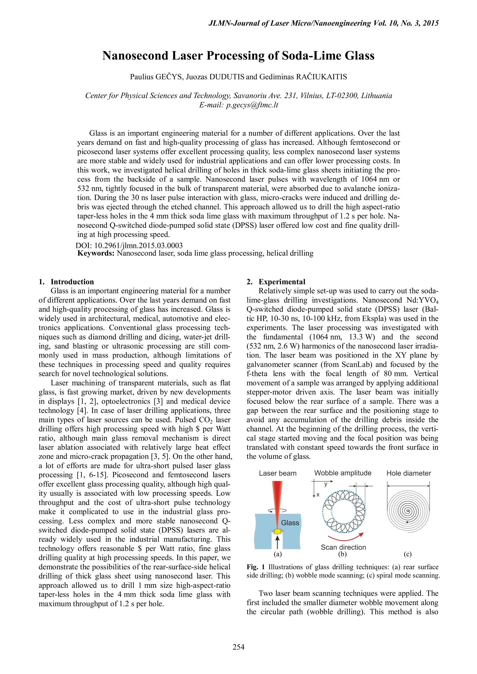
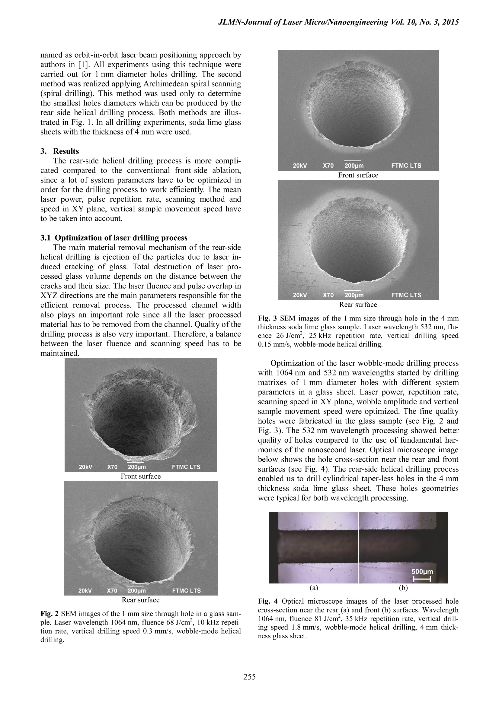
JLMN-Journal of Laser Micro/Nanoengineering Vol. 10, No. 3, 2015 Nanosecond Laser Processing of Soda-Lime Glass Paulius GECYS, Juozas DUDUTIS and Gediminas RACIUKAITIS Center for Physical Sciences and Technology, Savanoriu Ave. 231, Vilnius, LT-02300, LithuaniaE-mail: p.gecys@ftmc.lt Glass is an important engineering material for a number of different applications. Over the lastyears demand on fast and high-quality processing of glass has increased. Although femtosecond orpicosecond laser systems offer excellent processing quality, less complex nanosecond laser systemsare more stable and widely used for industrial applications and can offer lower processing costs. Inthis work, we investigated helical drilling of holes in thick soda-lime glass sheets initiating the pro-cess from the backside of a sample. Nanosecond laser pulses with wavelength of 1064 nm or532 nm, tightly focused in the bulk of transparent material, were absorbed due to avalanche ioniza-tion. During the 30 ns laser pulse interaction with glass, micro-cracks were induced and drilling debris was ejected through the etched channel. This approach allowed us to drill the high aspect-ratiotaper-less holes in the 4 mm thick soda lime glass with maximum throughput of 1.2 s per hole. Na-nosecond Q-switched diode-pumped solid state (DPSS) laser offered low cost and fine quality drill-ing at high processing speed. DOI:10.2961/jlmn.2015.03.0003 Keywords: Nanosecond laser, soda lime glass processing, helical drilling l. Introduction Glass is an important engineering material for a numberof different applications. Over the last years demand on fastand high-quality processing of glass has increased. Glass iswidely used in architectural, medical, automotive and elec-tronics applications. Conventional glass processing tech-niques such as diamond drilling and dicing, water-jet drill-ing, sand blasting or ultrasonic processing are still com-monly used in mass production, although limitations ofthese techniques in processing speed and quality requiressearch for novel technological solutions. Laser machining of transparent materials, such as flatglass, is fast growing market, driven by new developmentsin displays [1, 2], optoelectronics [3] and medical devicetechnology [4]. In case of laser drilling applications, threemain types of laser sources can be used. Pulsed CO laserdrilling offers high processing speed with high $ per Wattratio, although main glass removal mechanism is directlaser ablation associated with relatively large heat effectzone and micro-crack propagation [3, 5]. On the other hand,a lot of efforts are made for ultra-short pulsed laser glassprocessing [1,6-15]. Picosecond and femtosecond lasersoffer excellent glass processing quality, although high qual-ity usually is associated with low processing speeds. Lowthroughput and the cost of ultra-short pulse technologymake it complicated to use in the industrial glass pro-cessing. Less complex and more stable nanosecond Q-switched diode-pumped solid state (DPSS) lasers are al-ready widely used in the industrial manufacturing. Thistechnology offers reasonable $ per Watt ratio, fine glassdrilling quality at high processing speeds. In this paper, wedemonstrate the possibilities of the rear-surface-side helicaldrilling of thick glass sheet using nanosecond laser. Thisapproach allowed us to drill 1 mm size high-aspect-ratiotaper-less holes in the 4 mm thick soda lime glass withmaximum throughput of 1.2 s per hole. 2.Experimental Relatively simple set-up was used to carry out the soda-lime-glass drilling investigations. Nanosecond Nd:YVO4Q-switched diode-pumped solid state (DPSS) laser (Bal-tic HP, 10-30 ns, 10-100 kHz, from Ekspla) was used in theexperiments. The laser processing was investigated withthe fundamental (1064 nm, 13.3 W))and the second(532 nm, 2.6 W) harmonics of the nanosecond laser irradia-tion. The laser beam was positioned in the XY plane bygalvanometer scanner (from ScanLab) and focused by thef-theta lens with the focal length of 80 mm. Verticalmovement of a sample was arranged by applying additionalstepper-motor driven axis. The laser beam was initiallyfocused below the rear surface of a sample. There was agap between the rear surface and the positioning stage toavoid any accumulation of the drilling debris inside thechannel. At the beginning of the drilling process, the verti-cal stage started moving and the focal position was beingtranslated with constant speed towards the front surface inthe volume ofglass. Fig. 1 Illustrations of glass drilling techniques: (a) rear surfaceside drilling; (b) wobble mode scanning;(c) spiral mode scanning. Two laser beam scanning techniques were applied. Thefirst included the smaller diameter wobble movement alongthe circular path (wobble drilling). This method is also named as orbit-in-orbit laser beam positioning approach byauthors in [1]. All experiments using this technique werecarried out for 1 mm diameter holes drilling. The secondmethod was realized applying Archimedean spiral scanning(spiral drilling). This method was used only to determinethe smallest holes diameters which can be produced by therear side helical drilling process. Both methods are illus-trated in Fig. 1. In all drilling experiments, soda lime glasssheets with the thickness of 4 mm were used. 3. Results The rear-side helical drilling process is more compli-cated compared to the conventional front-side ablation.since a lot of system parameters have to be optimized inorder for the drilling process to work efficiently. The meanlaser power, pulse repetition rate, scanning method andspeed in XY plane, vertical sample movement speed haveto be taken into account. 3.1 Optimization of laser drilling process The main material removal mechanism of the rear-sidehelical drilling is ejection of the particles due to laser in-duced cracking of glass. Total destruction of laser pro-cessed glass volume depends on the distance between thecracks and their size. The laser fluence and pulse overlap inXYZ directions are the main parameters responsible for theefficient removal process. The processed channel widthalso plays an important role since all the laser processedmaterial has to be removed from the channel. Quality of thedrilling process is also very important. Therefore, a balancebetween the laser fluence and scanning speed has to bemaintained. Rear surface Fig. 2 SEM images of the 1 mm size through hole in a glass sam-ple. Laser wavelength 1064 nm, fluence 68 J/cm’, 10 kHz repeti-tion rate, vertical drilling speed 0.3 mm/s, wobble-mode helicaldrilling. Front surface Fig. 3 SEM images of the 1 mm size through hole in the 4 mmthickness soda lime glass sample. Laser wavelength 532 nm, flu-ence 26 J/cm , 25 kHz repetition rate, vertical drilling speed0.15 mm/s, wobble-mode helical drilling. Optimization of the laser wobble-mode drilling processwith 1064 nm and 532 nm wavelengths started by drillingmatrixes of1 mm diameter holes with different systemparameters in a glass sheet. Laser power, repetition rate,scanning speed in XY plane, wobble amplitude and verticalsample movement speed were optimized. The fine qualityholes were fabricated in the glass sample (see Fig. 2 andFig. 3). The 532 nm wavelength processing showed betterquality of holes compared to the use of fundamental har-monics of the nanosecond laser. Optical microscope imagebelow shows the hole cross-section near the rear and frontsurfaces (see Fig.4). The rear-side helical drilling processenabled us to drill cylindrical taper-less holes in the 4 mmthickness soda lime glass sheet. These holes geometrieswere typical for both wavelength processing. Fig. 4 Optical microscope images of the laser processed holecross-section near the rear (a) and front (b) surfaces. Wavelength1064 nm, fluence 81 J/cm, 35 kHz repetition rate, vertical drill-ing speed 1.8 mm/s, wobble-mode helical drilling, 4 mm thick-ness glass sheet. 3.2 Drilling speed and quality Drilling process throughput and quality are critical forindustrial applications. Usually laser processing can offerboth, although the high throughput is not always accompa-nied by the high process quality. In case of the rear-sidehelical drilling process, the higher laser fluencies inducedlarger cracks in glass, therefore the lower laser pulse over-lap (higher process speed) was needed to be applied for thematerial removal. The laser-induced crack size determinessurface roughness of the processed hole. Therefore, meas-urements of these laser-affected-area sizes are importantfor the process quality evaluation. Drilling quality was evaluated by measuring the crackssizes at the inner. rear or front surfaces of holes determinedas d and d2 respectively (see Fig. 5). This measurementtechnique was applied for matrixes of holes processed withdifferent laser fluencies and vertical movement speeds of asample. Each matrix included groups of holes drilled withthe same parameters, so the average sizes could be calcu-lated. Only one drilling process parameter was varied be-tween the holes groups in a matrix. Fig. 5 Illustration of the nanosecond laser induced crack sizemeasurements. d determines inner surface crack size, while ddetermines the rear or front surface crack sizes. V,mm/s Fig.6 Relationship between the crack size and vertical drillingspeed for different laser fluencies of 1064 nm wavelength nano-second laser. Solid dots indicate the inner cracking of holes, whileopen dots indicate the crack sizes on the glass front surface. Laserrepetition rate was 30 kHz, 1 mm size holes, wobble-mode helicaldrilling. The high laser fluencies up 93 J/cm from the 1064 nmwavelength nanosecond laser enabled stable drilling pro-cess in relatively wide range of vertical drilling speeds (seeFig. 6). Laser fluence decrease below 44 J/cm resulted innarrowing of the drilling speed window by the factor of 8, although inner crack sizes were reduced from 85 um to63 um at vertical drilling speed of 0.2 mm/s for 93 J/cmand 44 J/cm’ respectively. The front-surface crack sizeswere also reduced from 255 um to 145 um when applyinglower laser fluencies at the drilling speed of 0.2 mm/s.When laser fluence was reduced to less than 38 J/cm, nostable drilling process was observed. At these fluencies itwas enough energy to start the drilling process at the rearsurface, but the drilling stopped at the random distancefrom the top surface and no through holes were fabricatedat any vertical drilling speed. The rear-side helical drilling experiments with the sec-ond harmonics of the nanosecond laser were also per-formed for 4 mm thickness glass sheets. Due to limitationsin our system setup, only maximum laser fluence of26 J/cm could be applied for the drilling investigationswith the 532 nm wavelength. Therefore processing resultswith only 38 J/cm²(1064 nm) and 26 J/cm’ (532 nm) willbe discussed below. Investigations show, that despite relatively low laserfluence at 532 nm wavelength, the broader window interms of vertical drilling speed can be applied for holesmachining (see Fig. 7). The maximum vertical drillingspeed with the 532 nm wavelength was approximately2 times higher compared to 1064 nm drilling and was0.45 mm/s. Surface cracking was also significantly reducedby applying the green radiation processing. The averagefront-surface crack sizes were reduced by factor of 2.5 forthe 532 nm wavelength drilling at the vertical speed of0.2 mm/s. Better processing quality was still observed atthe rear side of the glass where the drilling process wasinitiated first, although, at lower vertical drilling speeds,the difference was insignificant between the front- andrear-surface cracking (see Fig. 7). V,mm/s Fig. 7 Relationship between the surface crack size and verticaldrilling speed for the 1064 nm and 532 nm wavelength of thenanosecond laser processing. The laser repetition rates were30 kHz and 25 kHz respectively,1 mm size holes, wobble-modehelical drilling. 3.3 Maximum process throughput Drilling process speed is very important for industrialapplications. The main material removal mechanism of therear-side helical drilling is ejection of the particles due tolaser induced cracking of glass. Total destruction of laserprocessed glass volume depends on the distance betweenthe cracks and their size. An average laser power takes intoaccount both laser fluence (laser pulse energy) and pulserepetition rate, therefore the drilling speed is mainly influ- enced by this parameter. To determine the maximum holedrilling speed, groups of 1 mm diameter holes were fabri-cated with different settings of the average laser power,pulse repetition rate and vertical drilling speed. Only1064 nm wavelength was applied in these tests since theaverage laser output power at the fundamental radiationwas much higher compared to the second harmonic genera-tion. The maximum drilling speed dependence on the aver-age laser power and repetition rate is shown in Fig.8. Fig. 8 Relationship between the maximum vertical drilling speedand laser power for different pulse repetitions rates of the1064 nm wavelength nanosecond laser, 1 mm size holes, wobble-mode helical drilling. Increase of the average laser power resulted in thehigher drilling throughput. The results also show, that thehigher laser fluencies at lower pulse repetition rate enablesthe faster drilling process with the same average laser pow-er level. This could be explained by larger size crack gen-eration in the glass volume, therefore destruction of thelaser processed glass volume is more efficient. The maximum holesvertical drillingg speedof3.35 mm/s was reached with the average laser power of9.9 W and laser pulse repetition rate of 15 kHz, laser flu-ence 150 J/cm².This enabled us to drill 1 mm holes in 1.2 sper hole with ablation rate of 2.5 mm/s. 3.4 Analysis of drilling process debris Dust and particles after the rear-side helical drillingprocess were collected and investigated with SEM. TypicalSEM view of generated debris after the rear-side helicaldrilling process is shown in Fig. 9. Fig. 9 SEM image of particles generated during the rear-side heli-cal drilling process. Laser wavelength 532 nm, 26 J/cm’, 25 kHzrepetition rate, vertical drilling speed 0.4 mm/s, spiral-mode heli-cal drilling. Broad range of the particle size distribution was ob-served after the laser processing. Larger particles, whichwere clearly visible in SEM image, were measured and theresults are shown in the Fig. 10. Logarithmic relationshipbetween the size of largest particles and vertical drillingspeed was observed. At low vertical drilling speed of0.05 mm/s, smaller particles were generated in the range of130 um. When the vertical drilling speed was increased,particle size started to increase and was in the range of250 um at drilling speed of 0.4 mm/s. V,, mm/s Fig. 10 Relationship between the largest particle size and verticaldrilling speed, laser wavelength 532 nm, 26 J/cm , 25 kHz repeti-tion rate, spiral mode helical drilling. 3.5Minimal hole size The rear-side helical glass drilling process is an effi-cient method for holes fabrication, because laser processedvolume is removed in form of particles. This effect helps toincrease the process efficiency since no laser energy iswasted for material melting and evaporation. The particlesize plays important role in the drilling process, since itdetermines the minimal diameter of the processed hole.The laser processed hole cannot be smaller than generatedparticle sizes, otherwise the debris will block the drillingchannel and the process will stop. The smallest size of ahole, drilled with the 532 nm wavelength of the nanosec-ond laser is shown in the Fig. 11. The minimum diameterwas 200 um. The 532 nm wavelength rear-side helicaldrilling was applied with laser fluence of 26 J/cm, 25 kHzrepetition rate, 0.2mm/s vertical drilling speed, spiralscanning mode. At these processing conditions, the largestparticle siz1n-e of 190 pm was measured after the hole pro-cessing (see Fig. 10), therefore, drilling of smaller holeswas not possible. Fig. 11 SEM image of through hole in 4 mm thickness glass sheet.Laser wavelength 532 nm, fluence 26 J/cm , 25 kHz repetitionrate, vertical drilling speed 0.2 mm/s, spiral-mode helical drilling. The rear-side helical drilling process of soda lime glass. was efficient method for holes fabrication in a 4 mm thick-ness glass sheet with the nanosecond laser. Circular, taper-less holes geometries were processed using this techniqueThe holes quality was controlled by adjusting the laser flu-ence and vertical drilling speed. Surface cracking near thelaser processed hole channel were present in all drillingtests, although at the optimal processing conditions crackswere lowered up to 63 um. Maximum throughput of 1.2 sper hole with ablation rate of 2.5 mm’/s was achieved withavailable system setup. Generated particles limited thechannel size during the drilling process, therefore minimalhole size of 200 um were obtained using this processingtechnique. ( References ) ( [1] D I . A shkenasi, T. Kaszemeikat, N. M ueller, A. Lemke and H. J. Eichler: P roc. Laser A pp lications i n Microelectroni c and O ptoelectronic Manufacturing(LAMOM) XVII, San Fr a ncisco, (2012) p.82430M. ) ( 2]1 M . Sun, U. Eppelt, S. R uss, C. Hartmann,C. Si e bert, JZhu and W . Schulz: Optics Express,21, (2013)7858. ) ( [3] L I . Brusberg, M. Q ueisser, C. Gentsch, H. Schroder and K .-D. L ang: P hysics P rocedia, 39, (2012) 548. ) ( [4] . S S.-F. Tseng, M.-F. Chen, W.-T. Hsiao, C.-Y. Huang, C.. H . Y ang and Y.-S. Chen: O p t. Lasers E n g., 57, ( 2014) 58. ) ( [5] C. K. C hung a n d S. L . L i n: I n ternational J ournal of M achine Tools and Manufacture, 50, (2010) 961. ) ( [6] S . B utkus, E. Gaizauskas, D. P a ipulas, Z. V i burys, D.Kaskelyte, M. B arkauskas, A. Alesenkov a nd V . Sirutkaitis: Appl. Phys. A, 114,(2014) 81. ) ( [7]I D . J. Hwang, T. Y. C hoi and C. P. Grigoropoulos: Appl.Phys. A, 79, (2004) 605. ) ( [8] A. R an, L . Y an, D. Y an-Ping, F. Y ing, Y. Hong and G. Qi-Huang: Chinese Physics L e tters, 21, (2004) 2465. ) ( [9] L . Shah, J. Tawney, M. R ichardson and K. Richardson:Appl. Surf. Sci., 1 83, (2001) 1 5 1. ) ( [10]S. Kivisto, T. Amberla, T. Konnunaho, J. KangastupaandJ. Sillanpaa: Physics Procedia, 41, (2013) 589. ) ( [ 11] S. Ahsam, Y. Y. Kwon, I . S ohn, Y . N oh and M. L e e: J . Laser Micro/Nanoeng., 9 ,(2014) 1 9. ) ( [ 1 2]Y. Shimotsuma,T. Asai, M . Sakakura an d K. Miura: J.Laser Micro/Nanoeng., 9 , (2014) 31. ) ( [13]C. Liu, Y . Liao, F. H e, J. S ong, D. L i n, Y . Cheng, K. Sugioka and K. Midorikawa: J. Laser Micro/Nanoeng.. 8,(2014)170. ) ( [14]J. Gottamann, M. H ermans a n d J . Ortmann: J . L aser M icro/Nanoeng., 8,(2013) 15. ) ( [15]P. N. Wan, C. W. Cheng, H. W. H uang and J. S . Chen:J. Laser Micro/Nanoeng.,7,(2012) 122. ) ( (Received: July 2, 2014, Accepted: May 12, 2015) ) Glass is an important engineering material for a number of different applications. Over the last years demand on fast and high-quality processing of glass has increased. Although femtosecond or picosecond laser systems offer excellent processing quality, less complex nanosecond laser systems are more stable and widely used for industrial applications and can offer lower processing costs. In this work, we investigated helical drilling of holes in thick soda-lime glass sheets initiating the pro-cess from the backside of a sample. Nanosecond laser pulses with wavelength of 1064 nm or 532 nm, tightly focused in the bulk of transparent material, were absorbed due to avalanche ioniza-tion. During the 30 ns laser pulse interaction with glass, micro-cracks were induced and drilling de-bris was ejected through the etched channel. This approach allowed us to drill the high aspect-ratio taper-less holes in the 4 mm thick soda lime glass with maximum throughput of 1.2 s per hole. Na-nosecond Q-switched diode-pumped solid state (DPSS) laser offered low cost and fine quality drill-ing at high processing speed.
关闭-
1/5
-
2/5
还剩3页未读,是否继续阅读?
继续免费阅读全文
北京欧兰科技发展有限公司为您提供《钠钙玻璃中纳秒激光处理加工检测方案(激光产品)》,该方案主要用于建筑玻璃中纳秒激光处理加工检测,参考标准《暂无》,《钠钙玻璃中纳秒激光处理加工检测方案(激光产品)》用到的仪器有纳秒激光器。
我要纠错
相关方案
 咨询
咨询