

方案详情文
智能文字提取功能测试中
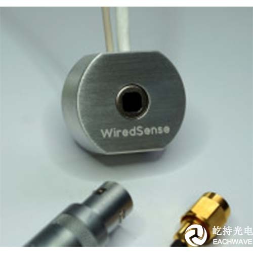
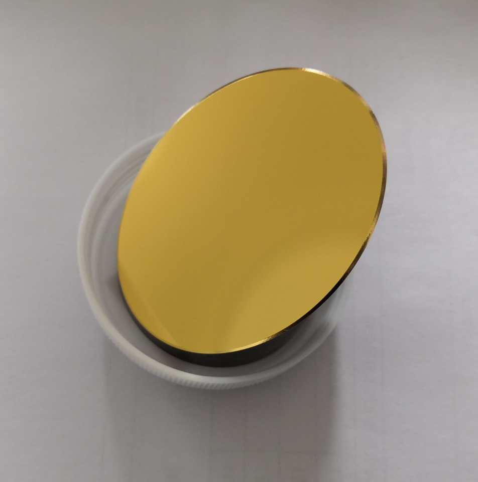
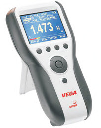
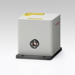
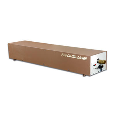
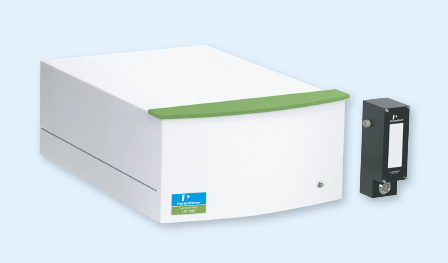
Kit for THz Time-Domain Spectrometer Table of contents 0. Parts for the THz Kit 3 1. Delay line.... 4 2. Pulse generator and lock-in detector.-mm.m: 5 3. .THz antennas 6 4. T3DS software 7 5. Basic steps to build your THz spectrometer 8 6. .Contact details.. 12 0.).Parts for the THz Kit The kit to build your THz Time-Domain spectrometer includes the following items: delay line (linear stage) from Zaber Technologies to match the pulse propagation times ofoptical and THz beam path ● combined pulse generator and lock-in detector based on a data acquisition system fromNational Instruments ● set of two THz antennas (free space or fiber-coupled) laptop with T3DS software to control the delay line and the data acquisition system L.Delay line Zaber Technologies Inc. provides a number of different linear stages, rotary devices and multi-axissystems. The basic BATOP THz kit comes with a T-LSR075A model that has a travel length of 75 mmwhich corresponds to a maximum time delay of 500 ps when using two mirrors on the stage to redirectthe optical beam. Figure 1: Zaber linear stage typically used as delay line in THz spectrometer. The T3DS software can handle all linear stages of the T-LSR and T-LSM series as a delay line but werecommend using type A stages because of the low position error compared to type B and type Ddrives. However, type B and type D stages may be used to build your own imaging stage as theposition error and accuracy will always be much better than the resolution for the focused THz beam(the latter typically being about 1 mm). In order to hook up the delay line to your computer just use the cable and the adapters provided inorder to connect the Mini-Din cable of the stage to a USB port.Once the stage is hooked up and thepower supply is plugged in you can find the stage on one of the COM-ports in the device manager. Ifso, the T3DS software will detect the type of stage automatically upon start-up. For safety reasons you must never put your hand on the stage while it is moving. The linear stage cancause serious damage to your hand and fingers. Hence, before you can change the configuration onthe stage please always disconnect it from the power supply. Pulse generator and lock-in detector In order to create a THz pulse a voltage has to be applied to the emitter antenna. On the right handside of the front panel of the data acquisition system you will find a BNC port that the emitter antennacan be hooked up to. Once the laser pulse hits the gap of the antenna free charge carriers are createdand a very brief current will flow between the contacts, thus creating a THz pulse. The maximumvoltage that the system can put out is 22 V. Figure 2: Data acqusition systems with BNC ports for emitter and detector antenna. When using the T3DS software please make sure that the voltage applied to the emitter antenna isalways within safe limits. Do not exceed the antenna specifications (especially for 1550 nm antennas)! At the detector antenna the THz pulse is converted into a small voltage if the pulse coincides with thelaser pulse. In order to adapt the pulse propagation times the linear stage is moved, changing thelength of the optical path for the emitter antenna (please see Chapter 5). The voltage of the detectorantenna is fed back to the left BNC port on the data acquisition system. During measurements the T3DS software will set the emitter voltage (typically a 10 kHz square wavesignal) and process the signal from the detector antenna. Using the lock-in technique the chosenfrequency is filtered out. Please note, that the signal-to-noise ratio is strongly affected by theintegration time but it may also be limited by the stability of the repetition rate of the laser source. The National Instruments data acquisition system is connected directly to the computer using the USBcable provided. Once hooked up and connected to the power supply you can find the system in thedevice manager. 3.THz antennas The THz kit provided by BATOP comes with either free space or fiber-coupled antennas. The freespace antennas give you the best performance as all elements of the THz path can be alignedindependently. In contrast, the fiber coupled antennas are typically mounted together with thecollimating THz lenses in a lens tube. Focusing lenses may be fixed to this package using another lenstube making it a very simple setup. Figure 3: Set of fiber-coupled antennas setup in a transmission configuration. While the free space antennas will give you the best performance they can not be used for imagingsetups. If you plan on doing imaging measurements it is necessary to use fiber-coupled antennas. Dueto the dispersion in the glass fiber the laser pulse will be broadened on the time scale leading to longerillumination time of the gap and resulting in smaller band width of the THz signal. The extent of thiseffect strongly depends on the length of the fibers. However, there are measure to reduce this effectlike grating-based stretchers. 4.T3DS software The T3DS software allows you to record the signal of the detector antenna while the delay linechanges its position in order to match the pulse propagation times of the optical and the THz beampath. The time-domain graph is updated in real time while the frequency spectrum is calculated anddisplayed once the measurement has been finished. Using the software you can acquire baseline and reference data which may be used in order todetermine material properties of a chosen sample. The baseline and reference data will be savedtogether with the sample data in a single file. While the time-domain data is saved as raw data, thefrequency spectra is calculated after subtracting the baseline and applying the preset window function. Figure 4: Front panel of the T3DS software displaying the results of a reference measurement. When you found a first weak THz signal we suggest using the static measurement mode in order toimprove the signal strength by adjusting the alignment of the optical and THz beam path. Once you aredone optimizing the signal strength you may compare the results of a slow scan with the antennaspecifications. Please note that the antenna data on our website has been acquired with free spaceantennas. If you use fiber-coupled antennas the dispersion in the optical fiber may lead to much longerlaser pulses which can significantly reduce the bandwidth. Hence, you have to compensate this effectusing grating based stretchers or special fibers. The T3DS software has been designed to accommodate external measurement setups as well. If youconnect an imaging unit in a daisy chain configuration to the delay line the software will automaticallyactivate the corresponding tab on the main window upon start-up. For more details please see themanuals for the T3DS software and the external imaging setup. 5.BBasic steps to build your THz spectrometer The THz antennas can be ordered as free space or fiber-coupled versions. Accordingly, there will besome differences in the way you build your spectrometer. However, the basic rules for setting up theoptical and THz beam path are very much the same. ●Choose the configuration and placement of your antennas Since the pulse propagation times have to add up later on it is very important to make surethat the configuration will not be altered. Ideally you will plan for a focusing geometry with afocal length of 30 mm for the THz lenses and place your antennas and collimating THzlenses accordingly. You may remove the focusing lenses and work with a collimated beambut by preparing the setup as described gives you the possibility to add them if neededwithout changing the position of the antennas. This way only the time shift due to the addedmaterial has to be accounted for (typically about 30 ps for a pair of THz lenses). ●Make a first sketch of the optical path for the emitter and detector antenna In general the optical path will start with the laser beam being fed into your setup eitherdirectly or using a collimator (depending on your laser). In the former case we recommendusing a mirror as starting point because a free space laser output will not give you the samealignment options as a fiber-coupled laser which requires a collimator by default. The laser beam will first be split into two paths using a 50:50 beam splitter. The beam goingtowards the emitter antenna is to be redirected by the two mirrors on the delay line at somepoint while the beam going towards the detector antenna should only be redirected bystationary mirrors. This type of setup has proven to yield a better performance than havingthe delay line incorporated into the laser beam for the detector antenna. It was found that thestability of the illumination of the detector antenna is more important than for the emitterantenna. Setting up a preliminary version of your spectrometer according to your sketch Set up the laser and the optical elements as planned and measure the length of the opticalpath for both antennas, starting at the beam splitter. Make sure to position the stage of thedelay line at around 30-40 % of its travel length using the manual knob. Add the length of theTHz path to the optical path of the emitter antenna and try to match it with the length of theoptical path for the detector antenna. Remember to account for the two silicon lenses (each7 mm thick) and the collimating/ focusing THz lenses when calculating the THz path length.In case you need to change the optical path length it is usually easier to modify the part forthe detector antenna. If you use a fiber-coupled setup it is very easy to adapt your configuration as you basicallyjust need to reposition the collimators needed to get the laser pulse into the fibers of yourantennas. For a free space setup you have to bear in mind that the THz beam and the opticalbeam should ideally be collinear. Hence, the last mirrors to redirect the two laser beams andthe antennas have to be in one line. Therefore, you are less flexible when it comes torepositioning optical elements. Figure 5: Exemplary setup of a fiber-coupled THz system. According to Figure 5 the path lengths have to meet the following criteria: with D; and E being the lengths of the free space optical paths, Fp and Fe being the lengths of thefibers and T being the length of the THz path. /Aligning your optical path First off, take out all the optical elements but the one that is used to couple in the laser beam.It is crucial that the laser beam is as parallel as possible to the optical table and that itremains that way all throughout your spectrometer. Hence, start with the collimator / firstmirror and take good care of the correct height by dialing in with an aperture that will then beused for the rest of the setup. After this step put in the beam splitter, check the height and thepower level on both beams. If the power is too high you may use neutral density filters inorder to dial it down. While adjusting the stationary mirrors is very straight forward you have to take great care withthe mirrors on the delay line.We recommend using an additional aperture mounted to thestage because the stage itself has a certain height. Assuming that the laser beam is alreadyparallel to the table you have to make sure that the beam entering the stage is parallel to themovement direction of the stage. Move the stage back and forth and adjust the xy-orientationof the beam at one end and the position of the aperture on the other end. This is an iterativeprocess that can take some time. If you are successful the power of the laser beam behindthe aperture will change less than 5 % while the stage is moved from start to end. Once the beam entering the stage has been aligned correctly put in the first mirror, deflectthe beam by 90° and check the height. Afterwards put in mirror number two, deflect the beam90° and check the height of the beam again. Now use the standard aperture, move the stageback and forth and try to get the power as stable as possible. Again, this is achieved byrepositioning the aperture and changing the xy-orientation of the mirror. The goal is to haveless than 10% change in the power reading behind the aperture during stage movement. In case you use free space antennas the final adjustment is about the two laser beams beingdirected towards the antennas. Start with the antennas and THz lenses being removed (justleave the posts on the table). Cover one of the beams before it hits the last mirror and alignthe other beam to match the positions of the THz antennas. Once this is done block the otherbeam and repeat this procedure. As a result, the two beams should be almost collinear. Final check of the path lengths and last adjustment Now that all optical elements have been put into place move the delay line back to theposition at around 30-40% of its travel length and measure the length of the optical paths forboth antennas. Add the length of the THz path to the result for the emitter antenna andcompare it to the length of the optical path of the detector antenna. If the difference is within1-2 cm you are good to go. If not we recommend repositioning one of the mirrors on thebeam path for the detector antenna and realigning the beam using the same procedure asbefore. Figure 6: Inside of a fiber-coupled spectrometer with the same setup as in Figure 5. ●Illuminating the antennas Depending on your antennas you have to either couple the light back into the collimators orfocus the laser light onto the antennas. In the former case we advise you to use a single mode fiber connecting the collimator withthe power meter. Ideally the fiber is of the same type as the one attached to the antenna(same mode field diameter). Adjust the alignment of the collimator and the last mirror in orderto optimize the coupling. If it does not work with the single mode fiber you may start with amulti mode fiber. After optimization with the multi mode fiber you can change back. Once thepower has been optimized with the single mode fiber, dial the power level to therecommended value, hook up the antenna and watch for the resistance to drop uponillumination. You may need to realign the collimator and last mirror since there is likely to be asmall change in orientation. Aim for a low antenna resistance as it indicates a highillumination. For free space antennas you have to first do a coarse positioning of the antennas in terms ofheight and xy-position. Afterwards adjust the orientation to make sure that the antenna chip isperpendicular to the incoming light (you may need an IR viewer). Next, you can put in theoptical lenses to focus the laser beam. Make sure to choose the correct focal length in orderto get a spot that is roughly the size of the antenna gap (typically 5 pm x 10 pm). Caution: When choosing the focal length and optical power make sure that the pulse fluence of the laser spotdoes not exceed the antenna specifications (see data sheet)! ●Looking for a THz signal Once you are done with the optical alignment put in the collimating THz lenses, hook up yourdelay line and the data acquisition system to the computer / power supply and start the T3DSsoftware. Scan the whole range from 0 to 500 ps using a reasonable step width (comparewith the data of the antennas) and a short integration time (e.g. 0.2 s). Once you have founda signal go to the maximum / minimum and proceed as described in the software andspectrometer manual. Once the frequency spectrum matches the specifications you have successfully set up your THz time-domain spectrometer. If you have any further questions or remarks, please do not hesitate to contact us. BATOP GmbH Wildenbruchstr. 15 D-07745 Jena Germany e-mail: info@batop.de Tel.: +49 3641 634009 0 Fax.:+49 364163400920 如果您已经具备了fs激光器,并且对THz时域光谱系统比较熟悉,Eachwave提供客户自己搭建THz-TDS的所有配件。太赫兹工具箱提供 太赫兹时域光谱仪系统(THz-TDS)中的主要配件, 并且针对系统中的硬件提供相应的控制软件, 我们也可以提供搭建系统的设计方案。主要硬件包括:— 电子盒套装, 包括脉冲电压产生器和锁相探测装置;— 带有准直 TPX 透镜的 THz 天线;— 线性步进电机;— 配套光谱仪软件, 可实现快/慢扫描、成像和角度扫描等,THz 频谱计算分析如计算材料的折射率等。搭建常规THz-TDS,对fs激光器的要求如下:除飞秒激光器外,THz-TDS主要部件有:1,光电导天线:Set of fiber-coupled antennas setup in a transmission configuration2,信号发生器&锁相放大器(Lock in)Data acqusition systems with BNC ports for emitter and detector antenna3, 线性步进电机: Zaber linear stage typically used as delay line in THz spectrometer.4,控制软件T3DSFront panel of the T3DS software displaying the results of a reference measurement自建太赫兹时域光谱系统(光泵浦太赫兹探测系统)系统需要的其他配件晶体(ZnTe、DAST、DSTMS、OH1、LiNbO3)光电导天线(单极天线、天线阵列)近场探针离轴抛物镜斩波器THz脉冲电光取样探测器THz元件(THz偏振片,THz透镜,THz滤波片、THz波片、THz棱镜、THz分束镜等)
关闭-
1/12
-
2/12
还剩10页未读,是否继续阅读?
继续免费阅读全文产品配置单
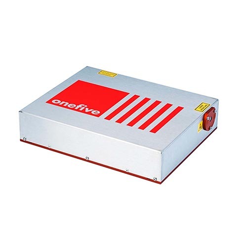
上海屹持光电技术有限公司为您提供《有机物材料中有机物检测方案(激光产品)》,该方案主要用于医疗/卫生中有机物检测,参考标准《暂无》,《有机物材料中有机物检测方案(激光产品)》用到的仪器有Origami飞秒锁模光纤激光器NKT Onefive、一种可以用在真空腔中的太赫兹探测器、 离轴抛物镜 其他光谱配件。
我要纠错
推荐专场
相关方案
 咨询
咨询