

方案详情文
智能文字提取功能测试中
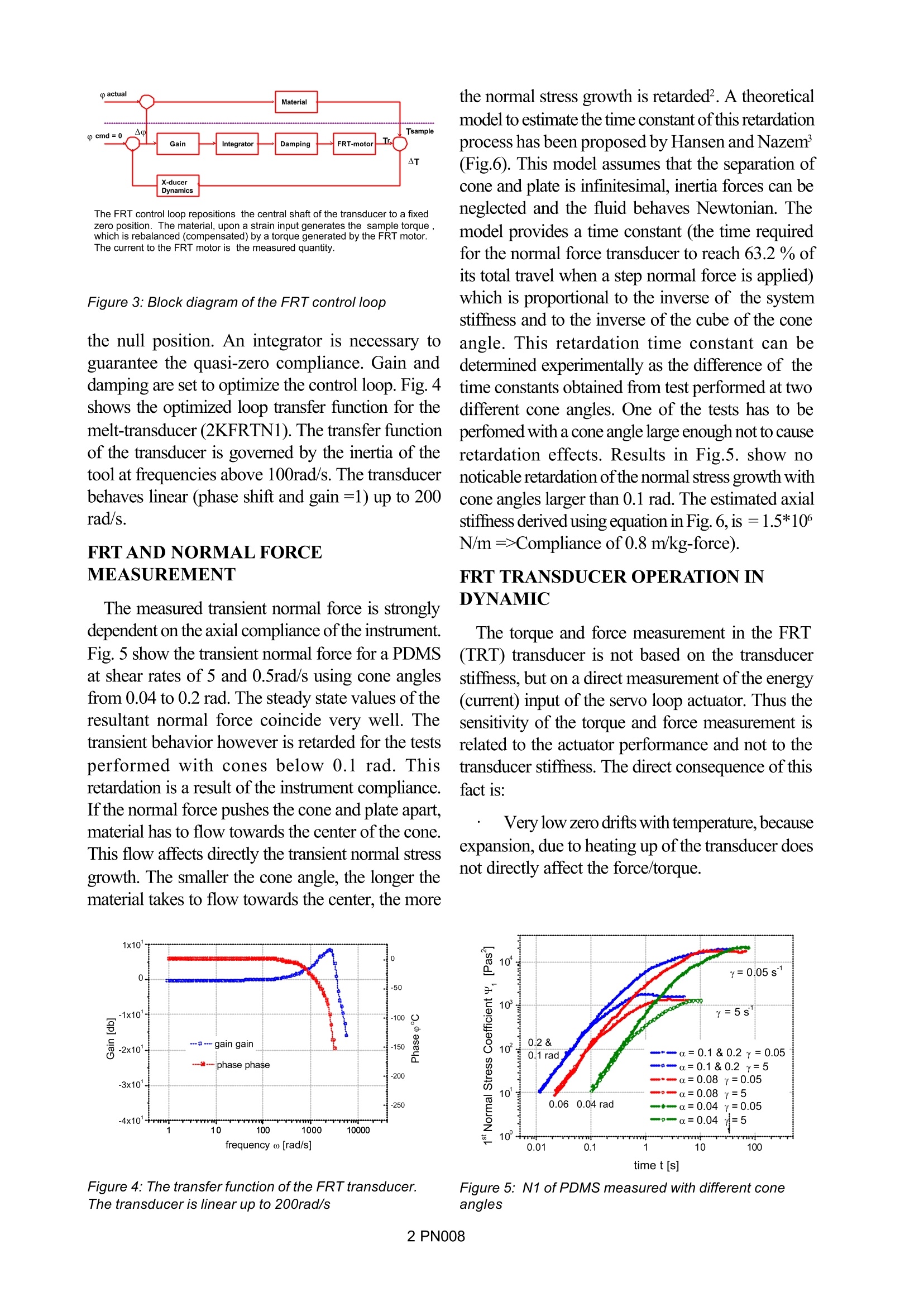
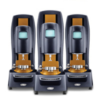
PN008 Keywords: ARES,FRT technology, non-compliant transducer FRT transducer A.J. Franck, TA Instruments INTRODUCTIONI Conventional transducers measure the strain in acompliant member and based on their stiffness,determine the torque resp. normal force (Fig. 1a).This method has several inherent disadvantages.Since the compliant member is strained, the strainhas to be accounted for in determining actual samplestrain. In dynamic the inertia of the moving mass ofthe transducer, affects the measured results at highfrequences. Further, viscoelastic materials whichdevelop normal forces, drive the cone and plateapart. This effect generates secondary flow fieldsand the result is an inaccurate transient normal forcemeasurement. To overcome these problems ofconventional transducer, all developments have beenmade towards stiffer transducers. The stiffnesshowever is directly related to the resolution of thestrain measurement ofthe compliant member i.e. thetorque resp. force measurement. This implies thatthe stress resolution decreases with increasingstiffness. The force/torque rebalance transducer is uniquein that it does not use any compliant members tomeasure force, but rather uses two position controlservos which drive the plate back to its original ornull position (Fig. 1b). This transducer uses speciallydesigned Low Mass, quick response servos, withan extremely wide dynamic range. OPERATION Fig. 2 shows a schematic of the torque/forcerebalance transducer. The capacitive position sensorallows a very accurate measurement of the angularposition. A torque applied to the upper tool by thesample will force the sensor out of the null position. Figure1a &b: Design concept of f a force/ torquetransducers 1 The actuator generates a reaction torque to drivethe tool back to the original position. The absolutevalue of the torque generated by the motor is equalto the torque applied by the sample if friction isnegligible. The stiffness of the transducer is now afunction of the resolution of the position sensor andthe response time of the control loop. The normalforce is measured similar to the torque. The block-diagram of the servo control loop is schematicallyrepresented in Fig.3. T is the torque applied by thesample to the tool. T represents the torquegenerated by the actuator to hold the upper tool in Figure 2: Schematics drawing of the FRT The FRT control loop repositions the central shaft of the transducer to a fixed zero position. The material, upon a strain input generates the sample torque, which is rebalanced (compensated) by a torque generated by the FRT motor. The current to the FRT motor is the measured quantity. Figure 3: Block diagram of the FRT control loop the null position. An integrator is necessary toguarantee the quasi-zero compliance. Gain anddamping are set to optimize the control loop. Fig.4shows the optimized loop transfer function for themelt-transducer (2KFRTN1). The transfer functionof the transducer is governed by the inertia of thetool at frequencies above 100rad/s. The transducerbehaves linear (phase shift and gain =1) up to 200rad/s. FRT AND NORMAL FORCEMEASUREMENT The measured transient normal force is stronglydependent on the axial compliance of the instrument.Fig. 5 show the transient normal force fora PDMSat shear rates of5 and 0.5rad/s using cone anglesfrom 0.04 to 0.2 rad. The steady state values oftheresultant normal force coincide very well. Thetransient behavior however is retarded for the testsperformed with cones below 0.1 rad. Thisretardation is a result of the instrument compliance.If the normal force pushes the cone and plate apart,material has to flow towards the center of the cone.This flow affects directly the transient normal stressgrowth. The smaller the cone angle, the longer thematerial takes to flow towards the center, the more Figure 4: The transfer function of the FRT transducer.The transducer is linear up to 200rad/s the normal stress growth is retarded. A theoreticalmodel to estimate the time constant of this retardationprocess has been proposed by Hansen and Nazem’(Fig.6). This model assumes that the separation ofcone and plate is infinitesimal, inertia forces can beneglected and the fluid behaves Newtonian. Themodel provides a time constant (the time requiredfor the normal force transducer to reach 63.2 %ofits total travel when a step normal force is applied)which is proportional to the inverse of the systemstiffness and to the inverse of the cube of the coneangle. This retardation time constant can bedetermined experimentally as the difference of thetime constants obtained from test performed at twodifferent cone angles. One of the tests has to beperfomed with a cone angle large enough not to causeretardation effects. Results in Fig.5. show nonoticable retardation ofthe normal stress growth withcone angles larger than 0.1 rad. The estimated axialstiffness derived using equation in Fig. 6, is =1.5*10N/m=>Compliance of 0.8 m/kg-force). FRT TRANSDUCER OPERATIONINDYNAMIC The torque and force measurement in the FRT((TRT) transducer is not based on the transducerstiffness, but on a direct measurement of the energy(current) input of the servo loop actuator. Thus thesensitivity of the torque and force measurement isrelated to the actuator performance and not to thetransducer stiffness. The direct consequence of thisfact is: Very low zero drifts with temperature, becauseexpansion, due to heating up of the transducer doesnot directly affect the force/torque. Figure 5:N1 of PDMS measured with different coneangles Figure 6: System reponse measured with two differentcone angles Good dynamic response (up to the maximumfrequency of the servo loop) independent of the fore/torque sensitivity range. Fig. 7 shows the dynamic response of the FRT,plotted as complex viscosity h*(w) up to themaximum frequency of 100 rad/s for a 100 P siliconeoil. No deviation from the Newtonian behavior dueto transducer inertia can be detected for this lowviscous fluid. This allows the measurement of weakstructures in low viscous systems (fruit juices,beverages, etc..), otherwise nearly impossible todetermine quantitatively. CONCLUSION The force/torque rebalance transducer has somemajor advantages over conventional transducers. Due to the very small compliance of the systemno correction for the strain is necessary. The FRT operation is based on thecompensation of forces and-thus has an extremely Figure 7: Frequency scan on a 10 cP silicone oi/ wide dynamic range (0.002mNm to 0.2Nm for the2KFRTN1). This wide dynamic range allows themeasurement of viscosity and modulus over a muchwider range without changing transducers or thegeometry. Due to the fact, that the force/torquemeasurement is not tied to the transducer stiffness.temperature drifts of the zero in torque and normalare virtually non existent. However temperaturefluctuations in the sample, as a result of insufficientT-stability, cause density fluctuations which aremeasured as normal force. This effect increasesinstrument stiffness. Infinite stiffness of the rheometerin axial direction would make normal forcemeasurements impossible, as small T-fluctuationswould cause the normal transducer to overload. The FRT transducer is quasi infinitive stiff with aminimum compliance to allow accurate normal forcemeasurements on polymer melts with a temperaturecontrol of better than 0.1C in the sample. The FRTis a compromise in terms of stiffness with bettersensitivity, lower temperature drift and superiordynamic response than conventional transducers. REFERENCES 1. Franck, A. presented at the Conference,,Newtechniques in experimental rheology"Reading,UK, September 1985 2. Meissner,J. J.Appl.Polym.Sci. 16,2877,(1972) 3. Nazem, Hansen,J.Appl.Polym.Sci.:20, 1355(1976) PN Conventional transducers measure the strain in a compliant member and based on their stiffness, determine the torque resp. normal force (Fig. 1a). This method has several inherent disadvantages. Since the compliant member is strained, the strain has to be accounted for in determining actual sample strain. In dynamic the inertia of the moving mass of the transducer, affects the measured results at high frequences. Further, viscoelastic materials which develop normal forces, drive the cone and plate apart. This effect generates secondary flow fields and the result is an inaccurate transient normal force measurement. To overcome these problems of conventional transducer, all developments have been made towards stiffer transducers. The stiffness however is directly related to the resolution of the strain measurement of the compliant member i.e. the torque resp. force measurement. This implies that the stress resolution decreases with increasing stiffness.
关闭-
1/3
-
2/3
还剩1页未读,是否继续阅读?
继续免费阅读全文产品配置单
TA仪器为您提供《流体中流变检测方案(流变仪)》,该方案主要用于流体中流变检测,参考标准《暂无》,《流体中流变检测方案(流变仪)》用到的仪器有TA仪器Discovery 流变仪。
我要纠错
相关方案
 咨询
咨询