方案详情文
智能文字提取功能测试中
Supplementary Information for S8. The screening effect of 3-5layer graphene on PET Mechanism of Electric Power Generation from Ionic Droplet Motion onPolymer Supported Graphene Shanshan Yang’t, Yudan Sult, Ying Xu’, Qiong Wu', Yuanbo Zhang12, Markus B. Raschke’,MengxinRen, Yan Chen, Jianlu Wang, Wanlin Guo, Y. Ron Shen and Chuanshan Tian1,2,* ’ Department of Physics, State Key Laboratory of Surface Physics and Key Laboratory of Micro- and Nano-PhotonicStructures (MOE), Fudan University, Shanghai, 200433,China 2 Collaborative Innovation Center ofAdvanced Microstructures, Nanjing, 210093, China 'Department of Physics, Department of Chemistry, and JILA, University of Colorado, Boulder, CO 80309, UnitedStates “School of Physics and TEDA Applied Physics Institute, Nankai University, Tianjin, 300071, China 'National Laboratory for Infrared Physics,Shanghai Institute of Technical Physics, Chinese Academy of Science,Shanghai, 200083, China 'Institute of Nanoscience, Nanjing University ofAeronautics and Astronautics, Nanjing 210016, China. 'Department of Physics, University ofCalifornia, Berkeley, CA 94720, United States * Corresponding author: cstian@fudan.edu.cnt These authors contributed equally to this work. Abstract Graphene-based electric power generation that converts mechanical energy of flow of ionic droplets over thedevice surface into electricity has emerged as promising candidate for a blue-energy network. Yet the lack ofa microscopic understanding of the underlying mechanism has prevented ability to optimize and control theperformance of such devices. This requires information on interfacial structure and charging behavior at themolecular level. Here, we use sum-frequency vibrational spectroscopy (SFVS) to probe the interfaces ofdevices composed of aqueous solution, graphene and supporting polymer substrate. We discover that thesurface dipole layer of the polymer is responsible for ion attraction toward and adsorption at the graphenesurface that leads to electricity generation in graphene. Graphene itself does not attract ions and only acts as aconducting sheet for the induced carrier transport. Replacing the polymer by an organic ferroelectric substratecould enhance the efficiency and allow switching of the electricity generation. Our microscopic understanding of the electricity generation process paves the way for the rational design of scalable and more efficientdroplet-motion-based energy transducer devices. Introduction The graphene-electrolyte interface has been demonstrated to exhibit promising attributes as platform for arange of energy devices, such as solar cells, super-capacitors?, and lithium-ion batteries. Notably, a prototypeof a novel graphene-based electric generator has recently been invented using a graphene-liquid interface toconvert mechanical energy of moving ionic droplets to electric energy; it offers an attractive new scheme forscalable electric power generation.4-14 In such a device, droplets or waves of an ionic solution moving acrossgraphene supported by an appropriate substrate generate a current in graphene along or opposite to the flowdirection.More recently, such effect can also be observed at the aqueous interface with a polymer coatedinsulator-semiconductor structure.15 Macroscopically, the governing mechanism of such electrokineticphenomenon can be explained by a drawing potential model. It suggests that selective ions from solution canadsorb at the solid/solution interface and form a pseudo capacitor with the solid. As an ionic droplet movesalong a graphene surface, ions that tend to adsorb on the interface are attracted towards the advancing front(charging of the pseudo capacitor) or repelled from the receding edge (discharging of the pseudo capacitor).Concurrently, oppositely charged carriers in graphene are attracted to the advancing and receding edge,resulting in a current flow in graphene. Thus how effectively ions can be attracted to the interface determinesthe efficiency of electricity generation. On the microscopic scale, however, there are still arguments on theunderlying mechanism that attracts ions to the solution/graphene interface.5,8,9,16,17 This current lack ofmicroscopic understanding hinders our ability to optimize and control the performance of such graphene-based energy transducers. Most work to date has been focused on polymer-supported graphene devices. No consensus has beenreached on the fundamental question of how the interface attracts the electrolyte ions to graphene surface.Several mechanisms have been proposed. Based on density functional theory (DFT) calculations, somesuggest that cations (Na*) from electrolytic solution would preferentially adsorb on graphene 5,16,17 Othersbelieve that a polymer substrate could be pre-charged by various means during sample preparation, forexample, through friction before transferring of graphene on it; the pre-charged polymer could attract ionsfrom solution to graphene since field screening by the monolayer graphene is weak. 8 For future developmentof such devices, it is imperative to pinpoint the mechanism ofion-substrate interaction and learn about the relevant parameters. This requires a molecular-level interfacial study of the device, and sum-frequencyvibrational spectroscopy (SFVS) is known to be a unique analytical tool for liquid/solid interfaces. We report here a SFVS study on polymer-supported graphene-based electricity generation devices. FromSF vibrational spectra of polymer surfaces, solution/polymer interfaces, and solution/graphene/polymerinterfaces, we find conclusively the following: Ions from the solution are not attracted by graphene; they areattracted to graphene/polymer, or polymer without graphene, by surface dipoles of the polymer; the monolayergraphene appears as a weak screening layer for the dipole field and serves as a passive conductive path for thegenerated current; and the interaction between ions and the surface dipole layer is of short range. Our resultsprovide a more comprehensive picture ofelectricity generation by the electrolytic solution/graphene/polymerdevices that would help in future design of such devices for better efficiency and switchable operation. Electricity generation by moving droplets on graphene: dependence on supporting polymer. Figure 1a describes the device and the experimental arrangement in our study. To avoid complication causedby possible contamination of graphene,20 we developed a new method, different from the traditional ones,to lay graphene on polymer. The procedure is described in Method and Fig. S1 of the Supporting Information(SI). Poly-ethylene terephthalate (PET), poly-methyl methacrylate (PMMA), and poly-vinylidene fluoride(PVDF) were studied in our experiment. To test electricity generation of the device, we adopted the falling droplet scheme (Fig. 1b).Successivedrops of 600mM NaCl solution, 5mm in diameter, were let to roll down the graphene surface of the device,which was tilted 60° with respect to the horizontal. Their initial speed on graphene was controlled by theheight H (Fig. 1b), set at 10 cm. Voltage pulses generated across the graphene by the moving drops wererecorded by an oscilloscope. As seen in Fig 1c, positive voltage spikes (corresponding to positive ions attractedto the water/graphene interface) generated by sequential drops on graphene/PET were readily observed, butwere not detectable on graphene/PMMA. This result clearly suggests that it is the polymer substrate, ratherthan graphene, that attracts ions to the water/graphene interface, and PET attracts Na much more stronglythan PMMA. a Figure 1 Electric power generation in polymer supported graphene device. (a) Experimental arrangement for electricitygeneration and SFVS measurements on a device composed of a graphene/polymer film supported by a SiO2 plate. (b) Cartoondescribing the measurement of voltage generation by a falling aqueous drop rolling on the graphene/polymer device. (c)Oscilloscope traces showing presence and absence of voltage spikes generated from graphene/PET (red) and graphene/PMMA(blue, offset for clarity), respectively. The drops were from a 600mM NaCl aqueous solution. SFVS probing of surface field induced by adsorbed ions at the interfaces Sodium ion adsorption at the interface of water in contact with graphene/polymer can be monitored bySFVS. It is known that a surface field at a water interface can reorient water molecules in the interfacial layer,and result in a spectral change that can be detected by SFVS.22-28 The spectroscopic technique measures theOH stretch spectrum of the effective surface nonlinear susceptibilityxof the interfacial water, which hasthe expression29,30 where xs’denotes contribution from a few monolayers of water molecules right at the interface, the integraldescribes the contribution from field-induced polarization of water molecules in the diffuse layer, Epc(z) isthe distance dependent surface field along the surface normal,x) ddenotes the third-order nonlinearsusceptibility of bulk water, and Ak is the phase mismatch of the SFVS process. The change of xser(@), inparticular Im Xs.er(@), directly reflects the change of Epc(z) in both magnitude and direction. Figure 2. Bonded OH stretch SFVS spectra of interfacial water.(a) and (b) SF intensity spectra from the interfaces of NaCl(aq.)/PMMA and NaCl(aq.)/graphene/PMMA, respectively, for a set of different NaCl concentrations in the solution.The nearly identical spectra for all concentrations indicate that both interfaces are essentially neutral, with no ion adsorption.In contrast, the SF intensity spectra from the interfaces of (c) NaCl(aq.)/PET and (d) NaCl(aq.)/graphene/PET increase withNaCl concentration, indicating an increasing density of ions at the interfaces. A small field screening effect of graphene is21seen from the lower spectral intensity in (d) in comparison to (C). The Im Xs,er spectra for (e) NaCl(aq.)/PET and (f)NaCl(aq.)/graphene/PET interfaces, deduced from the corresponding SF intensity spectra in (c) and (d) and discrete phasepoints in (e) and (f) measured directly by phase-sensitive SFVS, become increasingly negative with increasing NaClconcentration, indicating an increasing amount of Naions adsorbed at the interface. We conducted SFVS measurements on solution/polymer and solution/graphene/polymer interfaces. Theexistence of a surface field created by PET, but not by PMMA, can be seen from the spectral variation withincreasing salt concentration in water. Ions in water can move toward the water interface in response to thesurface field and modify the field. Figure 2a-d displays the spectra for the four aforementioned interfaces withdifferent salt concentrations in water ranging from 0 to 600mM. Within measurement error, the spectra ofwater/PMMA and water/graphene/PMMA are independent of the salt concentration (Fig. 2a and 2b).Obviously, ions do not come to the interface to alter the interfacial water structure. This is a clear manifestation that neither graphene nor PMMA attracts ions. The case of PET is different. The spectrum changessignificantly with salt concentration (Fig. 2c and 2d); Na ions must have come to the interface to perturb thewater structure. The spectrum of the water/graphene/PET interface at each salt concentration is slightly lowerthan that of the water/PET interface, indicating a weak screening effect of graphene. The positive ion attraction to graphene was speculated to be caused by pre-existing negative surfacecharges on the substrate before graphene was transferred onto it." However, knowing that Nat ions do notspontaneously adsorb on graphene, a negative surface charge layer on the polymer that attracts Na wouldhave set up an electric double layer (EDL) with a negative surface field in the adjoining water and makeIm xser more positive. In contrast, a close look a2)t the Im Xserspectra of the water/P l andwater/graphene/PET interfaces for different salt concentration in water reveals that they become more negativeat higher salt concentration (Fig.2e and 2f).31 This means that the surface field is positive and increases withsalt concentration, orienting the interfacial water molecules with O→H more toward the bulk water, oppositeto what is expected from a negatively pre-charged surface. This observation can only be explained byadsorption of Na ions at the interface creating a positive surface field. Origin of ion adsorption at the interface With pre-existence of negative surface charges on PET out of the question, what is then the origin of Naion adsorption at the interface? The surface of a polymer can often be polar with certain molecular grouppolar-oriented at the surface. If the group has a strong dipole, the polymer should possess a strong surfacedipole layer that can attract ions. SFVS can be used to learn about the polar surface structure of a polymerburied under graphene. For PMMA with a chemical formula [CH2=C(CH3)CO2CH3]n, it has been found thatthe side chains -CO2CH3 dominate on the surface with CH3 projected out at 30°from the surface normal.However, CH has a very weak dipole and accordingly, PMMA has a very weak surface dipole layer. Incontrast, PET with [C:H:(CO2)2]n has the carbonyl groups (C=O) normally protruding out of the surface.Because C=O has a very strong dipole, PET has a strong dipole layer. Figure 3a shows the C=O stretch spectraofPMMA and PET surfaces covered by graphene, obtained by SFVS. The very prominent C=O peak at ~1725cm for PET illustrates the strong polar ordering of C=O on the PET surface, while the undetectable C=Opeak for PMMA indicates little polar ordering of C=0 along the surface normal. The surface dipole layer ofC=O with O pointing out on PET must be responsible for attraction of Na to the water/graphene interface. Now the question is how a surface dipole layer can attract Na from solution to adsorb on graphene/PET.It is well known, from the continuum theory of electrostatics, that an infinite continuum of surface dipole layerhas no field outside the layer. In reality, however, surface dipoles associated with molecular groups reside atdiscrete positions on the surface. As pointed out by Cherepanov et al., while such local dipoles are of veryshort range, they create a local potential well on top of each dipole that can trap ions.34 For illustration, weplot, in Fig. 3b, the calculated potential distribution created by a square array of surface dipoles with a surfacedensity equal to that of C=0 on PET (see SI for details). Positive ions adsorbed in the potential traps, nowplay the dominant role in setting up the positive surface field and the electric double layer in water at theinterface. Because the surface dipole field is of short range (see Fig. 3b), the screening effect of graphene canbe appreciable. Accordingly, ion adsorption decreases significantly with increase of the graphene layerthickness. This is illustrated in Fig. 3c, where it is seen that the increase of the SF signal with ion concentrationis much less for the 3-5 layer graphene/PET than for the monolayer graphene/PET. Figure 3 Origin of ion adsorption at water/graphene/PET interface.(a) SF vibrational spectra showing the absence andpresence of the C=0 stretching mode at the graphene/PMMA and graphene/PET interfaces, respectively, denoting strongC=0 polar ordering on the latter interface. (b) Calculated azimuthally isotropic electric potential in the x-y plane generatedby a square array of C=O dipoles with C→O pointing normally toward the solution. It appears as highly localized potential wells that can trap positive ions.(c) Relative increase of SF signals for monolayer and 3-5 layers of graphene/PET devicesversus NaCl concentration. The SF signals are normalized against that of pure water. (d) Surface Na density versus bulkNaCl concentration deduced from the Im 2)spectra using the Gouy-Chapman model. Fitting of the data points by a simpleLangmuir isotherm, with the surface dipole density taken as the saturated ion density Osat, allows the deduction of theadsorption free energyAG. (e) Cartoon illustrates the motion of ions in solution and electrons in graphene toward the frontedge of the droplet in response to an ionic droplet moving forward with velocity v. The adsorption energy of ions in the surface dipole traps is expected to be small for the C=O type surfacedipoles. We can have an estimate on the adsorption energy from the observed spectral variation of interfacialwater with different salt concentrations. As seen in Eq.(1), in the limit of low surface density of adsorbed ions(Na), only the second term on the right depends on the surface field Epc(z), which is generated by theadsorbed ions. With the help of the Gouy-Chapman model, we can relate Epc(z) to the surface ion density o,and use it as an adjustable parameter to calculate AIm xs.ef =Im[Xs,er-XS]=ImXB EDc(z)ei- dz nfit the measured AImXs.er with knownx. (SI). We can thus find o for the different bulk ionconcentrations specified in Fig. 2. The data points are plotted in Fig. 3d and fitted by a simple Langmuiradsorption isotherm with the assumption that the saturated surface ion density, Osat, is equal to the C=O surfacedipole density on PET (0.235/nm).35 From the fit, we find an adsorption energy of AG= -9 (±2) kJ/mol (seeSI). This adsorption energy is indeed a few times smaller than the usual adsorption energy for molecularspecies adsorbed at an interface from solution. General consideration for optimization and possible gate control on electricity generation devices. From what we learned about NaCl(aq.)/graphene/polymer interface, we can come up with the followinggeneral picture (sketched in Fig. 3e) for electricity generation by such devices. Ions in water are attracted tographene by the surface dipole layer, if present, of a polymer and tend to adsorb in the interfacial dipolepotential traps. As a drop of ionic solution moves on graphene, the fresh water/graphene interface is formedat the advancing water front. Sodium ions must rush over to the fresh interface. They increase the potentialseen by electrons in graphene and attract them toward the fresh interface. Only in delayed action, the negativeions in the solution are dragged along by the positive ions and affect somewhat the current in graphene. This dynamic process constitutes the charging action. The opposite process occurs at the trailing edge of the dropand constitutes the discharging action. As proposed earlier, electricity generation results from combinedactions of charging and discharging. The above picture suggests that polymers with a denser and strongersurface dipole layer should be more efficient in generating electricity. A quick estimate (described in SectionS5 in SI) shows that the generated current can be increased by ~10 folds if dipole moment is doubled and itssurface density is four times larger than that of C=0 in PET. Besides it is already known that larger drop size,faster drop velocity, and higher salt concentration generally enhance the current generation, while electricitygeneration also varies with the type of ions in solution as the dynamics of ion motion depends on the size andcharges of the ions.' It may happen that the surface dipole layer of a polymer is so strong that ions adsorbing on it (or on grapheneof the graphene/polymer film) do not desorb at the receding edge. However, such a surface would bepassivated by counter ions adsorbed from air. Accordingly,electricity generation efficiency of the device willbe reduced. As a demonstration, we replace the PET substrate by a 1-mm z-cut LiNbO3 ferroelectric crystal.The LiNbO3 surface generates a much stronger surface field than PET, but exposing it to air rapidly decreasesits surface potential. As a result, the voltage spikes generated by moving water drops on graphene/LiNbO3 areslightly larger than in the PET case, (see Fig. S5 in the SI). The LiNbO3 case above suggests that the efficiency and durability of electricity generation of the devicewould be greatly improved with the use of ferroelectric films instead of surface-dipole films if surfacepassivation of ferroelectric films could be prevented. Because surface passivation comes from field-attractedions,it is possible that they can be removed by switching off the ferroelectric polarization. This led us to theidea of constructing a switchable electricity generation device using a gate-controlled ferroelectric film. Todemonstrate the idea, we used a thin film (40 nm) of β-polyvinylidene fluoride (PVDF,-(-CF2-CH2-)n-) toreplace the PET film in our device. B-PVDF is a well-known organic ferroelectric material with its domainconsisting of ordered chains and the side groups (-CF2-CH2-). The macroscopic ferroelectric polarizationcan be poled by an external electric field. In the device we studied (Fig. 4a), the B-PVDF film was sandwichedbetween graphene and 100nm silica grown on doped Si substrate. Graphene and Si were used as the gateelectrodes for poling B-PVDF. The film was initially weakly polarized and was poled to become more stronglypolarized by a gate voltage of 30V on the two electrodes. The two polarization states were monitored by SFVSshowing a strong methylene stretch peak in the latter but a very weak one in the former, as seen in Fig.4b. Thegenerated voltage spikes, depicted in Fig.4c, were strong and weak, respectively, in the two cases. Reversing the voltage reversed the poling of PVDF and switched the polarity of electricity generation. Thus, withappropriate gate voltages, we could switch electricity generation on and off. In the off state, ion adsorption atthe interface is weak, and we should be able to clean the interface in situ by various means. Electricitygeneration of our device with PVDF was found to be 5 times stronger than the one with PET under the sameworking condition. Note that the device can be further improved through engineering of the PVDF film, forexample, reduction of the switching voltage of the film. Electricity generation devices using a polymer substrate with a surface dipole layer may have thedisadvantage that their efficiency is limited by the short-range dipole field at the interface. Longer rangesurface field enabling attraction of more ions toward the interface to increase the efficiency is desirable withsolutions of low salt concentration. This calls for preparation ofa substrate with an appropriate surface chargelayer in the device. Or alternatively, the longer surface field penetration can be achieved by patterning aferroelectric substrate into sections with not too large lateral size to thickness ratio. As described in Fig. S6 ofthe SI, ferroelectric disks with radius of 100nm and thickness of 40nm has the field penetration length of100nm, which is much longer than that for a surface dipole layer. a Figure 4 Gate-control switchable voltage generation with a ferroelectric polymer film. (a) Sketch of a device made ofagraphene/PVDF/SiO2/Si structure that can be gated across the layers by a bias voltage. The domain alignment of PVDF filmalong the surface normal can be controlled by the bias. (b) CH2 stretching mode at 2975 cmmonitored by SFVS, indicatingthat PVDF is in the weakly polarized state (blue dots) or in the stronger polarized state (red dots). (c) Measured voltage spikesfrom the device showing that they are weak when PVDF is in the weakly polarized state and strongly enhanced when PVDFis in the stronger polarized state. In summary, graphene/polymer electricity generation devices are most promising because of their simplicity,flexibility, and scalability. Understanding of the underlying mechanism provides us with basic design conceptsfor possible improvement. Our finding that graphene does not attract ions and serves only as a conductingpathway for electricity generation suggests that it could be replaced by other conducting materials as long as.theirfield-screening effect is weak For betterelectricitygenerationefficiencyof thesolution/graphene/substrate devices, we suggest, for the substrate, use of polymers with stronger surfacedipoles and dipole density, organic and inorganic ferroelectric films, and nano-patterned surfaces to improveion attraction to the interface, as well as electrical gating to control and switch electricity generation. Acknowledgements CST acknowledges support from the National Key Research and Development Program of China (No.2016YFA0300902 and No. 2016YFC0202802), the National Natural Science Foundation of China Grants(No.11290161 and No.11374064) and Research Fund for the Doctoral Program of Higher Education ofChina (No.20130071110023). Method Sample Preparation In constructing the graphene/PMMA/fused silica device,PMMA was first spin-coated on graphene CVD-grown on acopper foil. A fused silica window was then pressed on PMMA and annealed at 150℃ for 15min to have the window sticktogether with PMMA. The assembly was dipped into a 0.1M (NH4)2S2O: solution for2 hours to etch away the copper foil,followed by rinsing with deionized water, leaving the graphene surface uncontaminated. In the case of PET, a 10-micron PETfilm was heated to the glass phase, and a silica window was used to press it on graphene/copper foil. After cooling, the copperfoil was etched away by the 0.1M (NH4)2S2O: solution. For the PVDF device, the traditional graphene transfer procedure wasused. The metal electrical contacts on graphene were secured by silver epoxy, and were covered by silica gel to prevent themfrom contacting the ionic solution. Sum frequency spectroscopy For SF intensity, (), measurement, the SFVS setup was similar to those described earlier.38 A picosecondNd:YAG (Ekspla) laser with 20 Hz repetition rate was used to generate a visible beam at 532 nm and a tunable IR beambetween 2800 and 3800 cm. The two beams overlapping on the sample had pulse energies and beam spot diameters of 50uJ and 1.5 mm and 50 pJ and 1.0 mm, respectively. The SF output was normalized to that from a z-cut quartz. For phase-sensitive SFVS measurement,’ the same input beams were used, but they propagated collinearly through areference y-cut quartz plate and onto the sample at an incident angle of 45°. The SF signal generated from the y-cut quartzinterfered with that from the sample in the reflected direction and provided the phase information about the SF output.Im(ω) was then deduced from the measured ()and the phase of (). Reference ( 1. Wang,X., Zhi, L. & Mullen, K. Tr a nsparent, conductive graphene electrodes for dye-sensitized solar cells. Nano Le t t. 8 , 323- 327(2008). ) ( 2. Hu, C . G. et al. Tailored graphene systems for unconventional ap p lications in energy conversion and storage devices. Energ. Environ. Sci.8,31-54 (2015). ) ( 3. Y ang, S., F eng, X., I v anovici,S. & M ul l en, K. Fabr i cation of graphene-encapsulated oxide nanoparticles: towards high-performance anode materials for lithium storage. Angew. Chem. Int. Ed. Engl. 49, 8408-8411(2010). ) ( 4. Ho Lee, S., J ung, Y., Kim, S. & H a n, C.- S . Flow-induced vol t age generation in non - ionic liquids ove r mon o layer graphene. Appl. Phys. Lett. 102,063116(201 3 ). ) ( 5. Yin, J. et al. Generating electricity by moving a droplet of ionic liquid along graphene. Nat.Nanotechnol. 9,378-383 (2014). ) ( 6. He, Y . J. et al . Galvanism of continuous ionic liquid flow over graphene grids. Appl. P h ys. L e tt. 107,081605 (2015). ) ( 7. Lao,J . C. et al. Flow-induced voltage generation i n graphene network. Nano Res. 8,2467-2473 (2015). ) ( 8. Kwak, S . S. et al. Tr i boelectrification-induced l arge electric power g e neration f ro m a single moving dropl e t on graphene/polytetrafluoroethylene. ACS Nano 10, 7297-7302 (2016). ) ( 9. T ang, Q., Wang, X., Yang, P. & He, B. A solar cell that is triggered by sun and rain. Angew. Chem. Int. Ed. Engl.55, 5243-5246(2016). ) 10. Tang, Q. W. & Yang, P. Z. The era of water-enabled electricity generation from graphene. J.Mater. Chem. A 4, 9730-9738(2016). 11.2Zhang, Y., Tang, Q. W., He, B. L. & Yang, P. Z. Graphene enabled all-weather solar cells for electricity harvest from sun andrain. J.Mater. Chem.A 4, 13235-13241(2016). 12. Zhong, H. K. et al. Graphene based two dimensional hybrid nanogenerator for concurrently harvesting energy from sunlightand water flow. Carbon 105, 199-204 (2016). 13. Wang, Z. L. New wave power. Nature 542, 159-160(2017). 14. Zhong, H. K. et al. Graphene-piezoelectric material heterostructure for harvesting energy from water flow. Adv. Funct. Mater:27,1604226(2017). 15. Park, J. et al. Identification ofDroplet-Flow-Induced Electric Energy on Electrolyte-Insulator-Semiconductor Structure.J. Am.Chem. Soc. 139, 10968-10971(2017). 16. Shi, G. et al. Ion enrichment on the hydrophobic carbon-based surface in aqueous salt solutions due to cation-pi interactions.Sci. Rep. 3, 3436(2013). 17. Tsai, S.J. & Yang, R. J. Bimodal behaviour of charge carriers in graphene induced by electric double layer. Sci. Rep. 6, 30731 (2016). 18. Rafiee, J. et al. Wetting transparency of graphene. Nat. Mater: 11, 217-222 (2012). Shen, Y. R. Fundamentals of Sum-Frequency Spectroscopy (Cambridge University Press, 2016). Su, Y. et al. Polymer adsorption on graphite and CVD graphene surfaces studied by surface-specific vibrational spectroscopy.Nano Lett. 15, 6501-6505(2015). Li, X. et al. Large-area synthesis of high-quality and uniform graphene films on copper foils. Science 324,1312-1314(2009). 2.(Gragson, D. E., McCarty, B. M. & Richmond, G. L. Ordering of interfacial water molecules at the charged air/water interfaceobserved by vibrational sum frequency generation. J. Am. Chem. Soc. 119,6144-6152(1997). 23. Kim, J., Kim, G. & Cremer, P. S. Investigations of water structure at the solid/liquid interface in the presence of supportedlipid bilayers by vibrational sum frequency spectroscopy. Langmuir 17,7255-7260 (2001). 24. Ji, N., Ostroverkhov, V.,Tian, C. S. & Shen, Y.R. Characterization of vibrational resonances of water-vapor interfaces byphase-sensitive sum-frequency spectroscopy. Phys. Rev. Lett. 100,096102 (2008). 25. Nihonyanagi,S., Yamaguchi, S. & Tahara, T. Direct evidence for orientational flip-flop of water molecules at chargedinterfaces: a heterodyne-detected vibrational sum frequency generation study. J. Chem. Phys.130,204704 (2009). 26. Sovago, M., Vartiainen, E. & Bonn, M. Observation of buried water molecules in phospholipid membranes by surface sum-frequency generation spectroscopy. J. Chem. Phys. 131,161107(2009). 27.(Chen, X., Hua, W., Huang, Z. & Allen, H. C. Interfacial water structure associated with phospholipid membranes studied byphase-sensitive vibrational sum frequency generation spectroscopy. J. Am. Chem. Soc. 132,11336-11342 (2010). 28. Ohno, P. E., Saslow, S. A., Wang, H. F., Geiger, F. M. & Eisenthal, K. B. Phase-referenced nonlinear spectroscopy of the alpha-quartz/water interface. Nat. Commun. 7, 13587 (2016). 29. Wen, Y. C. et al. Unveiling microscopic structures of charged water interfaces by surface-specific vibrational spectroscopy.Phys. Rev. Lett. 116,016101 (2016). 30. Gonella, G., Lutgebaucks, C., de Beer, A. G. F. & Roke, S. Second Harmonic and Sum-Frequency Generation from AqueousInterfaces Is Modulated by Interference. J. Phys. Chem. C 120, 9165-9173 (2016). 31. Zhang,L., Tian, C., Waychunas, G. A. & Shen, Y.R. Structures and charging of alpha-alumina (0001)/water interfaces studiedby sum-frequency vibrational spectroscopy. J. Am. Chem. Soc. 130, 7686-7694 (2008). 32. Wang, J., Chen, C. Y., Buck, S. M. & Chen, Z. Molecular chemical structure on poly(methyl methacrylate) (PMMA) surfacestudied by sum frequency generation (SFG) vibrational spectroscopy. J. Phys. Chem. B 105,12118-12125 (2001). 33. Loch, C. L., Ahn, D., Chen, C. Y., Wang, J. & Chen, Z. Sum frequency generation studies at poly(ethylene terephthalate)/silaneinterfaces: Hydrogen bond formation and molecular conformation determination. Langmuir 20, 5467-5473 (2004). 34. Cherepanov, D. A., Feniouk, B. A., Junge, W. & Mulkidjanian, A. Y. Low dielectric permittivity of water at the membrane interface: effect on the energy coupling mechanism in biological membranes. Biophys. J. 85, 1307-1316(2003). 35. Chen, W. & McCarthy, T. J. Chemical surface modification of poly(ethylene terephthalate).Macromolecules 31, 3648-3655(1998). 36. Tian, C. S. & Shen, Y. R. Structure and charging of hydrophobic material/water interfaces studied by phase-sensitive sum-frequency vibrational spectroscopy. Proc. Natl. Acad. Sci.U.S.A. 106, 15148-15153 (2009). Bune, A. V. et al. Two-dimensional ferroelectric films. Nature 391,874-877 (1998). Xu, H. J., Zhang, D. H., Hu, J., Tian, C. S. & Shen, Y. R. Structure of the Submonolayer of Ethanol Adsorption on aVapor/Fused Silica Interface Studied with Sum Frequency Vibrational Spectroscopy. J. Phys. Chem. A 119,4573-4580 (2015). 39. Sun, S. M. et al. Phase reference in phase-sensitive sum-frequency vibrational spectroscopy. J. Chem.Phys. 144, 7 (2016). Mechanism of Electric Power Generation from Ionic Droplet Motion onPolymer Supported Graphene Shanshan Yanglit, Yudan Sult, Ying Xu',Qiong Wu’, Yuanbo Zhang12, Markus B. Raschke’, Mengxin Ren,Yan Chen’, Jianlu Wang’, Wanlin Guo, Y. Ron Shen and Chuanshan Tian12* 'Department of Physics, State Key Laboratory of Surface Physics and Key Laboratory ofMicro- and Nano-PhotonicStructures (MOE), Fudan University, Shanghai, 200433, China ’Collaborative Innovation Center of Advanced Microstructures, Nanjing, 210093, China Department of Physics, Department of Chemistry, and JILA, University ofColorado, Boulder, CO 80309, UnitedStates School of Physics and TEDA Applied Physics Institute, Nankai University, Tianjin, 300071, China National Laboratory for Infrared Physics, Shanghai Institute of Technical Physics, Chinese Academy of Science,Shanghai, 200083, China Institute of Nanoscience, Nanjing University of Aeronautics and Astronautics, 29 Yudao Street, Nanjing 210016,China. /Department of Physics, University of California, Berkeley, CA 94720, United States S1. Preparation of clean graphene surface on PMMA or PET S2. Raman spectra of graphene S3. Calculation of surface ion density from the complex SFx2 spectrum S4. Langmuir model fitting of Na ion adsorption on graphene/PET surface S5.Electric potential from an ordered square C=Odipole array S6. Electricity generation from graphene/LiNbO3 S7. Electric field distribution of a dipole disk S8. The screening effect of 3-5 layer graphene S1. Preparation of fresh graphene surface on PMMA or PET Our sample preparation procedure is depicted in Fig. S1. Figure S1. Procedure for transferring graphene onto PMMA (PET) supported by a fused silica window. S2. Raman spectra of graphene Figure S2. Raman spectra of graphene on (a) PMMA and (b) PET The Raman spectra of CVD-grown graphene were measured under ambient conditions illuminated bya 632.8 nm HeNe Laser. The intensity ratio of the G mode at 1573 cm’to the 2D mode at 2637 cmis 0.37for graphene/PMMA and 0.35 for graphene/PET, indicating they were single layer graphene of good quality. S3. Deduction of surface ion density from the complex x(2) spectrum The effective surface nonlinearity for the charged water interface has the expression given by Eq.(1) in themain text and is reproduced below. In our case, is for the interface without ion adsorption, but it is hardly changed when ion adsorption isnot more than a few percent. The second term in the equation describes change of xser induced by adsorbedions, and comes from reorientation of water molecules by the surface field in the electric double layer (ordiffuse layer). The complex x is icsh acharacteristic of bulk water and is known from previous measurement;the phase mismatch Akz is known from the beam geometry; and Epc(z)=-Vp(z) is related to the surfaceion density o by the Gouy-Chapman model in our analysis, with Here, a is the Debye length, c and are the ionic strength and the relative dielectric constant of thesolvent, respectively. Using Eqs. (S1) and (S2) with o as an adjustable parameter to fit the experimentallymeasured xser(ω)-xor its imaginary part allows us to deduce o for given bulk NaCl concentration. S4. Deduction of adsorption free energy from Langmuir model. We used the simple Langmuir model to fit the experimental data of o versus bulk NaCl concentration inwater.' where fis the molar fraction of Na in water, and K=exp(--- AG NkT'-) with AG and Na being the adsorption free energy and the Avogadro number, respectively. Since Na ions supposedly adsorb on top of the surfacedipoles of PET, we assumed, in our fitting, Osat equal to the surface dipole density, 0.235 e/nm², 4 and the fitdisplayed in Fig. 3e in the main text yielded AG=-9±2 kJ/mol. When we took different values of Osat rangingfrom 0.235 e/nm² to 0.062 e/nm² (obtained with 600 mM of NaCl in water), AG was found to vary from -9 to-12 kJ/mol, as seen from the fits in Fig. S3. Figure S3 Langmuir model fitting of surface charge densities of Na ions versus NaCl concentrations. S5.Electric potential from an ordered square C=O dipole array To calculate the potential distribution near the water/PET interface generated by the surface dipoles ofPET, we assumed an array of dipoles sitting on a square lattice with the following parameters (Fig. S4a): thenormally oriented surface dipoles are characterized partial charge 8=0.47e and length l=1.2A; the latticeconstant is a=2nm; an interfacial layer between PET and water that has a permittivity varying linearly withdistance from 2 of PET to 78 of water at water/PET interface, The calculated results are presented in Fig. 3b,S4b and S4c, showing highly localized potential wells around the dipoles. 0 -0.15(V) Figure S4 (a) Model for COMSOL simulation of interfacial potential from a square array of dipoles at PET/water interface.(b) The electric potential distribution in the xy plane in water at 0.5 nm away from oxygen of the dipole layer. Electric potential(blue curve) along the surface normal (c) at PET/water interface and (d) ethylene carbonate/water interface. The red dashedlines in (C) and (d) mark the electric potentials at 0.5nm from the oxygen-atom layer on top of each dipole. Knowing the dipole moment and surface density ofC=O group on PET are moderate in terms of attractingions from solution, we calculate in the following how much electric current can be improved if a dipole layerwith stronger dipole and larger density is used in the device. The generated electric current is given by i=5 where AQ is the change of charge in the pseudocapacitor formed at the interface, which is At Atproportional to surface density (o) of the adsorbed Na ions. We consider a dipole layer consisting of ethylenecarbonate with a molecular dipole moment of 4.9 Debye and dipole density of 1/nm. Assuming the normallyoriented surface dipoles with partial charge 8=1e and length l=1A (4.9 Debye), the electric potential atz=0.5nm becomes -0.28V as shown in Fig. S4d, twice of that in PET case (Fig. S4c). Accordingly, the enthalpychange AU is -26 kJ/mol and -14 kJ/mol respectively in the two cases. For simplicity, we also assume theentropy change TAS is the same in these two cases. Given the free energy for Na ion adsorption at thewater/graphene/PET interface being -9 kJ/mol, AG for Na ion adsorption at a dense ethylene carbonate dipolelayer is found to be ~-20 kJ/mol. Using Eq. S3, we estimate the surface density of adsorbed ions at roomtemperature is about 0.6 e/nm² under 600mM, which 10 folds of the PET case. Thus, the generated current from such device can be improved by one order of magnitude if the supporting substrate for graphene adoptsthe parameters of the surface dipole layer assumed above. S6. Electricity generation from graphene/LiNbO3 Figure S5 The voltage traces generated from graphene/LiNbOs device. The two curves are from graphene on the negative(red) and positive (blue) polar surface of LiNbO3. A 1 mm z-cut ferroelectric lithium niobate (LiNbO3) wafer poled along the z-axis presumably cangenerate a much stronger field than PET. Our measurement with LiNbO3 replacing PET in the devicegenerated positive and negative voltage spikes from the opposite polar surfaces of LiNbO3 as displayed in Fig.S5. They are only slightly stronger than those generated with PET, indicating that the field from LiNbO3 wassuppressed by counter ion adsorption on the surfaces. S7. Electric field distribution of a dipole disk Figure S6 Electric field distribution of a dipole disk. Electric field distribution generated by a dipole disk with radius of100nm along z above the disk center. Inset shows the schematic model for a dipole disk. Figure S7 SFVS spectra of NaCl(aq.)/3-5 layer graphene/PET interface. The screening of dipole field by multilayer graphene is expected to be larger than monolayer graphene.Indeed, as shown in Fig. S7, the SF intensity spectrum from 3-5 layer graphene/PET device increases a littlewhen adding NaCl in water up to 600mM. The spectral enhancement in Fig. S7 is clearly weaker than that inFig. 2d in the main text. It suggests that the dipole field is better screened by multilayer graphene that resultsin less adsorption of solvated ions at the interface than the monolayer case. As noted by Yin et. al., theelectricity generation becomes less efficient if thicker graphene is used. For quantitative comparison, we plotin Fig. 3c enhancement of the SF intensity at 3300 cmofNaCl(aq.)/graphene/PET interface with respect tothat of pure water for monolayer and 3-5 layer of graphene, respectively. Reference 1.Malard, L. M.,Pimenta, M. A., Dresselhaus, G. & Dresselhaus, M. S. Raman spectroscopy in graphene. Phys. Rep. 473,51-87(2009). 2. Wen, Y. C. et al. Unveiling microscopic structures of charged water interfaces by surface-specific vibrational spectroscopy.Phys. Rev. Lett. 116,016101 (2016) 3. Adamson, A. W. & Gast, A. P. Physical Chemistry of Surface (John Wiley & Sons, Inc., 1997). 4. Chen, W. & McCarthy, T. J. Chemical surface modification of poly(ethylene terephthalate). Macromolecules 31, 3648-3655(1998). ( 5. Yin, J. et al. Generating electricity by moving a d roplet of ionic liquid along graphene. Nat. Nanotechnol. 9, 378-383 (2014). ) ( 6. Seward,R. P. & Vieira,E. C. The Dielectric Constants of Ethylene Carbonate and of Solutions of Ethylene Carbonate in Water,Methanol, B enzene and Propylene Carbonate. J. Phys. Chem. 62,127-128(1958). ) Graphene-based electric power generation that converts mechanical energy of flow of ionic droplets over the device surface into electricity has emerged as promising candidate for a blue-energy network. Yet the lack of a microscopic understanding of the underlying mechanism has prevented ability to optimize and control the performance of such devices. This requires information on interfacial structure and charging behavior at the molecular level. Here, we use sum-frequency vibrational spectroscopy (SFVS) to probe the interfaces ofdevices composed of aqueous solution, graphene and supporting polymer substrate. We discover that the surface dipole layer of the polymer is responsible for ion attraction toward and adsorption at the graphene surface that leads to electricity generation in graphene. Graphene itself does not attract ions and only acts as a conducting sheet for the induced carrier transport. Replacing the polymer by an organic ferroelectric substrate could enhance the efficiency and allow switching of the electricity generation. Our microscopic understanding of the electricity generation process paves the way for the rational design of scalable and more efficient droplet-motion-based energy transducer devices.
关闭-
1/21
-
2/21
还剩19页未读,是否继续阅读?
继续免费阅读全文产品配置单
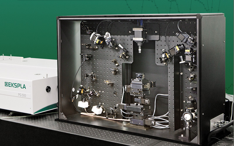
北京欧兰科技发展有限公司为您提供《聚合物支撑石墨烯中振动和频光谱检测方案(激光产品)》,该方案主要用于石墨烯中振动和频光谱检测,参考标准《暂无》,《聚合物支撑石墨烯中振动和频光谱检测方案(激光产品)》用到的仪器有PG400 系列皮秒光学参量发生/放大器系统、Ekspla SFG 表面和频光谱分析系统。
我要纠错
推荐专场
其它光谱仪
更多
相关方案
 咨询
咨询