方案详情文
智能文字提取功能测试中
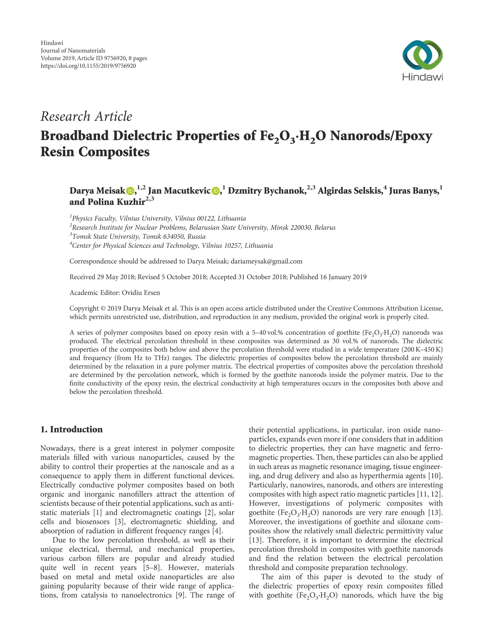
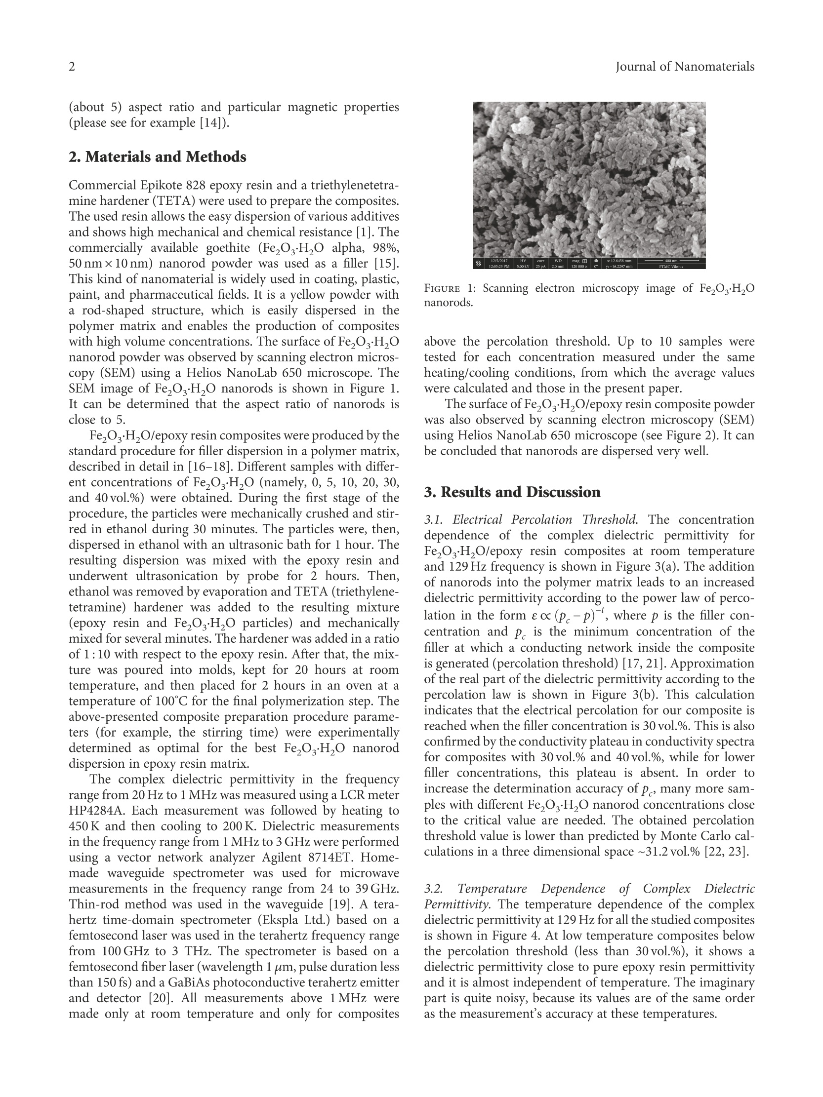
HindawiJournal of NanomaterialsVolume 2019, Article ID 9756920, 8 pageshttps://doi.org/10.1155/2019/9756920Hindawi 2Journal of Nanomaterials Research Article Broadband Dielectric Properties of Fe,O·H,0 Nanorods/EpoxyResin Composites Darya Meisak@,,Jan Macutkevic@, Dzmitry Bychanok,Algirdas Selskis, Juras Banys,and Polina Kuzhir23 Physics Faculty, Vilnius University, Vilnius 00122, Lithuania Research Institute for Nuclear Problems, Belarusian State University, Minsk 220030, Belarus Tomsk State University, Tomsk 634050, Russia "Center for Physical Sciences and Technology, Vilnius 10257, Lithuania Correspondence should be addressed to Darya Meisak; dariameysak@gmail.com Received 29 May 2018; Revised 5 October 2018; Accepted 31 October 2018;Published 16 January 2019 Academic Editor: Ovidiu Ersen Copyright @ 2019 Darya Meisak et al. This is an open access article distributed under the Creative Commons Attribution License,which permits unrestricted use, distribution, and reproduction in any medium, provided the original work is properly cited. A series of polymer composites based on epoxy resin with a 5-40 vol.% concentration of goethite (Fe0H,0) nanorods wasproduced. The electrical percolation threshold in these composites was determined as 30 vol.% of nanorods. The dielectricproperties of the composites both below and above the percolation threshold were studied in a wide temperature (200K-450 K)and frequency (from Hz to THz) ranges. The dielectric properties of composites below the percolation threshold are mainlydetermined by the relaxation in a pure polymer matrix. The electrical properties of composites above the percolation thresholdare determined by the percolation network, which is formed by the goethite nanorods inside the polymer matrix. Due to thefinite conductivity of the epoxy resin, the electrical conductivity at high temperatures occurs in the composites both above andbelow the percolation threshold. 1. Introduction Nowadays, there is a great interest in polymer compositematerials filled with various nanoparticles, caused by theability to control their properties at the nanoscale and as aconsequence to apply them in different functional devices.Electrically conductive polymer composites based on bothorganic and inorganic nanofillers attract the attention ofscientists because of their potential applications, such as anti-static materials [1] and electromagnetic coatings [2], solarcells and biosensors [3], electromagnetic shielding, andabsorption of radiation in different frequency ranges [4]. Due to the low percolation threshold, as well as theirunique electrical, thermal, and mechanical properties,various carbon fillers are popular and already studiedquite well in recentyyears [5-8]. However, materialsbased on metal and metal oxide nanoparticles are alsogaining popularity because of their wide range of applica-tions, from catalysis to nanoelectronics [9]. The range of their potential applications, in particular, iron oxide nano-particles, expands even more if one considers that in additionto dielectric properties, they can have magnetic and ferro-magnetic properties. Then, these particles can also be appliedin such areas as magnetic resonance imaging, tissue engineer-ing, and drug delivery and also as hyperthermia agents [10].Particularly, nanowires, nanorods, and others are interestingcomposites with high aspect ratio magnetic particles [11, 12].However, investigations of polymeric composites withgoethite (Fe,O.HO) nanorods are very rare enough[13].Moreover, the investigations of goethite and siloxane com-posites show the relatively small dielectric permittivity value[13].Therefore, it is important to determine the electricalpercolation threshold in composites with goethite nanorodsand find the relation between the electrical percolationthreshold and composite preparation technology. The aim of this paper is devoted to the study ofthe dielectric properties of epoxy resin composites filledwith goethite (FezO.H,O) nanorods, which have the big (about 5) aspect ratio and particular magnetic properties(please see for example [14]). 2. Materials and Methods Commercial Epikote 828 epoxy resin and a triethylenetetra-mine hardener (TETA) were used to prepare the composites.The used resin allows the easy dispersion of various additivesand shows high mechanical and chemical resistance [1].Thecommercially available goethite (Fe,O·H,O alpha, 98%,50 nm×10nm) nanorod powder was used as a filler [15].This kind of nanomaterial is widely used in coating, plastic,paint, and pharmaceutical fields. It is a yellow powder witha rod-shaped structure, which is easily dispersed in thepolymer matrix and enables the production of compositeswith high volume concentrations. The surface of Fe,O3.HOnanorod powder was observed by scanning electron micros-copy (SEM) using a Helios NanoLab 650 microscope. TheSEM image of Fe,O.H,O nanorods is shown in Figure 1.It can be determined that the aspect ratio of nanorods isclose to 5. Fe,O·H,O/epoxy resin composites were produced by thestandard procedure for filler dispersion in a polymer matrix,described in detail in [16-18]. Different samples with differ-ent concentrations of Fe,O,H,O (namely, 0, 5, 10,20, 30,and 40 vol.%) were obtained. During the first stage of theprocedure, the particles were mechanically crushed and stir-red in ethanol during 30 minutes. The particles were, then,dispersed in ethanol with an ultrasonic bath for 1 hour. Theresulting dispersion was mixed with the epoxy resin andunderwent ultrasonication by probe for 2 hours. Then,ethanol was removed by evaporation and TETA (triethylene-tetramine) hardener was added to the resulting mixture(epoxy resin and Fez03·H,O particles) and mechanicallymixed for several minutes. The hardener was added in a ratioof 1:10 with respect to the epoxy resin. After that, the mix-ture was poured into molds, kept for 20 hours at roomtemperature, and then placed for 2 hours in an oven at atemperature of 100℃ for the final polymerization step. Theabove-presented composite preparation procedure parame-ters (for example, the stirring time) were experimentallydetermined as optimal for the best Fe,O·H,O nanoroddispersion in epoxy resin matrix. The complex dielectric permittivity in the frequencyrange from 20 Hz to 1 MHz was measured using a LCR meterHP4284A. Each measurement was followed by heating to450 K and then cooling to 200 K. Dielectric measurementsin the frequency range from 1 MHz to 3 GHz were performedusing a vector network analyzer Agilent 8714ET. Home-made waveguide spectrometer was used for microwavemeasurements in the frequency range from 24 to 39 GHz.Thin-rod method was used in the waveguide [19]. A tera-hertz time-domain spectrometer (Ekspla Ltd.) based on afemtosecond laser was used in the terahertz frequency rangefrom 100 GHz to 3 THz. The spectrometer is based on afemtosecond fiber laser (wavelength 1 um, pulse duration lessthan 150 fs) and a GaBiAs photoconductive terahertz emitterand detector [20]. All measurements above 1MHz weremade only at room temperature and only for composites FIGURE 1: Scanning electron microscopy image of FezOs.H0nanorods. above the percolation threshold. Up to 10 samples weretested for each concentration measured under the sameheating/cooling conditions, from which the average values. were calculated and those in the present paper. The surface of Fe,O.HO/epoxy resin composite powderwas also observed by scanning electron microscopy (SEM)using Helios NanoLab 650 microscope (see Figure 2). It canbe concluded that nanorods are dispersed very well 3. Results and Discussion 3.1. Electrical Percolation Threshold. The concentrationdependence of the complex dielectric permittivity forFezO3.H,O/epoxy resin composites at room temperatureand 129 Hz frequency is shown in Figure 3(a). The additionof nanorods into the polymer matrix leads to an increaseddielectric permittivity according to the power law of perco-lation in the form ec(pc-p),where p is the filler con-centration and pe is the minimum concentration of thefiller at which a conducting network inside the compositeis generated (percolation threshold) [17, 21]. Approximationof the real part of the dielectric permittivity according to thepercolation law is shown in Figure 3(b). This calculationindicates that the electrical percolation for our composite isreached when the filler concentration is 30 vol.%. This is alsoconfirmed by the conductivity plateau in conductivity spectrafor composites with 30 vol.% and 40 vol.%, while for lowerfiller concentrations, this plateau is absent. In order toincrease the determination accuracy ofp, many more sam-ples with different Fe,O3·H,O nanorod concentrations closeto the critical value are needed. The obtained percolationthreshold value is lower than predicted by Monte Carlo cal-culations in a three dimensional space ~31.2 vol.% [22, 23]. 3.2 Temperature Dependence of Complex lDielectricPermittivity. The temperature dependence of the complexdielectric permittivity at 129 Hz for all the studied compositesis shown in Figure 4. At low temperature composites belowthe percolation threshold (less than 30vol.%), it shows adielectric permittivity close to pure epoxy resin permittivityand it is almost independent of temperature. The imaginarypart is quite noisy, because its values are of the same orderas the measurement's accuracy at these temperatures. (a) (b) FIGURE 2: Scanning electron microscopy image of FezO3H,O Nanorods/epoxy composites with 40 vol.% filler concentration (at differentmagnification levels). 15 16 (a) (b) FIGURE 3: (a) Dependence of the complex dielectric permittivity of Fe,O·H,O/epoxy on filler concentration at room temperature and 129 Hzfrequency. (b) A percolation law of the real part of permittivity eo(30-p)-0.24 for Fe,O·H O/epoxy composites. At high temperatures, the imaginary part of the dielectricpermittivity increases strongly even for composites below thepercolation threshold. Such behavior at high temperatures(above 400 K) is typical for epoxy resin composites [1] andis related to the phenomenon of electrical conductivity,which dominates in composites both above and below thepercolation threshold. The temperature dependence of thecomplex dielectric permittivity at different frequencies for a composite with 5vol.% filler concentration is shown inFigure 5. The imaginary part of the dielectric permittivitypresents a maximum, in which position is frequency-dependent. When the frequency increases, the maximumexpands and shifts towards higher temperatures. The real part of the dielectric permittivity decreases withincreasing frequency. Such dielectric dispersion is typical forepoxy molecule dynamics [1]. At high temperatures (above FIGURE 4: Temperature dependence of the complex dielectric permittivity of Fe,Os·H,O/epoxy composites at 129 Hz. FIGURE 5: Temperature dependence of the complex dielectric permittivity of Fe,03·HO/epoxy composites with 5 vol.% filler concentration atdifferent frequencies. FIGURE 6: Frequency dependence of the complex dielectric permittivity of Fe,O3H,O/epoxy composites with 5 vol.% filler concentration atdifferent temperatures. TABLE 1: Parameters of the Vogel-Fulcher law fit of the averagerelaxation time. Concentration (vol.%) ln {to,s} Eg/kg (K) To(K) 0 -27.4 2689 142 5 -20 1649 91 10 -18 773 152 20 -18 805 180 FIGURE 7: Temperature dependence of the average relaxation timeof Fe,03·H,O/epoxy composites. The solid lines correspond to theapproximations by Vogel-Fulcher law (see equation (1)) 3.3. Frequency DependenciesS0of Complex DielectricPermittivity. The frequency dependence of the complex dielec-tric permittivity at different temperatures for Fe,03·H,O/epoxy resin composite with 5vol.% filler concentration isshown in Figure 6. At temperatures above 25℃, the spectraof the imaginary part of the dielectric permittivity presentsa maximum corresponding to the absorption peak. Thephysical process that causes the absorption peak is thereorientation of the dipoles. This behavior is typical forcomposites below the percolation threshold, and it is due. to the dipole relaxation [18, 24]. 350K), the complex dielectric permittivity and the losstangent e le sharply increases due to the appearance ofelectrical conductivity. On cooling, the maximum of e" expands and shiftstowards low frequencies, while at low temperatures (below270 K), it generally disappears. The frequency at the maxi-mum of the imaginary part of the dielectric permittivity ata fixed temperature, Vmax, allow us to determine the average relaxation time by using the following equation: t=1/VmaxOn cooling, the relaxation time increases according to theVogel-Fulcher law (see Figure 7): where to is the relaxation time at very high tempera-tures, Eg is the activation energy, and To is the glasstransition temperature. Obtained parameters are presented in Tablee 1. Incomposites, the glass transition temperature increases withgoethite nanorod concentration. Thisincrease canbeexplained by the strong interactions between epoxy resinand (Fe,OsH,O) nanorods. Moreover, according to thetheoretical calculations, the density of composite could behigher than the pure polymer density, and therefore theincreasing of the glass transition temperature with the fillerconcentration could be observed [20]. The frequency dependence of the complex dielectricpermittivity in a wide frequency range at room temperatureis shown in Figure 8.The frequency range is wide (from hertzto terahertz). However, measurements above 1MHz wereperformed only for composites above the percolation thresh-old (30 and 40 vol.%). This choice was due to the fact that thepermittivity of composites below the percolation threshold atroom temperature is almost frequency-independent and itsvalue is close to pure epoxy resin permittivity [17, 20]. In microwave frequency range, the value of complex dielectricpermittivity is very similar to the corresponding propertiesof epoxy resin composites filled with iron nanowires andnanoparticles [11]. 3.4. Electrical Conductivity. The electrical conductivity o wascalculated according to the following equation: a=wee,where ω=2nv, v is the frequency, and e is the dielectricpermittivity of vacuum. The frequency dependence of theelectrical conductivity,a(v), for Fe,0·H O/epoxy resincomposite with 20 vol.% filler concentration at different tem-peratures (at temperatures not lower than 370K, where anyrelaxation related to the polymer matrix is observed indielectric spectra) is shown in Figure 9. In the investigatedfrequency range, two separate regions can be observedfor electrical conductivity, namely, the region of thefrequency-independent plateau (at low frequencies) and thefrequency-dependent region (at high frequencies) [24]: where apc is the DC conductivity and Aω’ is the AC conduc-tivity. The DC conductivity is due to a random distribution ofelectrical charge carriers. The AC conductivity o Ac increases,approximately, according to a power law with an almostequivalent slope. The conductivity spectra can be fittedwith equation (2) very well, except the data at very low Frequency (Hz) T(K)o370 ☆410▲390 m430 FIGURE 9: Frequency dependence of electrical conductivity ofFe,O·H,O/epoxy composites with 20 vol.% filler concentration atdifferent temperatures. The solid lines are the best fit according toequation (2). frequencies, where discrepancies appear due to blockingcontact effects [25].This behavior of both DC and ACconductivity can be addressed to the contribution ofelectronic conductivity inside epoxy resin [1]. A similarconductivity behavior was observed for all other investi-gated composites (see Figure 10) and has good agreementwith the data presented in the literature for metal oxidecomposites [10], as well as for composites based on, forexample, carbon filler [1, 16, 19, 26]. Another characteris-tic feature is an increase of the DC conductivity with thefiller concentration (see Figure 10). The temperature dependence of DC conductivity wasapproximated by the Arrhenius law: where ais the preexponential factor and E is the conduc-tivity activation energy.Obtained parameters are present inTable 2. In composites, the conductivity activation energy isalmost independent from filler concentration below thepercolation threshold, while above the percolation threshold,it decreases with filler concentration. Similar results areobtained for epoxy resin composites filled with carbonnanotubes and carbon black [1, 27]. Thus, at high temperatures, because of the finite conduc-tivity of the epoxy resin, electrical conductivity occurs incomposites both above and below the percolation threshold. 4. Conclusions The dielectric properties of Fe,OH,0 nanorods/epoxyresin composites are presented in a wide frequency rangefrom hertz to terahertz at temperatures of 200K-450 K. FIGURE 10: Temperature dependence of DC electrical conductivityof Fe,O3·H,O/epoxy composites with different filler concentrations. TABLE 2: Parameters of the Arrhenius law fit of the DC conductivity. (S/m) E /k,(K) . Pure resin 0.8·10° 13225 5vol.% 0.2·10* 10480 10 vol.% 0.8-10° 10073 20 vol.% 0.4.104 10438 30 vol.% 0.2.10° 9973 40 vol.% 0.3.10 .6921 The percolation threshold of Fe,Os·HO nanorods/epoxyresin composites was about 30 vol%. The dielectric propertiesof composites below the percolation threshold are mainlydetermined by relaxation in a pure polymer matrix. Thedielectric properties of composites above the percolationthreshold are determined by the percolation network, whichis formed by the filler particles inside the composite. At lowfrequencies, the DC conductivity is produce by the randomdistribution of electric charge carriers and increases withthe concentration of inclusions. At high temperatures,because of the finite conductivity of the epoxy resin, theelectrical conductivity occurs in the composites both aboveand below the percolation threshold. Data Availability The data used to support the findings of this study areavailable from the corresponding author upon request. Conflicts of Interest The authors declare that there is no conflict of interestregarding the publication of this paper. Acknowledgments This research was partly funded by H2020 RISE project734164 Graphene 3D. D. Bychanok and P. Kuzhir arethankful for the support by Tomsk State University Compet-itiveness Improvement Program. This research was alsopartially supported by the Research Council of Lithuaniaaccording to the Lithuanian-Belarus Collaboration ProgramProject (no. S-LB-17-2/LSS-120000-143). References ( [1] J.Macutkevic, P . Kuzhir, A. Paddubskaya et a l.,“Epoxy resin/ carbon black c o mposites be l ow the per c olation thr e shold,” Journal o f Nanoscience and N a notechnology, vol. 1 3 , n o . 8 , pp.5434-5439,2013. ) ( [2] J. Macutkevic, D. S eliuta, G. Valusis et al.,“High dielectricpermittivity of percolative composites based on o nion-likecarbon," Applied Ph ysics L e tters, vol. 9 5, no. 1 1 , a r ticle 112901,2009. ) ( [3] G. I nzelt, Conducting Polymers: a N e w Era in Electrochemistry, S pringer-Verlag, H eidelberg, 2008. ) ( [4] K. J. Vinoy and R. M. Jha, Radar Absorbing Materials: FromTheory t o D esign a nd C h aracterization, K luwer AcademicPublishers, Boston, 1996. ) ( [5] F. Qin and C . Brosseau, “A review and analysis of microwaveabsorption i n p olymer c o mposites filled w ith c arbonaceous p articles,”Journal of Applied Phy s ics, vol . 111 , n o . 6 , a r ti c le 061301 , 2012. ) ( [6] M. Fu, Y. Y u , J. J. X ie e t al.,“Significant i nfluence o f f i lmthickness on t he p ercolation threshold of multiwall carbonnanotube/low density p olyethylene composite f ilms, "A pplied Physics Letters, vol. 94, no. 1 , artic l e 012904 , 2009. ) ( [7] K. Ahmad, W. Pa n , an d S.-L. Shi, “Electrical conductivity and dielectric propertie s of multiwalled carbon n anotube a n d a lumina composites," Applied Phy s ics Letters, vol . 89, no. 13, article 133122, 2 006. ) ( [8] W . B a uhofer and J. Z. Kovacs, “A re v iew and analysis of elec-trical percolatio n in carbo n nanotube polymer composites, Composites Science a nd Technology, vol. 69, no. 10, pp. 1486-1498,2009. ) ( [9] G. Y . Yurkov, S. P. G ubin, D . A . P a nkratov et al.,“Iron (III)oxide n anoparticles in a polyethylene ma t rix,” Inorganic M aterials, v ol. 38, no. 2, pp. 137-145,2002. ) ( [10] E. T emizel, E . A yan, M. Senel et a l ., “Synthesis, c onductiv- ity and magnetic p roperties of poly(N-pyrrole phosphonicacid)-Fe04 4 n anocomposite,” Materials C hemistry ang Physics, vol . 131 , no. 1-2, pp. 284-291, 2011. ) ( [11] R . B . Y ang, W. F. L i ang, W. S. Lin, H. M. Lin, C. Y. Ts a y, and C. K. Lin,“Microwave absorbing properties of iron nanowire at x-band f r equencies,” Journal of Applied Physics, vol. 109, no. 7, article 07B527,2011. ) ( [12] M. K rajewski, W . S. Lin, H . M. L i n et a l ., “Structural andmagnetic properties of iron nanowires a nd iron n anoparticlesfabricated t hrough a reduction reaction," Bei l stein Jo u rnal of Nanotechnology, vol. 6, pp . 1652-1660,2015. ) ( [13] M . Iacob,G. Stiubianu, C. Tugui et al. , “Goethite nanorods as a cheap and effective filler for siloxane nanocomposite elasto-mers,"RSC Advances, vol. 5, no. 56, pp. 45439-45445, 2015. ) ( [ 1 4] R . Marino-Fernandez, S. H . Masunaga, N. Fontaifa-T r oitino, M. P. Morales, J. Rivas, and 1\ V . Salgueirino, )、 “ Goethite ) ( FeOOH) nanorods as suitable antiferromagnetic sub- strates,” The Journal of Physical Chemistry C, v o l.11 5 , no. 29,pp. 13991-13999,2011. ) ( [15] h ttps://www. u s-nano.com/inc/sdetail/42381. ) ( [ 16] D.B y chanok,G. Gorokhov, D. Meisak et al.,“Design of carbon nanotube-based broadband r adar absorber f or K a-band f requency r ange,”Progress In Electromagnetics R esearch M , vol. 53, pp. 9-16, 2 017. ) ( [17] D. Bychanok, P. Kuzhir, S . M a ksimenko, S. B el l ucci, an d C. B rosseau, “ Characterizing epoxy composites filled w ith carbonaceous n anoparticles from dc to microwave,”Journal of Applied Physics, vol. 1 1 3 , no. 12 , article 124103, 201 3 . ) ( [ 18] S. B ellucci,L. C oderoni, F. Micciulla, G . R i naldi, and I. Sacco, “The e l ectrical properties o f epoxy resin co m posites fill e d with Cnts a nd carbon b l ack,”Journal of Nanoscience andNanotechnology, vol. 11, no. 1 0, pp. 91 1 0-9117, 2 011 . ) ( [ 1 9] J . Grigas, Microwave D i electric Spectroscopy ofFerroelectrics and R elated Materials, Gordon a nd B r each P u blishers,Amsterdam, 1 996. ) ( [20] I . Kranauskaite, J. M acutkevic, J. Banys et al., “Synergy effects i n t he e lectrical conductivity behavior of onion-like carbonand m ultiwalled c arbon n anotubes composites,” P h ysica S tatus Solidi (B), vol. 252, n o. 8 , pp.1799-1803, 201 5 . ) ( [ 21] D. v an der Putten,J. T. Moonen, H . B. Brom,J. C. M. Brokken-Zijp, and M . A. J. Michels,“Evidence for s u perlocalization on afractal network in conductiv e carbon-black-polymer compos- ites,” Physical Review Letters, vol. 69, no. 3, pp. 494-497, 1992. ) ( [22] S .Kirkpatrick, "Percolation phenomena in higher dimensions: approach t o the m e an-field l i mit,”P h ysical Review Letters,vol. 36, no. 2, pp.69-72, 1 976. ) ( [23] Y. Deng and H. W. J. Bl o te, “Monte Carlo study of the s ite-percolation model i n t wo and t h ree d i mensions,” P h ysical Review E , v o l. 72, no. 1, article 0 1 6126, 2 005. ) ( [24] A. K. J o nscher,“N e w inte r pretation of dielectric loss peaks,”Nature, vol. 256, no . 5518, pp.566-568, 1 975. ) ( [25] J. Banys, J. Macutkevic, V. Samulionis, A . B r ilingas, a nd Y . V y s ochanskii,“Dielectric a n d ul t rasonic investigation o f phase t r ansition i n c uinp,s, crystals,” P hase Transitions,vol. 77, no. 4, p p . 345-358 , 2004. ) ( [ 26] H . M . Kim, M. S. Choi, J. J o o, S. J . Cho, a nd H. S . Yoon,“Complexity i n c harge t ransport for m ultiwalled carbon n anotube a n d poly(methyl me t hacrylate) co m posites," Physi- c al R eview B , vol. 74, n o. 5, a rticle 054202, 2 006. ) ( [ 27] J. M acutkevic, P. P. K uzhir, A. G. Paddubskaya et al., “ Broad-band d i electric/electric p roperties o f e p oxy thin fil m s filledwith m ultiwalled carbon nanotubes,” J ournal of Nanopho- tonics, vol. 7 , no . 1, article 073593,2013. ) Nanomaterials The ScientificWorld Journal Journal of Scientifica vm International Journal ofPolymer SciencelJirJils Advances in Physical Chemistry Hindawi Submit your manuscripts at www.hindawi.com International Journal ofAnalvtical Chemistry Advances in Condensed Matter Physics Journal of Nanotechnology ..... BioMed Advances in Advances It Research International Tribology Materias srience and Engineering m2M A series of polymer composites based on epoxy resin with a 5–40 vol.% concentration of goethite (Fe2O3·H2O) nanorods was produced. The electrical percolation threshold in these composites was determined as 30 vol.% of nanorods. The dielectric properties of the composites both below and above the percolation threshold were studied in a wide temperature (200K–450 K) and frequency (from Hz to THz) ranges. The dielectric properties of composites below the percolation threshold are mainly determined by the relaxation in a pure polymer matrix. The electrical properties of composites above the percolation thresholdare determined by the percolation network, which is formed by the goethite nanorods inside the polymer matrix. Due to the finite conductivity of the epoxy resin, the electrical conductivity at high temperatures occurs in the composites both above and below the percolation threshold.
关闭-
1/9
-
2/9
还剩7页未读,是否继续阅读?
继续免费阅读全文产品配置单
北京欧兰科技发展有限公司为您提供《Fe2O3·H2O纳米棒/环氧树脂复合材料中太赫兹光谱检测方案(其它光谱仪)》,该方案主要用于环氧树脂中可靠性能检测,参考标准《暂无》,《Fe2O3·H2O纳米棒/环氧树脂复合材料中太赫兹光谱检测方案(其它光谱仪)》用到的仪器有Ekspla T-SPEC 实时太赫兹(THz)光谱仪。
我要纠错