

方案详情文
智能文字提取功能测试中
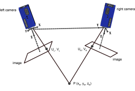
Additive Manufacturing 25 (2019) 19-31Contents lists available at ScienceDirectAdditive Manufacturing Additive Manufacturing 25 (2019)19-31B. Mooney et al journal homepage: www.elsevier.com/locate/addma Plastic anisotropy of additively manufactured maraging steel: Influence ofthe build orientation and heat treatments Barry Mooney, Kyriakos I. Kourousis ,*, Ramesh Raghavendra" School of Engineering, University of Limerick, V94 T9PX, Ireland'South Eastern Applied Materials Research Centre (SEAM), Waterford Institute of Technology, X91 TX03, Ireland ARTICLEINFO ABSTRACT Keywords:Additive manufacturing3D printingMaraging steelAnisotropyHeat treatmentStrength Ductility This experimental study investigates the combined effect of the three primary Additive Manufacturing (AM)build orientations (0°, 45°, and 90°) and an extensive array of heat treatment plans on the plastic anisotropy ofmaraging steel 300 (MS1) fabricated on the EOSINT M280 Direct Metal Laser Sintering (DMLS) system. Thealloy's microstructure, hardness, tensile properties and plastic strain behaviour have been examined for variousstrengthening heat-treatment plans to assess the influence of the time and temperature combinations on plasticanisotropy and mechanical properties (e.g. strength, ductility). A comprehensive visual representation of thematerial's overall mechanical properties, for all three AM build orientations, against the various heat treatmentplans is offered through time-temperature contour maps. Considerable plastic anisotropy has been confirmed inthe as-built condition, which can be reduced by aging heat-treatment, as verified in this study. However, it hasidentified that a degree of transverse strain anisotropy is likely to remain due to the AM alloy's fabricationhistory, a finding that has not been previously reported in the literature. Moreover, the heat treatment plan (6hat 490℃) recommended by the DMLS system manufacturer has been found not to be the optimal in terms ofachieving high strength, hardness, ductility and low anisotropy for the MS1 material. With the use of thecomprehensive experimental data collected and analysed in this study, and presented in the constructed contourmaps, the alloy's heat treatment parameters (time, temperature) can be tailored to meet the desired strength/ductility/anisotropy design requirements, either for research or part production purposes. 1. Introduction Structure-critical metallic components, produced by additive man-ufacturing (AM), are expected to display a high degree of isotropy.Thedependence of mechanical properties on orientation, known as aniso-tropy, is a consequence of the metal's fabrication history which placeslimitations on the design of the part. Maraging steels possess the me-chanical properties which give them engineering significance in appli-cations where high-strength, toughness and ductility (at high-hard-ness), and dimensional stability are required [1-3]. Based on the binaryFe-Ni primary phase system, the highly-alloyed steel is strengthened byfinely dispersed precipitates, which block movement of dislocations/defects within the crystal lattice. The dispersion of secondary phasealloying elements (Mo, Co, Ti and Al), mobilized through a straight-forward and relatively expeditious aging heat-treatment, leads to anexceptional combination of strength and toughness [4-6,2]. Maraging steel's low-carbon soft martensitic matrix is mostly free from interstitialalloying elements, which rank it as an excellent candidate for synthesisby AM and welding [1,6-8]. The 18Ni (300) grade, or slight mod-ifications thereof, has been used in AM, and is retailed commercially inpowder form under several aliases. The quality assured MS1 is one suchpowder supplied by EOS[10]. This powder has been suitably refined forEOS's powder-bed AM systems and processing techniques, which haveretained the historical proprietary name Direct Metal Laser Sintering(DMLS). Another, commonly used, term for this process is SelectiveLaser Melting (SLM), since the technique employs a high-powered laser-beam energy source to fully melt powder particles into a high density,and chemically homogeneous composition. Driven by computer aideddesign (CAD) data, the laser's scanning strategies can be used to achievelayer-wise growth of imaginative, and relatively unconstrained geo-metries [11,10]. It is thiee aa.lloy's outstandingg properties anddheat-treatment ( * Corresponding author. ) ( Available online 31 October 2018 ) expediency in conjunction with the AM process's shaping efficiency thatgive DMLS produced maraging steel 300 such appeal. These factorsallow for a much-accelerated fabrication route than conventionallymanufactured (CM) parts, and thus offsets the high acquisition cost ofthe alloy, as well as the process costs. DMLS built maraging steel 300,however, has a major drawback amongst its CM counterpart. The me-chanical properties are known to be anisotropic due to an inherentsensitivity with regards to how a part is orientated within the AM buildvolume [11-13]. This anisotropy is manifested through the fabricationprocess where large thermal gradients during melt-pool solidification,combined with the layer-wise deposition of the powder, planar move-ment of the heat source, and uniaxial movement of the build-plate,make it difficult to homogenize the microstructure and mechanicalproperties of the as-built metal. A mesostructure of fine solidificationcells, unique to the powder processing method and consequent to thepowder granule melt dynamics, is coupled with continuous re-melting/heating of material beneath the melt-pool during build-up causes adistinct three-dimensional (3D) microstructural pattern to form. Thisresults in mechanical properties which vary with direction and causesthe material to exhibit anisotropic mechanical properties. Furthermore,the state of anisotropy can be exacerbated by ancillary process defects,such as residual stresses, and porosity, and a number researchers haveinvestigated the effect of AM processing parameters to improve thebuild quality of maraging steel 300 [14-16]. As indicated by EOS in the MS1 material data sheet (MDS) [11], thematerial becomes isotropic following application of a specified agingheat-treatment (6h at 490℃), however, the MDS is not sufficient tocharacterize the material performance for engineering designs andproducts, since it covers only the primary build orientations (0°,90°),and comes from a single source (EOS). The effectiveness of both the AMfabrication and heat-treatment procedure can only be measured by theextent to which the as-built and treated component behaves undermechanical loading, yet very limited published research [17,18] existsconcerning the build orientation influence on mechanical behaviour ofAM-produced maraging steel 300.[18], who investigated the depen-dence of build orientation relative to the build plane (0°,45°, and 90)on the high-cycle fatigue life of EOS M280 produced MS1 specimens inthe aged (6h at 490℃) condition only, found no substantial differenceon the fatigue properties. Recently, [17] examined the tensile proper-ties of EOS MS1 fabricated at 0°, 45°, and 90°, and contrary to the EOSpublished MDS [11] they observed no significant orientation depen-dence in the tensile stress-strain behaviour for as-built, solution heat-treated (1 h at 820°C), and aged (6h at 490°C) material. Other avail-able test-data is mainly limited to static testing (tensile, and/or hard-ness) of maraging steel 300 fabricated in One[19,14,7,20,6,21,22,3,23,24],or two [25,26,12,16,27] of the primaryAM build orientations. The most comprehensive of these studies interms of the reported mechanical properties is [7], which monitors theeffect of an array of aging heat-treatments on the static properties ofAM fabricated maraging steel 300. While the study presents a broadrange of hardness results, only very limited tensile properties are re-ported (i.e. for the as-built and five other peak-aged heat-treatmentconditions). Furthermore, only the horizontal (0°) build-orientation isconsidered. Authors [28,29] and [16] also present hardness and tensiledata for horizontal specimens tested under a narrow array of agingtreatments. In these studies, however, non-characteristic fluctuations/variations in the AM alloy's elasticity and plasticity behaviour can be observed. While explanations for these abnormalities are not asserted,they may indeed be introduced during the fabrication process and/orduring the material characterization process (e.g. due to the tensile testrates employed). Nevertheless, these irregularities mandate a morecomprehensive and detailed experimental analysis of AM maragingsteel 300 monotonic behaviour. So far, the effect of aging heat-treat-ment on stress and strain anisotropy for this particular material has notbeen previously addressed, and there have been no reported findings onstrain anisotropy for parts fabricated at various build orientations (i.e.0°, 45°, and 90°). Moreover, the availability of tensile properties for AMfabricated maraging steel 300 for the primary build orientations (0°,and 90°) is limited. Other significant work has been performed to-datein characterizing the microstructure [23,30,31,29,27,32], precipitationreactions [33,6], and austenite reversion behaviours [34,21,7,30] withseveral of these studies reporting similar microstructures in maragingsteel 300 having been produced on a range of AM machines undervarying process parameters. Since it is necessary to consider the material's multiaxial mechanicalproperties during the process of mechanical component design, the lackof orientation dependence data presents challenges for engineers whenit comes to utilising the highly advantageous AM technology for theirengineering designs and products. In order to address the aforemen-tioned research literature gaps, in this work, we report a comprehensiveexperimental analysis of maraging steel 300 mechanical properties andplastic anisotropy behaviour. In doing so, we take into account both theeffect of three AM build-orientations (0°,45°, and 90°), as well as a largearray of heat-treatment plans (combinations of time, and temperature)to allow for a wide-scale investigation of anisotropic variation, notpreviously conducted in the past for this AM material. Plastic aniso-tropy describes an uneven response of the alloy's plastic properties (orflow-strain relationships) with respect to the AM build orientations, andhas been quantified in this investigation by the R-value parameter. R-value is the ratio of true width-to-thickness plastic strains, and thisparameters allows an examination of the alloy's tendency to strain non-uniformly by consequence of the test-coupon's build-orientation. Thefull mapping of AM fabricated maraging steel 300 mechanical proper-ties for all three build orientations, in conjunction with their respectiveR-values has not previously been reported in the literature, and canserve as a very practical tool for AM engineers and researches wishingto tailor the output of the EOS MS1. This novel experimental work isparticularly focused on providing a means of AM maraging steel 300heat-treatment selection to meet individual strength/ ductility/ aniso-tropy engineering design requirements, and intends to act as a guideproject for other AM manufactured metals exhibiting anisotropy. 2. Material and methods 2.1. Material and AM process Gas-atomized MS1 powder feedstock supplied by EOS was used. Thechemical composition of the raw-material is shown in Table 1, whichcorresponds to US classification 18 Maraging (300), German X3NiCo-MoTi 18-9-5, and European 1.2709 [35]. In the same table, the resultsof the energy dispersive x-ray (EDX) analysis, conducted with a HitachiSU 70 Scanning Electron Microscope (SEM), for the main comprisingelements are also presented. The powder presented spherical particlestypically measuring under 50 um. The SEM morphology and particle Chemical composition (%wt) of MS1, the 18Ni (300) grade maraging steel powder supplied by EOS [11] with SEM-EDX analysis results for the main comprisingelements (EDX sampling area:≈10um). Ni Mo Co Ti Al Cr Si Mn C Fe MS1 [11] 17-19 4.5-5.2 8.5-9.5 0.6-0.8 0.05-0.15 0-0.5 0-0.1 0-0.1 0-0.03 Bal. SEM-EDX 18.14 5.67 8.94 0.87 Bal. (a) size distribution, analysed using a Malvern Morphologi G3 particleanalyser, are shown in Fig.1(a) and (b) respectfully. The observedmedian particle size was 36.69 um, and had a standard deviation (SD)of 10.74 um. The median particle circularity (deviation from a perfectcircle, where perfect circularity = 1) was 0.956. A rectangular-shaped tensile test specimen, meeting the require-ments of the ASTM E8M standard [36], was selected to allow for bothlateral and axial elastic and plastic strain measurements whilst undertensile loading. The test specimen geometry, dimensions and tolerancesare shown in Fig. 2(a). Test-specimens having a uniform cross-section atgage, were fabricated at SEAM, IE using the EOS EOSINT M280 systemwithin an atmosphere of inert Nitrogen over the course of three con-secutive AM builds. The M280 was equipped with 200W Ytterbium-fibre laser and was fitted with the manufacturers recommended (forMS1) ceramic re-coater blade. To investigate the influence of buildorientation on property anisotropy, test-specimens were fabricated inthe Y-Z build plane at three angles (0°(horizontal), 45°(inclined), and90°(vertical)) between their longitudinal axis and the build platform, asshown in Fig. 2(b). A total of forty-eight (48) samples were fabricated(i.e. sixteen (16) test-pieces for each AM orientation) from a virginbatch of MS1 feedstock over three consecutive AM builds. As shown in Fig. 3, the AM build leaves visible ridges upon parts’build surfaces and a stair-stepped effect on 45°sloping surfaces whichare indicative of the layered fabrication process. High roughness at thesurface can augment crack initiation thus leading to pre-mature failure.Furthermore, these ridges hinder the accurate evaluation of gage widthand thickness dimensions. Ductility calculations are sensitive to themeasurement of gage cross-sectional area, while the ASTM E8M stan-dard exhorts that particular attention be given to the uniformity andquality of surface-finish with regards high-strength specimens [36]. Forthese reasons, an additional 0.5 mm of machinable material was added to each face prior to the AM-build. This surplus material, which waslater machined by single-cycle precision computer numerically con-trolled (CNC) wire electrical discharge machining (EDM) profiling andsurface-grinding operations, had the extra benefit of safeguardingagainst potential thermally induced distortion. The EOS M280 machine's hardware was driven by the factory de-fault, undisclosed, andpre-optimized set of parametersMS1Performance 2.0'which has been developed by the manufacturer for thisspecific material and machine combination [35]. EOS claims that theirset of parameters (MS1 Performance 2.0) ensures reliable mechanicalproperties. This offers a defined part property profile bolstering in-dustry-level repeatability and quality [37]. A vertical support-scaffoldconnected the under-side of each specimen to the manufacturer’s re-commended building platform (Steel 1.2083 36mm thick DirectBaseTS36P) [35]. This structure played two important roles during theelevated temperature production cycle-(a) it functioned as a passiveheat-sink during manufacturing; and (b) it reinforced the 45° inclinedspecimens against cross-platform re-coater forces and earthward grav-itational forces. As verified by the post-build inspection, the process hadachieved sound metallurgical bonding between layers, with a uniformand characteristic ridged surface. The parts were dimensionally accu-rate, however it is worth noting that a longitudinal shrinkage distortion(bowing) in the AM build direction (Z), to the extent of ≤ 0.1 mm, wasobserved in several horizontal (0°) specimens after their removal fromthe build-plate. This shrinkage, which was rectified in the downstreammachining operation, is understood to have been brought about by abuild-up of thermal stresses developed between the raw-material andbase-plate metal during the heating and cooling cycles over the openingnumber of layers. The heat treatment (aging) was performed in a pre-heated EliteThermal Systems 120 litre 6kW heavy duty-fan oven (air atmosphere) Fig. 3. DMLS fabricated samples of the 45° build orientation before detachment of the support scaffold from the parts/build-platform. Detail A highlights thepresence of distinct surface ridges which are consequent to the layer-wise fabrication process. Table 2 Showing the experimental heat-treatments applied to full-sets of test-specimens(i.e. 0°, 45°, 90°), where the characters T’and 'H’symbolize a tensile, and/orVickers Hardness test-campaign. Temperature Aging time [hours,h] [C] 1h 2h 3h 4h 5h 6h 8h 10h 12h 15h 16h 460°C - - - H T,H T,H T,H - H 490C H - H T,H - H - - 525°C - H T,H H T,H T,H H - H - 540°C H T,H H T,H T,H H - - 600°C T,HT,HI H T,H H T,H H - - - controlled by dual Eurotherm 3216 PID temperature controllers andcooled slowly in still air at ambient temperature (23℃). The experi-mental heat-treatment plan is shown in Table 2, where T denotes tensiletests and H the Vickers hardness measurements performed for a set of0°,45°, 90°specimens. The treatment temperature dictates the kinetics of phase separationin the alloy's matrix, and ultimately determines the population and sizeof precipitates which form, thus, aging temperature has the most sig-nificant effect on precipitate size and dispersion in maraging steels[38]. The EOS recommended heat-treatment temperature of 490°℃ al-lows a populous dispersion of hindering precipitates to form over thestated 6h aging period. It is the interaction between dislocations andprecipitates which determines the material's strength and ductility.Prolonged holding at temperatures below austenite start (As~560℃)not only reduces the effectiveness of dislocation hindrance but willeventually lead to a decomposition of martensite by diffusion-con-trolled reactions to a stable blend of austenite and ferrite. Aging attemperatures approaching As reduces the population of developingprecipitate particles and heightens the propensity for austenite rever-sion where its formation can even precede precipitation. Higher agingtemperatures are employed when good toughness/ductility is sought,and to that end-the EOS M280 parameter sheet [39] outlines an agingtreatment of 6 h at 525℃(-600℃). The experimental heat-treatments(Table 2) were therefore selected to confirm EOS recommendations; toformulate a comprehensive evaluation of static mechanical properties;and to allow for wide-scale investigation of the anisotropy variation. 2.2. Characterization A Taylor Hobson Hommel Tester T500 surface profiler was used tomeasure the roughness variation due to surface orientation within the build volume. For each build orientation, the profiler's stylus was tracedalong specimens’ loading axis using an assessment length of 4.8 mm.Two roughness parameters were utilised: · Rz representing the mean roughness depth by calculating theaverage value of the five highest peaks and five deepest valleys overthe assessment length; Ra corresponding to the arithmetical mean surface roughness valueof all profile deviations over the assessment length. Archimedes’ Principle density measurements, in compliance withASTM B962-17 [40], were performed using a Sartorius Quintix labora-tory balance (model 65-1S) equipped with accessory YDK03 densitydetermination kit. Uniaxial tensile tests were conducted at ambient temperature in acalibrated Zwick/Roell (Dartec) M1000/RK servo-hydraulic closed-looptesting machine equipped with 100 kN capacity load cell and fittedwith ±100kN fatigue rated hydraulic wedge grips. The test routinefollowed strict adherence to the guidelines present in ASTM E8M [36].The test was initially controlled (via 9600 series controller) to theelastic stressing rate of 10.34MPa/s, using strain control from the ex-tension feedback channel (Epsilon model 3542-025M-050-ST). Upondetection of yield, the test-rate maintained a constant plastic strain rateof 6.25 ×10⁻⁴/s controlled via the stroke feedback channel. At the endof the yield (detected from either reaching a 5% increase in stress, or anabsolute strain limit of 2%), the test-velocity was commanded by a thirdrate, the tensile strength (Rm) rate: 0.0068/s. This strain rate wasmaintained to peak force, and through to failure. Non-contact full-field strain and deformation was measured andanalysed using La Vision's portable 3D Digital Image Correlation (DIC)apparatus. The apparatus comprised of (i) two 12-bit Imager E-lite CCD-chipped cameras fitted with 35 mm lenses, (ii) two gated white lightsources each containing twelve linear-configured LEDs,,((iii)aStrainMaster Controller and data-acquisition unit with integrated ana-logue-to-digital converter (A/D), and (iv) a dedicated PC complete withStrainMaster@ processing software. The experimental arrangement isshown in Fig. 4. Each camera was focussed onto the measurement planeproviding an overlap region upon the specimen gage surface. The en-closed angle between cameras and the working distance between eachcamera and the test-specimen was ≈20°and≈350mm respectively.Using the stereoscopic camera system's in-situ position, a global 3D-coordinate system was derived by means of a precursory calibrationstep involving a 3D two-level calibration target/plate. This included thegeneration of a fit mapping function with the calibration plate from Fig. 4. Configuration of tensile test set-up including the 3D Digital Image Correlation (DIC) apparatus which allowed concurrent determination of test-specimenwidth and axial strains (Ew and e). which the average deviation of the dewarped calibration target posi-tions to the ideal positions was lower than 0.3 pixel. This corresponds toan excellent fit, and an appropriate basis for the proceeding full-field 3Dstrain-measurement evaluations [41]. A high-contrast acrylic paint dark'speckle’pattern (dark black speckles on a bright white background)was applied to the area of interest (i.e. the specimens’gage surface).Special attention was given to achieving a relatively fine pattern scale(for higher spatial resolution) with a non-repeating isotropic distribu-tion. In this study, each subset (or“window") had an area of 37 pixels,which translated to approx. 1.75 mm. The goal of the speckle is toprovide each subset with a unique signature pixel arrangement fromwhich the displacement pattern can be tracked in 3D space with micronaccuracy by the StrainMaster software's pattern matching algorithm[42]. A sequence of images was captured during each tensile test (i.e.from zero applied load to fracture) at a periodic rate of 5 Hz. A dis-placement vector corresponding to each subset was calculated by theStrainMaster least squares matching algorithm from a reference (un-deformed) image. The basic result of the DIC analysis was a full-field 3Ddisplacement measurement evaluation containing thousands of mea-surement points. In accordance with ASTM test methods E132-04 andE517-18 [43,44], Poisson (v) and plastic strain ratios (R-values) havebeen evaluated using DIC data. In turn, the individual test-specimen R-values (Ro, R45, and R90), are unified by the parameter AR which is usedto quantify planar anisotropy (i.e. in the AM Y-Z plane) by Eq. (1). Metallographic samples were sectioned and mounted with BuehlerLtd. PhenoCure compression mounting compound, and standard fin-ishing steps applied -including polishing with oil based monocrystal-line diamond suspension (6um and 1 um), MetaDi from Buehler Ltd..Modified Fry's reagent was used to reveal the microstructure which wasobserved via an Olympus BX60 Optical light microscope, and Hitachi SU70 Scanning Electron Microscope equipped with an Oxford InstrumentsEDX attachment for analysis of the comprising chemical elements. The progress of the aging heat-treatment was evaluated using acalibrated Zwick ZHV Vickers macro-hardness tester and verified with astandard test block to the requirements of ASTM E92-92 [45]. Samples were sectioned, mounted, and polished, then subjected to a 30 kg testforce which was applied parallel to the AM material's tensile loadingaxis (i.e. perpendicular to the sectioned plane). At least 20 hardnessmeasurements were performed on each test specimen, and the resultsand test statistics were computed using the R statistical softwarepackage [46]. The material's crystal structures were qualitatively analysed (forselective heat-treatments) via a PANalytical Empyrean Pro multipurposeX-ray diffractometer (XRD) using Cu Ka radiation. Crystallographicphase identification was achieved using HighScore Plus software. 3. Results and discussion 3.1. Surface roughness and density analysis The as-built and machined surface roughness, along with density (p)measurements, are presented in Table 3. The EOS quoted density of8.0-8.1 g/cm, and roughness parameters for as-built horizontal up-facing or vertical (90°) surfaces produced with 40 um layer-thickness(Rz = 28 um and Ra=5 um) are in general agreement with the pre-sented results. The measurements imply that part density is not influ-enced by AM build orientation. Regarding chemical composition-therewas close agreement between SEM-EDX and the published values [11]for MS1 as shown in Table 1. Table 3 Axial surface roughness and density measurements (ASTM B962) for the as-built Horizontal (0°), Inclined (45°), and Vertical (90°) MS1 specimens. 0)° 45 90 Machined Rz (um) 29.21 16.17 21.69 0.47 Ra (um) 6.63 3.04 4.2 0.09 p(g/cm) 8.051 8.050 8.049 NA Build Fig. 5. Schematic representation of the DMLS laser scan strategy which has been inferred from microstructural observations. Each layer’s uni-directional line-scanwas divided into short stripes of length 0.3-0.6 mm to prevent excessive localized heating. 3.2. As-built microstructure A schematic representation of the laser scan strategy pertaining tothe manufacturer's recommended set of parameters (MS1 Performance2.0) is shown in Fig.5. This set of parameters prescribed uni-directionline-scans with a laser hatch-spacing of 110 um. The hatch-spacing andline-scan direction remained constant within each AM layer where eachline-scan was segmented into stripe divisions of approximately0.3-0.6 mm, presumably to prevent excessive localized heat build-upduring fabrication. The scan-direction was rotated by 67° for eachconsecutive 40um-thick layer in an effort to homogenize the micro-structure. The outcome is a practically fully dense part, with stronginter-layer and intra-layer metallic bonding. No significant processdefects in the form of porosity or un-melted powder particles wereobserved in the microstructures. It is understood that the absence ofdefects is largely due to the powder characteristics, since an abundanceof small spherical granules in the virgin feedstock augmented flow-ability and allowed maximum space occupancy during re-coating uponpreviously distributed layers. Fig. 6 presents optical macrographs, and as-built SEM micrographsfor each build-orientation. The AM characteristic laser melt tracks areapparent at low magnification in Fig. 6(a),(b), and (c). The typical as-built horizontal maraging steel 300 macrostructure (Fig. 6(a)) has acomplect appearance, with bundled interconnections of fan-shapedsolidification cells between molten lines. The moderately sized melt-pool widths (45-70 um), and depths (35-55 um) are reflective of theapplied laser energy input (<200 W). The observed melt-pool width isindicative of a laser focus diameter of ~ 60um, while the measuredmelt-pool depth is typical for this powder layer-thickness (40 um).Larger laser focus-diameters (100 um) have been used with higher ca-pacity AM platforms (laser power: 285W) administering equivalentlayer-thickness [30]. By contrast to the horizontal cross-section, the 67°rotation of laser scan angle (between the sectioned and precedinglayers) is clear on the vertical cross-section (Fig. 6(c)). As observed in the high-magnification SEM images (Fig. 6(d), (e),and (f)), the AM laser scanning algorithm gives rise to various cellularmorphologies including fine, coarse, and dendrite cell formations(highlighted on the images by dotted lines). The evolution mechanismsof these growth formations relate to the melt-region thermal flux di-rection which changes for successive layers and is theoretically ex-plained in a recent study by Tan et al. [30]. Assisted by rapid coolingrates (circa 10° to 10° K.s-), these very fine cellular formations orientate themselves concurrent with the direction of heat flow/re-moval [29,27,26,33,23,34]. Interestingly, other research [27,47] hasfailed to identify any dominant crystallographic or fibre texture with apreferred grain growth orientation from the AM processed alloy. Thissuggests that maraging steel 300 may be less susceptible to texture-generated anisotropy than other AM fabricated materials (see[48-51])which exhibit strong crystallographic preferred orientation. The SEMobserved cellular morphology is believed to be a major contributor tothe strength difference between AM as-built versus the solution-an-nealed conventionally produced alloy, which in-contrast does not dis-play retained austenite in its microstructure, and exhibits randomparent grains, each containing coarse and disordered packets of parallellath-martensite [3,6,52,34,16]. Retained austenite is easily distin-guishable in the high magnification images (Fig. 6(d), (e), and (f)) asthe bright-colour phase which aggregates at cell boundaries. It occurswhen the material cools rapidly from austenite finish (A) to ambienttemperature, essentially freezing in place solute-rich austenite leaving ituntransformed, whereas solute depleted austenite transforms intomartensite. Accordingly, the importance of appropriate processingvariables is evident since these will govern the volume of retainedaustenite in microstructure, and ultimately the part performance. To-date, however, no studies have quantified the effect of as-built (re-tained) austenite on the post-heat-treated mechanical properties of AM-fabricated maraging steel 300. 3.3. Aged microstructure Micrographs of the aged alloy, and their corresponding XRD spectraare presented in Figs. 7, and 8 , to demonstrate the effect of agingtemperature on the reversion of metastable bcc martensite phase (Fe-a)to fcc austenite (Fe-y). The reversion occurs during extended isothermalaging at temperatures which support the dissolution of first-stage me-tastable NigMo and NisTi precipitates (T> 450℃). These phases arelater replaced with FeMo and/or FezMo during a second stage devel-opment [26,33][38]. As these new phases nucleate and grow they de-plete the matrix of iron, further enhancing the Ni concentration, thusaugmenting austenite reversion [53][38]. At higher temperatures thesenucleation sites quickly saturate by diffusion of solute elements fromthe surrounding lattice. This effect combined with early onset of pre-cipitate coarsening (overaging), causes a reduction in the alloysstrength capabilities, i.e. a softening behaviour. Lower temperaturescontrol/extend precipitate nucleation and growth, suppress austenite 45° 90° + 67 100 pm 100 um 100 um (a) (b) (c) (d) (e) (f) Fig. 6. Representative low magnification (optical) and high magnification as-built (SEM) cross-section images of the MS1 macrostructure/microstructure for three-build orientations: (a) and (d) horizontal (0°); (b) and(e) inclined (45); and (c) and (f) vertical (90°).The optical images reveal melt-pool solidification patterns,whilst SEM reveals a mesostructure of circular and dendrite cells exhibiting retained austenite at cellular boundaries. reversion, and allow a populous dispersion of small precipitates [38].However, it takes considerably longer aging times for these precipitatesto reach a stage where dislocation bowing is optimized, correspondingto a given temperature's peak-strength. The milder aging cycle of 6 h at460C presents a microstructure (Fig.7(a)) comparable in appearanceto that of the as-built metal (Fig.6(d), (e) and (f)). Moreover, there is nonoticeable phase change observed in the XRD spectra of as-built and 6hat 460℃ treatments. As observed in Fig. 7, the austenite phase developsmarkedly at temperatures upwards of 490°℃, where the bright cellularboundaries loose definition, and the volume fraction of the austenitephase readily increases. This is also reflected in the X-ray diffractiondata (Fig.8) where the intensities of Fe-a peaks reduce, and Fe-y peaksincrease with greater aging temperatures. 3.4. Mechanical properties Vickers hardness aging curves, and a selection of uni-axial Stress (0)versus Strain (e) curves are presented in Figs. 9, and 10 respectively.Their associated mechanical property values are listed in Table 4. Thedata convey the extent of mechanical property variation across the as-built build-orientations, and the examined heat-treatments. Despite theseeming closeness among the as-built strength and hardness values, anunusual ductility behaviour occurred in the 45°inclined orientation'sstress versus strain curve (Fig. 10). In particular, a faster reduction instrength is observed, leading to failure at ≈50% less elongation when Counts Position [°2Theta] (Copper (Cu)) Fig.8. XRD spectra for DMLS MS1 as a function of aging temperature. The Fe-aand Fe-y diffraction positions are highlighted on the plot. (a) (b) (c) (d) (e) -0 490 525 540 600 A490 Vertical 525 十-540 600 Fig.9. Precipitation strengthening curves demonstrating the effect of heat-treatment time and temperature parameters on the attainable hardness and anisotropy ofAM MS1. Fig. 10. Excerpt of a-e curves obtained from the as-built and aged (at 6 h) test-specimens. Table 4 Mechanical properties data retrieved from tensile and Vickers hardness testing of MS1 produced by DMLS (Elasticity modulus (E); Poisson ratio (); Yield strength(Rpo.2); Tensile strength (Rm); Elongation to fracture (At); Reduction in area (Z); and Vickers hardness (HV)). EOS reference data [11] are shown with italics fonts. compared to the other build-orientations. Furthermore, the as-builtelastic properties of Elasticity Modulus (E) and Poisson ratio (v) displayan inverse relationship with respect to build-orientation. This may beattributed to the alloy's fabrication route. When analysing the effect of heattreatment on mechanical aniso-tropy, Table 4 data indicate that hardness measurements alone are theleast effective method to reveal and quantify mechanical anisotropyand helps to explain why similar observations have not been presentedin the research literature to-date. A relationship between hardness (H)and yield strength (Rp0.2) was devised from the available data, based onsimilar empirical relationships used for other metals. In particular, thetypical linear rule-of-thumb for a broad range of metallic alloys givenby Eq. (2) [54] has been used. Eq. (2) holds true except in the cases of the as-built and severelyoveraged material (e.g. samples aged at 600℃). Moreover, the hard-ness (H), described as the indenter force divided by the projected areaof the indent (in MPa) is given by Eq.3. Where HV30 is the Vickers hardness value. The bar-chart (Fig. 11) re-inforces prior anisotropy observations for the as-built and aged alloyacross the range of experimental treatments and suggests that a certainanisotropy remains following aging. As shown for the hardness measurements in Fig. 9, even for the lowaging temperature (460℃) the greatest percentage of the treatment'speak hardness is obtained within the early stages of aging (during un-deraging). The rate of early-stage hardening is due the populous de-velopment of small and coherent first-stage precipitates which shear the Fig. 11. Ratio of Hardness (H) to Yield Strength for the as-built and heat-treated MS1 examined. passing dislocations [38]. This lower temperature somewhat regulatesearly-precipitation diffusion kinetics allowing particles to grow by agreater extent before overaging dominates. For this reason, the greaterpopulation of particles at lower treatment temperatures provides anenhanced strengthening effect, however, as previously mentioned, thetime taken to achieve peak strength/hardness increases alongside. De-spite the narrow temperature window, and harmonious strengthening-relationship between 460 and 490°℃, it takes 4h longer for the formerto reach its peak-hardness condition. As indicated in Table 4, the obtained as-built and aged (6h at490°℃) mechanical properties agree with EOS published figures withexceptions for the as-built 90°elasticity modulus and yield-strengthexperimental values which under-perform slightly. As-built test-speci-mens displayed the largest hardness variation. The mean and standarddeviation (SD) with respect to the build orientations was 362HV and25HV in that order. This relatively large variation was reflected acrossthe full range of as-built mechanical properties, for example: the meanand SD yield strength (Rpo.2), and total elongation (At), were 984 MPa(with SD = 89MPa) and 12% (with SD=4.7%) respectfully. Higherrecorded hardness values were observed jointly in specimens aged at460℃ for 12h; and 490℃ for 8h which measured 609HV (withSD=4HV), and 609HV (with SD=5HV) respectively. Highest yieldstrength was 1936MPa (with SD=46 MPa) and tensile strength was2006 MPa (with SD=36MPa) for the specimens aged at 460℃ for 12h,but there was little mechanical property difference between the 12h at460℃ and 8h at 490°Cheat-treatments. These optimal strength valueswere accompanied by a sharp reduction in ductility, evaluated at 5-6%on average. The aging and stress (0)-strain (e) curves show clear evidence ofoveraging when temperatures exceed 490C, most noticeably at 600℃where the alloy is heated into the austenite phase transformation zone.This observed loss of hardness/strength is based on Orowan's me-chanism of dispersion hardening, where passing dislocations looparound larger and more dispersed stage-two FeMo and/or FezMo6precipitates [55,56]. The effectiveness of dislocation hindrance in theoveraged specimens is much reduced due to the combined loss of pre-cipitate-lattice coherency, and the increasing sparsity of these blockingparticles. Overaged specimens also display increased strain-hardening,corresponding to the wider dispersion of particles whereby the build-upof subsequent gliding dislocation loops heighten the degree of back-stress in the lattice. These overaged AM MS1 properties, not previouslyreported, may be useful to AM practitioners when good toughness issought, as indicated by the area under the o versus e curves. Further evaluation of plastic anisotropy has been performed via theDIC obtained R-value measurements. The R-value is defined as the truewidth-to-thickness strain, given by Eq. (4). Fig. 12. Plot of R-values versus build orientation angle, evaluated at 1.5% axialstrain. The trend patterns for this selection of representative heat-treatments aredisplayed using local polynomial regression fitting. The obtained results are shown in Fig. 12, which highlight (i) non-uniform transverse straining since Risotropic =1; and (ii) R-value varia-tion between AM build orientation angles. As with the mechanicalproperties, a significant reduction in plastic strain anisotropy was ob-served following the application of aging heat-treatments. The pre-cipitation of nanometric dislocation hindering precipitate particles isexclusively responsible hence. The test-specimens, regardless of theirbuild orientation and heat treatment, consistently displayed a ratio oftrue width-to-thickness strains (R-values) below unity (<1) within thealloy's elastic-plastic regime. While these harmonious trends indicatethat the plastic-strain behaviour is more-or-less uniform in the Y-Z buildplane, they signify greater thinning in specimens’ thickness direction,and suggest that the 67° laser scan rotation between layers, and sub-sequent aging heat-treatment, are not sufficient to suppress anisotropictransverse strain behaviour. Depending on the engineering application,it may therefore be necessary to perform a solubilization treatment stepprior to aging which could abolish any fabrication manifested micro-structural patterning, achieve a derivative stress relaxation, ensure thedissolution of detrimental phases, and ultimately homogenise the mi-crostructure. However, such circumstances incur additional processingcost, complexity and time, which subtracts from the overall AMmaraging steel 300 appeal. The experimental findings indicate that the AM induced anisotropycannot be eliminated through application of the 6h at 490℃ heat-treatment. Furthermore, this heat-treatment plan is not optimal for thealloy's strength,ductility, hardness, or anisotropy. To address this issue,mean mechanical property values (with respect to the build orienta-tions) from the complete set of experimental results (as outlined inTable 2) have been used to construct contour surface plots. In parti-cular, bi-variate interpolation of x (aging time), y (aging temperature),and z (response variables: Rp0.2, Rm, At, HV, and AR-values (Eq. (1))components has been applied to represent a smooth surface of z valuesat selected points distributed in the x-y plane using the R statisticalsoftware package [46,57]. These plots (shown in Fig. 13), may act as aguide for selection of tailored heat-treatments, when specific mechan-ical properties and anisotropy limits are required for an AM part. Fig. 13 clearly communicates that the chosen aging parameterscorrespond to significantly different achievable mechanical properties11in DMLS MS1. Remarkable strength and hardness can be installed byunderaging the alloy between 460 and 525℃ (see Figs. 13(a), (b), and Yield Strength (Rp0.2) Tensile Strength (Rm) (a) (b) Vickers Hardness (HV) (c) (d) (e) Fig. 13. Interpolated smooth surface contour plots of experimentally determined (marked) AM MS1 properties (a) Yield strength (Rp0.2); (b) Tensile strength (Rm);(c)Total % Elongation (At); (d) Vickers hardness (HV); and (e) Planar anisotropy (AR) evaluated at 1.5% axial strain. (d)), however, ductility (and toughness) are markedly reduced in thiscondition (see Fig.13(c)). When increased ductility is sought, the alloycan be aged at temperatures above 525℃, though a loss of strength andhardness can be expected as overaging and austenite reversion rapidlytake hold. The AR contour plot for R-values evaluated at 1.5% axialstrain is shown in Fig. 13(e).AR, calculated using Eq. (1), represents anoverall measure of the variation of R-value in the Y-Z build plane(planar anisotropy) where for an isotropic material: AR=0. For AMmaterials, non-zero values of AR could be an indicator of preferredtexture / alignment of the micro-structure due to the laser scanningpattern (especially in the distribution of second phases such as inclusions) / the presence of residual stresses [58]. The contour plothighlights that the range of AR variation is low across all treatments(< 0.25 at 1.5% axial strain). Planar anisotropy is minimised in theunderaged to peak-aged condition. The hypothesis is that the populouspresence of small precipitates effectively conceals non-uniform trans-verse straining by blocking gliding dislocations in this stiff and brittlecondition. Comparatively, a greater degree of planar anisotropy can beobserved in the overaged and austenitized material, where a latticewith fewer blocking obstacles, and a higher volume fraction of ductileFe-y, sees AR deviate from zero. As AM technology continues to mature, more is expected of thefunctional parts produced, with special attention towards achievingmetallurgical soundness by tackling the factors which influence me-chanical performance. This study has investigated the effect of threeAM build-orientations (0°, 45°, and 90°) on the as-built plastic aniso-tropy of maraging steel 300 (MS1) parts, fabricated on the commer-cially available EOS EOSINT M280 machine. This high-strength alloy'sperformance has been monitored through an array of strengtheningheat-treatment plans to identify the combinations of time and tem-perature which can diminish anisotropy. In doing so, a broad collectionof mechanical properties, material characteristics, and plastic aniso-tropy levels for additively manufactured standard test-specimens havebeen evaluated and discussed in this novel experimental investigation.The important conclusions are summarized as follows: 1. Considerable anisotropy has been confirmed in as-built MS1; 2. Plastic anisotropy can be diminished significantly through agingheat-treatment, however, a degree of transverse strain anisotropy islikely to remain due to the AM material's fabrication history; 3. The 6h at 490℃ heat treatment plan is not optimal in terms ofstrength, hardness, ductility and anisotropy properties for the DMLSMS1. A proposition of 8h at 490℃ is offered where optimal designstrength (Rp0.2> 1900 MPa) is sought, whereas the 8h at 525℃aging plan offers a good isotropic compromise between designstrength (Rp0.2>1700 MPa), and ductility (Ar~10%); 4. Heat-treatment parameters can be tailored to meet strength/ duc-tility/ anisotropy design requirements by using the obtained me-chanical properties contour maps; 5. The as-built and overaged specimens showed higher levels of planaranisotropy compared to that of the underaged and peak-aged con-dition; 6. Hardness measurements alone are not effective towards quantifyinganisotropy in DMLS maraging steel 300. Acknowledgement This research project has been jointly funded by the Irish ResearchCouncil (IRC), through the Government of Ireland PostgraduateResearch Programme, and the Faculty of Science and Engineering of theUniversity of Limerick. ( References ) ( [ 1] J . D a v i s ( E d . ) , All o yi ng : Understan d i ng th e Ba s ics A SM I nternation a l, O H , U S A , 2 00 1 IS B N : 9 78-0-87170 - 7 4 4- 4 . ) ( [ 2] A . Hall, C. Slunder, The M etallurgy, B ehaviour, and A p plication of the 1 8 -percent Nickel Maraging Steels, Survey 20000828 057,NASA, 1968.URL:h ttp:/ /w w w .d ti c . m il/ d tic /tr / fu llt ext/u 2 /a3 8210 5 .pdf , s P-5051. ) ( [ 3] M . S t anfor d , K . K i bb l e , M . L i n d op, D. M y no r s, C. Du r nall, An inve s t ig ati o n in t o ful l y m el t ing a m a ra g i n g stee l u s i n g d irect me t al l aser sint e ring ( d m ls ), Sp e cia l Ed i t i on M et a l F or m ing C onfe r e n ce 20 08 , 79 ( 2 008)847-852 . ) ( [ 4] F . T ariq , N . R . A . B . N az, E ffec t o f c yclic a g in g on mechan ic al p rop e rtie s and m i cro- s tr uc t u r e o f ma ra gi n g ste e l 2 5 0 , J . Mate r. E n g. P e rform a n c e 1 9 ( 20 10 ) 1 0 05-1 01 4. ) ( [5] L . M . K le i ne r , Y . N . S i mo n ov, S tructure a n d p r ope r t i e s o f l o w-c a r b o n m a r te n si t ic s teels, M e t a l S c i . H e a t Tre a tmen t 41 ( 199 9 ) 3 6 6- 368 . ) ( [6] E . A. J a gl e , Z . S h e n g, L. W u, L . L u , J . R isse , A. W eis h eit , D . R a a b e, Pr e cipita t io n r e a c t i o n s i n ag e - ha r denab l e a l l o ys d ur in g l aser ad di t i v e m a n u f ac t u r i n g , JO M 6 8 ( 2 016 ) 94 3 -949 9. ) ( [7 ] R . C asa t i , J . L em k e , A . T u i ssi,M. Ve d a n i, A ging b e hav i o ur a n d m e c h an i c al p er- f o r mance o f 1 8 -ni 3 0 0 s tee l p roc e s se d b y s e le c tiv e la s er m el t ing, M e t a l s 6 ( 201 6 ) . ) ( [8] F . L a ng , N . K enyo n , W R C Bu l l etin : W e ld in g of Ma r a g i n g Ste els , T ec h n i c al R e p o rt 159, We l di n g Re s e a rc h C o u n ci l, U SA , 1971 . ) ( [9] I nc o, 1 8 p e r c e n t m a r a g ing s t e el s, Tec h nic al R ep or t 4 419, I nte r n a t iona l N i c kel Comp a ny, 1 976 . ) ( [10] E OS, M a terials for metal additive manufacturing, 2017. URL: htt p s:// ww w . e os. i n f o/ma t eri a l - m. ) ( [1 1 ] E OS, E OS MaragingSteel M S1, Material data sheet EOSINT M280 EOSINT M270, Electro Optical Systems (EOS), 2011. URL: h ttp ://i p - s a as -e o s- cm s.s 3 . am a zon a ws . c o m/ pu bli c/1 a f 12 3af 9 a 63 6e6 1 / 042696652ec c 691 42 c8 5 18 d c 7 7 2dc 11 3 / E OS_ M ara g i ngS t eel _ M S1 _ e n . p d f. ) ( [ 12] M . F r e y , M. S h e llabea r , L . T h e r sson, M ec ha nical T e st ing of D MLS P ar t s, W h i t e P a p er, E l e c t ro Optica l S ys t em s ( E OS ) , 20 15 UR L : h t t p : / / www.f ab r i c a dep r o t o t i - p o s .c om/ l ink s/ DMLS/l in k2 _ ensai o sme ca n ico s.pdf. ) ( [ 1 3] R enishaw, Maraging steel M300 powder for Additive manufacturing, Data sheet, R enishaw, 2017 . URL: http://resources.renishaw.com/en/download. ) ( [14] ( G . C asa l ino, S . Campa n e l l i, N. Contu z zi , A . Ludov i c o, E x p e r i me ntal i nv e stig a t i o n a n d s t at i stical opt i mis a t ion o f t h e s e lec t iv e la s er m e lt i ng pr o cess o f a m a r ag in g s t e e l , Op t L ase r Te ch nol . 6 5 (20 15 ) 15 1 - 15 8. ) ( [ 15] S .L. C a m panelli, N . C o n tu z zi , A. D . L u d ovic o , M a nuf a c tu r i n g o f 1 8 ni ma r age 30 0 s te el sa mp l es b y s e l e c t ive l a s er m el t i ng, Ad va n c es in Ma t er i als and P r oce s si n g T echnol o gie s, v o l u m e 83 o f A d v an ce d Mater i als Rese ar ch , Tra n s Te ch P u bl i cat i o n s . doi: 1 0 .4028/ ww w. s c i e n ti f ic. n et/ AM R. 8 3 -8 6 .8 5 0 , 2 01 0 , p p . 8 5 0 - 857 . ) ( [ 16] J . M u t ua, S . N akata, T. O n da, Z . C h e n, Op t i mizat i on o f s e le c t i ve lase r me l ting p a r am e ters a n d i nflu e n c e o f p o st he a t tre atme n t o n mi c r o s t r uc t u r e a n d m e c h a n ic a l pr o per ties o f ma r a g i n g s tee l , M a t e r . D e sig n 139 ( 2 0 1 8) 48 6-49 7. ) ( [17] K . M onko v a, I. Z et k ova, L . K ucerova , M . Z e t e k , P. M o n ka, M . D an a, S tudy o f 3 d p r i nti n g direction an d e ff ec ts o f he a t tr e atm e n t o n mech a n i c a l prope r t i e s o f ms1 mara g i n g st eel , A rch. A p p l. M e ch . (20 18)1 - 14 . ) ( [18] D . C r o ccolo, M. D e A g osti n is, S . F i n i, G. O l mi , A . V ran ic, S . Ciric - K o stic , I nfl u e n ce of t he b uild o rientation o n t h e f a t i gue s t re n g th of e os m a r ag i ng st e e l p r o d uced by a d dit i v e me t a l ma c h i n e , F a t i g ue F ra ct . E n g . M at er . S tr u c t . 3 9 ( 2016) 637 -6 4 7. ) ( [ 19] T . Burkert, A. F i scher, The e f fects of heat balance o n the void formation within marage 300 processed by selective laser melting, in: (Ed.), International Solid F reeform Fabrication Symposium, Un i versity of Texas, 2 0 15, p p . 7 4 5-757. URL: h ttp : //s f f sy mp osi u m.eng r .u tex as.ed u /s it es / d ef aul t / fi l e s / 201 5 / 2 01 5 -6 1 - B u r k e rt. pdf . ) ( [20] N . C o n tuzzi, S. Campan e l l i, G . C a s a l in o , A . Ludovic o , E f f e ct o f h e a t tre at ment on s e l ec tiv e l a ser m el t e d s t e el p a rt s, in : B . K a t al ini c ( E d. ) , An n a l s o f DAA AM for 2 0 1 0 & P ro c ee d ings o f th e 21s t In t e rnational DAAAM Symposium, 1 , DDAA/AAM I n t erna ti o n a l . UR L : www. d aaam.i n f o / D o w nlo a ds/ P dfs /p r oc e ed i n g s /...2 010 / 2 4802_Symp_ 1 _h e ad.p df , 2 010 , pp . 1 -2 . ) ( [ 2 1] K . K empen, E . Y a s a , L . T h i js, J.-P. Kruth , J . Va n H u m beeck, M i crostructu r e a n d m ec ha n i c a l p r opert i e s o f se le c t i v e l aser me l ted 1 8n i- 3 0 0 ste e l , P hy s. Proc edia 1 2(2 011) 2 55-263 L a s ers in Manu f act u r i ng 2011 - P roceedi n g s o f t h e S ixth F r I n te rn a tional WLT C o n f e rence o n Lasers i n M a nufactur i ng. ) ( [22] D . K ou t ney , L. P a n t eljev , J. T om e s, D . P a lou se k, C o m pa r i so n o f s ele ct iv e la s e r 小 m e ltin g o f 18ni m a r a g ing s t ee l b y p x l a n d m2 c u s in g , MM (Mo de r n M a c hi ner y) S c ie nce Jour n al ( 20 1 6 )1 590- 1 5 9 6. ) ( [23] C ( . T a n , K. Z hou, X . T o ng, Y . Hua ng, J. J i n g, W. Ma, F. L i , T . K uan g, M ic rostruct ur e a n d mechanic a l p r op e r t ie s of 1 8 n i- 3 0 0 mara g ing s te e l fa b r ica te d b y s e le cti v e la s e r m elti ng , i n: 6 th Internat i o na l C o n f erenc e on A dva n c e d Desig n an d M a nu f ac turi n g E ngi ne e r in g ( I CA D M E 2 0 1 6 ), A t l a nti s Pr e s s . U R L : ht t p : //w ww .at l a n tis- p r es s.c o m / p h p / do w nlo a d _pap e r. p h p ? id=258 627 8 5, 201 6 , p p. 4 0 4 -41 0 . ) ( [24] J J . S edl a k, D . Ric a n, M . P is k a, L . R oz k osny, S tudy o f mat e r ials p roduc e d b y po wd er m et a ll u rg y u s ing c l a s s ic a l a n d m o dern ad d i ti v e l as e r t e c h n o l o g y , Pr o c edia Eng. 1 0 0 ( 2 015 ) 1 2 32-1 241 P a r t of S p e ci a l issu e 2 5 th D A A AM Interna t io nal S y m p osium o n I n te l lig e nt Manufactur i n g a n d A u t o matio n , 2 0 1 4 . ) ( [25] ‘ T . B e c ker , D . D i mitrov, T he a c h ie va b le m echan i c a l p r o p ert i es of s lm p r oduc e d m ar a g i n g s t ee l 3 0 0 c o mp onen t s, Ra p i d P r o t o t y p i n g J . 2 2 (2 0 16 ) 4 8 7 - 49 4 . ) ( [26] R . C a sa t i, J . L emk e , M . Vedani, M icrostru c tu r a l and m e ch a n i c a l p r o perties o f a s b uil t , s o l u ti o n trea te d a nd a ged 18 ni ( 300 gr a de) m ara g i ng st eel p rodu c e d b y s e - l e ct ive l as e r m elti ng , L a M e t a l l urgia I t a l ia n a ( 2 0 1 7) 1 1 - 20 . ) ( [27] J . Su r y a w ansh i, K. P r a sha nth , U . R a mamurty , T e n sil e , f r a ct u r e, a nd fa t i gue c rac k g rowth p r o p ert i es of a 3 d pr i nted marag in g s t e e l thr ough sel ec tive l as e r m e lting, J. Alloy s Co mpd. 72 5 ( 201 7)3 5 5 - 3 64 . ) ( [28] S . Y in, C . C h e n , X. Y a n , X . F eng, R . J enki n s, P . O Rei l ly , M . L i u, H. L i, R . Lupoi, T he i nflue n ce o f aging t e m peratur e and a g i ng ti m e o n t h e m e c han i c a l and t ri b ol o gical .. . p r o per t ie s o f s e lecti ve l a s er m el t e d ma r a ging 1 8ni- 3 00 steel , A dd i t . M a n uf. 2 2 ( 2 0 18 ) 592 -6 0 0 . ) ( [ 2 9] Y . B ai , Y . Y a ng , D. Wa n g , M. Z hang, I n flue n ce m ec hanism o f pa r a m eters proc e ss a n d m e chanical p r o p ert i es e v ol ution m e c h an i s m of m a r a ging st e el 3 00 by s e l e c t iv e l aser m e l t i n g, M a t e r . Sc i. Eng . A 703( 20 1 7 ) 1 16 - 1 2 3 . ) [30]C(. Tan, K. Zhou, W. Ma, P. Zhang, M. Liu, T. Kuang, Microstructural evolution,nanoprecipitation behavior and mechanical properties of selective laser meltedhigh-performance grade 300 maraging steel, Mater. Design 134 (2017) 23-34. ( [31] l . Kucerov a , I . Z etkova , M etall o gra p h y o f 3 d pr i nted 1.2 709 t o o l st eel , M a nuf . T e ch n ol . 1 6 (2016) 1 4 0-14 4. ) [32]N1. Takata, R. Nishida, A. Suzuki, M. Kobashi, M. Kato, Crystallographic features ofmicrostructure in maraging steel fabricated by selective laser melting, Metals 8(2018) Special Issue Additive Manufacturing of Ferrous Materials. [33]E. Jagle, P. Choi, J. Van Humbeeck, D. Raabe, Precipitation and austenite reversionbehavior of a maraging steel produced by selective laser melting, J. Mater. Res. 29(2014) 2072-2079. [34] D. Bourdil,Microstructure and Mechanical Properties of Maraging Steel 300 AfterSelective Laser Melting 2010; URL: https://sffsymposium.engr.utexas.edu/Manuscripts/2010/2010-32-Yasa.pdf. ( [35] E 1 OS,EOSINT M 280, Technical Des c ription, Electro Optical Systems (GmbH),2010. URL: h tt p s:// w e b b ui ld er 5 . as i an n e t . c o m / ft p/ 2 6 84 / TD_ M 2 8 0_ en _ 20 1 1 -03 - 2 9.pdf. ) ( [36] A STM, ASTME8/E8M-16a: Sta n dard Test Methods for Tension Testing of Metallic M aterials, Test Standard, ASTM, 2016. URL: h t tp:/ /ww w.as t m .org / c g i - bi n/ re so lve r .cg i ? E 8 E 8M-16 a . doi: 10.1520/E0008 _ E0008M-16A. ) [37] F. Pfefferkorn, J. Wielhammer, Open and Flexible:, White Paper, EOS (gmbh), 2013.URL: https://cdn3.scrvt.com/eos/public/7e99ba072eca9ad8/294354957693f78ddb4787d3959e7057/ppm_whitepaper.pdf. [38]W. Sha, Z. Guo, Maraging Steels, Modelling of Microstructure, Properties andApplications, Woodhead Publishing, Cambridge UK, 2009 ISBN: 978-1-84569- ( 686-3 . ) ( [39] EOS, Machine and software parameters EOSINT M 280, Parameter Sheet, ElectroOptical Systems (EOS), 2015.Made available to EOSINT M280 machine owners by r equest t o EOS (not p ublished). ) [40]ASTM,ASTMB962-17: Standard Test Methods for Density of Compacted or Sintered ( P owd e r M e t allurg y ( P M ) P r o ducts U s i n g Ar c h imede s ’Pr in c i ple, T es t S t a ndar d , A STM , 2017. ) ( [41] L aVision, StrainMaster: Product Manual f or DaVis 8.3, Manual 1 003017,LaVision, D E, 2 017. Page t o tal: 1 22. ) ( [42] L aVision, Full f ield strain measurement, 2 014. U R L: h t tp://www.lavision.de/en/ a pplications/materials-testing/stereo-dic/index.php. ) ( [43] . A STM, A S TME132-04: Standard Test Method for Poisson's Ratio at Room T emperature, Test Standard, ASTM, 2004. URL: http://www.astm.org/cgi-bin/re- s olver.cgi?E132-04. doi: 10.1520/E0132-04. ) ( [ 44] ASTM,AST M E517-18: Stand a rd Test Metho d for Plasti c Strai n Ratio r for S heetMetal, Test Standard , ASTM, 2018. URL: https://www.astm.org/Standards/E517.htm. doi: 10.1520/E0517-18. ) ( [45] A STM, ASTME92-17: Standard Test Methods for Vickers Hardness and KnoopHardness of Metallic Material s , Test Standard,ASTM, 2017.URL: https://www. astm.org/Standards/E92.htm. ) ( [46] R Core T e am, R: A Language and Env i ronment for Statistical Co m puting, Technical R eport, R Foundation for Statistical Computing, Vi e nna, Austria, 2014. URL: http://www.R-project.org/. ) [47]E. Jagle, Z. Sheng, P. Kurnsteiner, S.Ocylok, A. Weisheit, D. Raabe, Comparison ofmaraging steel micro- and nanostructure produced conventionally and by laseradditive manufacturing, Materials 10 (2017). ( [48 ] ] T .N i end o rf , S . L e u d e rs, A . R iemer, H . A . R i ch a rd, T. T r oste r , D . S chwa r z e , H ighly ) ( an i s otropi c st eel proces s e d by s e l ect i ve la s er m e l ti n g, Me t a ll . Ma t e r. T r a n s . B 4 4 (2 0 1 3 ) 7 94-796. ) [49] T. Etter, K. Kunze, F. Geiger, H. Meidani, Reduction in mechanical anisotropythrough high temperature heat treatment of hastelloy x processed by selective lasermelting (slm), IOP Conf. Series: Mater. Sci. Eng. 82 (2015) 012097. [50]K. Kunze, T. Etter, J. Grasslin, V. Shklover, Texture, anisotropy in microstructureand mechanical properties of in738lc alloy processed by selective laser melting(slm), Mater. Sci. Eng.: A 620 (2015)213-222. ( [51] V . P o p o vich , E. B o r isov , A . P o p ovich , V. S u fi i a r ov , D . Ma s ay l o, L. A l z i na, F u nct i on a lly g r aded i ncon e l 7 1 8 p r o ce ss e d by a d ditive m an u fa c t u ri n g: C rysta l l o gr a p h i c t ex t u r e , a n i s otr o p y o f m i cr o s t ruct ure a nd mec h a ni cal pr o p ert i es, M a t e r . D es ig n 1 1 4 ( 2 01 7 ) 4 41-449 . ) ( [52 ]S . Morito, H. T a na k a, R. K o n is h i , T . F uruh a ra , T . Mak i, T h e morp h o l o g y a n d ) ( cr y s ta l l o gr a phy o f lath ma r te n site in f e - c all o y s , Ac t a Ma t e r . 5 1 (2003 ) 1789 -1 79 9 . ) ( [53 ] ASM International, ASM Handbook Vo l ume 4: H e a t Treating, volume 4, ASM I nternational, OH, USA, 1991. ) [54]1M. Ashby, D. Jones, Engineering Materials 2: An Introduction to Microstructures,Processing and Design, Butterworth-Heinemann, New York, USA, 2005 ISBN:9780080468631. [55]W. Smith, J. Hashemi, Foundations of Materials Science and Engineering, 3rd ed.,McGraw-Hill, New York USA, 2004 ISBN 0-07-240233-4. ( [56] G . D ie ter , Me ch a n ic a l M etal l urgy , McG r a w- H il l , N ew Y o rk U S A, 1 9 61 . ) [57]H1. Akima, A. Gebhardt, akima: Interpolation of Irregularly and Regularly SpacedData, (2016) URL: https://CRAN.R-project.org/package=akima, r package version0.6-2. [58]B. Hutchinson, Critical assessment 16: Anisotropy in metals, Mater. Sci.Technol. 31(2015) 1393-1401. This experimental study investigates the combined effect of the three primary Additive Manufacturing (AM) build orientations (0°, 45°, and 90°) and an extensive array of heat treatment plans on the plastic anisotropy of maraging steel 300 (MS1) fabricated on the EOSINT M280 Direct Metal Laser Sintering (DMLS) system. The alloy's microstructure, hardness, tensile properties and plastic strain behaviour have been examined for variousstrengthening heat-treatment plans to assess the influence of the time and temperature combinations on plastic anisotropy and mechanical properties (e.g. strength, ductility). A comprehensive visual representation of the material's overall mechanical properties, for all three AM build orientations, against the various heat treatment plans is offered through time – temperature contour maps. Considerable plastic anisotropy has been confirmed in the as-built condition, which can be reduced by aging heat-treatment, as verified in this study. However, it has identified that a degree of transverse strain anisotropy is likely to remain due to the AM alloy's fabrication history, a finding that has not been previously reported in the literature. Moreover, the heat treatment plan (6h at 490 °C) recommended by the DMLS system manufacturer has been found not to be the optimal in terms of achieving high strength, hardness, ductility and low anisotropy for the MS1 material. With the use of the comprehensive experimental data collected and analysed in this study, and presented in the constructed contour maps, the alloy's heat treatment parameters (time, temperature) can be tailored to meet the desired strength/ductility/anisotropy design requirements, either for research or part production purposes.
关闭-
1/13
-
2/13
还剩11页未读,是否继续阅读?
继续免费阅读全文产品配置单

北京欧兰科技发展有限公司为您提供《马氏体时效钢中形变应变场检测方案(其它无损检测仪器/设备)》,该方案主要用于钢材中可靠性能检测,参考标准《暂无》,《马氏体时效钢中形变应变场检测方案(其它无损检测仪器/设备)》用到的仪器有StrainMaster 2D-/3D 数字图像相关DIC测量系统、LaVision DaVis 智能成像软件平台。
我要纠错