

方案详情文
智能文字提取功能测试中
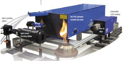
ResearchGateSee discussions,stats, and author profiles for this publication at: https://www.researchgate.net/publication/272399959 Flame B: attached, V-shaped, without PVC Formation and flame-induced suppression ofthe precessing vortex core in a swirl combustor:Experiments and linear... Article in Combustion and Flame· May 2015 DOI:10.1016/j.combustflame.2015.02.015 CITATIONS 19 READS190 5 authors,including: Kilian Oberleithner Adam Michael Steinberg Technische Universitat Berlin University of Toronto 51 PUBLICATIONS 321 CITATIONS 76 PUBLICATIONS 418 CITATIONS SEE PROFILE SEE PROFILE ( The user has requested enhancement of the downloaded file. All in-text references underlined in blue are added to the original document and are linked to publications on ResearchGate, letting you access and read them immediately. ) K. Oberleithner, M. Stohr, S.H. Im, C.M. Arndt, A.M. Steinberg, Formation andflame-induced suppression of the precessing vortex core in a swirl combustor:Experiments and linear stability analysis, Combustion and Flame 162 (2015) 3100- 3114 The original publication is available at www.elsevier.com http://dx.doi.org/10.1016/i.combustflame.2015.02.015 Formation and flame-induced suppression of theprecessing vortex core in a swirl combustor:experiments and linear stability analysis Kilian Oberleithner*, Michael Stohrb, Seong Ho Im, Christoph M. Arndt,Adam M. SteinbergD,c "Institut fiir Stromungsmechanik und Technische Akustik, HFI,Miiller-Breslau StraBe 8, 10623Berlin, Germany German Aerospace Center (DLR), Institute of Combustion Technology, Pfaffenwaldring 38-40, 70569 Stuttgart, Germany ‘Present address: Institute for Aerospace Studies, University of Toronto, 4925 Dufferin St.,Toronto, Canada M3H 5T6 Abstract The precessing vortex core (PVC) is a coherent flow structure that is often encoun-tered in swirling flows in gas turbine (GT) combustors. In some swirl combustors,it has been observed that a PVC is present under non-reacting conditions but dis-appears in the corresponding reacting cases. Since numerous studies have shownthat a PVC has strong effects on the flame stabilization,it is desirable to under-stand the formation and suppression of PVCs in GT combustors. The present workexperimentally studies the flow field in a GT model combustor at atmosphericpressure. Whereas all non-reacting conditions and detached M-shaped flames ex-hibit a PVC, the PVC is suppressed for attached V-shaped flames. A local linearstability analysis is then applied to the measured time-averaged velocity and den-sity fields. For the cases where a PVC appeared in the experiment, the analysisshows a global hydrodynamic instability that manifests in a single-helical modewith its wavemaker located at the combustor inlet. The frequency of the globalmode is in excellent agreement with the measured oscillation frequency and thegrowth rate is approximately zero, indicating the marginally stable limit-cycle.For the attached V-flame without PVC, strong radial density/temperature gradi-ents are present at the inlet, which are shown to suppress the global instability.The interplay between the PVC and the flame is further investigated by consid- ( *Corresponding author. Email: oberleithner@tu-berlin.de ) ering a bi-stable case with intermittent transitions between V- and M-flame. Theflame and flow transients are investigated experimentally via simultaneous high-speed PIV and OH-PLIF. The experiments reveal a sequence of events whereinthe PVC forms prior to the transition of the flame shape. The results demonstratethe essential role of the PVC in the flame stabilization, and thereby the importanceof a hydrodynamic stability analysis in the design of a swirl combustor. Keywords: precessing vortex core, turbulent swirl flames, linear hydrodynamicinstability, coherent structures 1. Introduction In modern gas turbine (GT) combustors, the flames are commonly stabilizedaerodynamically by imposing a swirling flow on the reactants. Vortex breakdownthat manifests in the combustion chamber leads to the formation of an inner recir-culation zone (IRZ), where hot burned gas is mixed with the unburned reactants.This enhances ignition of the unburned gas and thus helps to operate the flamesunder the required fuel-lean and highly turbulent conditions. The formation of the IRZ is often (but not always) accompanied by the oc-curence of coherent flow structures such as the precessing vortex core (PVC). ThePVC is characterized by a periodical off-axis precession of the center of rota-tion [1]. Numerous studies have shown that PVCs affect the stabilization of swirlflames in various ways. For instance, the PVC can lead to enhanced fuel-air mix-ing [2, 3, 4, 5], enhanced mixing of burned and unburned gas [6, 7] and roll-up,stretch or local quenching of reaction zones [7, 8]. The PVC may also interactwith thermoacoustic oscillations of the flame [9, 10]. Due to these strong effectson the flame, it is desirable to assess the occurence or absence of a PVC duringthe design of a combustor. In some GT combustors, PVCs are encountered for both non-reacting andreacting conditions [11, 12, 13, 7]. In other combustors, the PVC forms for non-reacting cases, while it is suppressed for certain, but not necessarily all reactingcases [14, 15,16,17,18]. It was further observed that the suppression of the PVCin a swirl flame can be triggered by changes of steam content and preheat tem-perature [19], swirl number [20], thermal power [21],pilot flow rate [22], or axialair injection [23]. The suppression of a PVC in a flame is usually accompaniedby a major change of the flame shape [20], which in turn affects the combustorperformance in terms of thermoacoustics,NOx emissions, flashback or blowout. The occurrence of a PVC is not limited to combustor flows but was reportedin all types of swirling flows [24]. Since the early literature, it was distinguishedbetween a steady, axisymmetric bubble type vortex breakdown and an unsteady,helical spiral vortex breakdown [25, 26]. Later investigations came to the conclu-sion that vortex breakdown is essentially axisymmetric, and the so-called spiraltype vortex breakdown is a superposition of the axisymmetric vortex breakdownand a helical flow instability[27]. Following Benjamin [28] and Squire [29],vortex breakdown is caused by the criticality of the vortex core and not by thehydrodynamic stability. The formation of vortex breakdown and associated heli-cal instabilities were further investigated analytically for swirling pipe flows [30],through direct numerical simulations of laminar swirling jets [31] in conjunctionwith a linear stability analysis [32, 33, 34], and through experimental investiga-tions of laminar [35] and turbulent [36, 37] swirling jets. All these studies confirmthat vortex breakdown occurs due to the criticality of the vortex core and remainsaxisymmetrical until the onset of a super-critical Hopf bifurcation to a helical hy-drodynamic global instability, which manifests in the PVC. Although these findings are well established in fundamental research, the con-cept of global instability has only recently entered the combustion community.This is attributed to the fact that combustor flows are typically highly turbulentand feature strong density fluctuations, which make flow-instability considera-tions less apparent. Yet, from fundamental flow studies, it is known that the den-sity field has a significant impact on the flow stability [38, 39]. In particular, itwas shown that the suppression of the PVC at certain operating conditions can berelated to the change of the density field [40, 41]. The aim of the present work is to characterize and explain the formation andsuppression of the PVC in a GT-typical swirl combustor by means ofexperimentsand linear stability analysis. Velocity fields, density distributions, and the occur-rence and frequency of the PVC are measured for ranges of thermal power andequivalence ratio. While the non-reacting flows in the combustor always featurea PVC, the PVC is suppressed at certain reacting conditions. Stability analysis isequipped with an eddy viscosity model and applied to the time-averaged turbulentflow. As already mentioned by Juniper [42], the stability analysis of the meanflow is an analytic tool, revealing the mechanisms that drive the instability at itslimit-cycle. In this article the analytic approach is described in detail, and then applied toone non-reacting and two reacting cases (with and without PVC). For each case,the occurrence and, if present, the frequency of the PVC is evaluated from the sta-bility analysis and compared to the measurements. The analysis reveals regions of absolute instability that drive the global mode and identifies the so-called globalemode wavemaker that determines the PVC frequency and growth rate. For thereacting cases, the influence of the density field on the suppression of the PVC isexamined. Finally, the transient dynamics of flow and reaction is studied usinghigh-speed laser diagnostics at an operating condition where the PVC appears in-termittently. By analyzing the transient dynamics in combination with the resultsof the LSA, the complex interplay of the flow/density field, hydrodynamic insta-bility and flame propagation is examined that governs the stabilization of turbulentswirl flames. 2. Combustor and measuring techniques 2.1. Gas turbine model combustor Experimental studies were performed in a gas turbine model combustor de-rived from an industrial design by Turbomeca, which can be operated in a partiallypremixed [43, 44] and a perfectly premixed [21] configuration. In this work, thecombustor is operated at atmospheric pressure with perfectly premixed methaneand air as shown in Fig. 1. The reactants first enter the plenum and the assthrough a swirl generator with 12 radial vanes. The swirling flow then enters thecombustor chamber through a burner nozzle with a diameter of D= 27.85 mm anda conical inner bluff body. The chamber has a square cross-section of 85×85 mm"and a height of 114 mm. Optical access to the chamber is provided by side wallsmade of quartz glass held by metal posts in the corners. The exit is composed ofa conical part followed by an exhaust duct with 40 mm inner diameter. Cartesian coordinates are used for the measurements with the position vectorx=(x,y,z)" and corresponding velocity vector u=(ux,Uy,uz), while cylindricalcoordinates are used for the stability analysis with the position vector x=(x,r,0)and the corresponding velocity vector u= (ux,Ur,ue). The orientation of bothcoordinate systems is indicated in Fig. 1, with the x-axis centered to the combustorinlet and orientated in streamwise direction. 2.2. Particle image velocimetry Three-component velocity fields were measured using stereoscopic particleimage velocimetry (PIV)with a repetition rate of 5 Hz. The system (FlowMaster,LaVision) consisted of a frequency-doubled dual-head Nd:YAG laser (New WaveSolo 120, 120 mJ per pulse at 532 nm), two double-shutter CCD cameras (LaVi-sion Imager Intense, 1376x1040 pixels) and a programmable timing unit (PTU 9,LaVision). The laser beam was expanded to a light sheet that covered the central Figure 1: Side view of gas turbine model combustor. vertical section of the combustion chamber. The thickness of the laser sheet wasaround 1 mm. The cameras were equipped with a wide-angle lens (f=16 mm,set to f/2) and a bandpass filter (532±5 nm) in order to reduce the influence offlame luminosity. Both cameras were mounted on Scheimpflug adapters in orderto align their focal plane with the laser sheet. The two cameras were located asclose as possible to the combustor in order to image the full vertical section ofthe chamber (marked in Fig. 1) with a reasonably large stereoscopic angle. In thepresent configuration, the distance between the camera lenses and the measure-ment plane was 20 cm, and the angle of view of the cameras was 20°. An infraredfilter was mounted between the combustor and the cameras in order to protect thecamera from thermal radiation. The air flow was seeded with TiO2 particles witha nominal diameter of 1 um, which have a relaxation time of t~5·10-6s. For thecondition with the highest flow rate, the maximal local velocities are v~60 m/sand the typical length scale is l~10 mm. The resulting Stokes number is "=0.03,and thus velocity errors due to particle slip are considered negligible. Velocity fields were evaluated from particle images using a commercial PIVsoftware (LaVision Davis 8.0). A multi-scale cross-correlation algorithm wasused with a final interrogation window size of 16x16 pixel (corresponding to anin-plane spatial resolution of 1.3×1.3 mm²) and a window overlap of 50%. Based on the ±0.1 pixel uncertainty of the peak-finding algorithm, the estimated randomuncertainty of in-plane instantaneous velocities is ±0.8 m/s. With the camera an-gle of 20°, the uncertainty of the out-of-plane velocity is about three times higheras for the in-plane uncertainty [45]. 2.3. Chemiluminescence imaging Line-of-sight integrated imaging of OH chemiluminescence (CL) was per-formed using an intensified CMOS camera (LaVision HSS8 with HS-IRO) equippedwith a Cerco UV lens (f=45 mm, f/1.8) and a bandpass filter (300-325 nm). Thefield of view was the whole cross-section of the combustion chamber. Dependingon the operating condition, the intensifier gate time and the frame rate varied from40 us and 5 kHz to 12 us and 10 kHz, respectively. 2.4. Pressure recording Pressure signals from the combustion chamber were recorded in order to de-termine the precession frequency of the PVC. The pressure in the chamber wasmeasured using calibrated microphone probes equipped with B&K Type 4939condenser microphones.Two pressure signals, pi(t) and p2(t), were acquiredfrom two opposite corners in the combustion chamber at a height of x=15 mm.The signals were recorded simultaneously using a multichannel A/D converterwith a sampling rate of 50 kHz. As described in Ref. [7], the difference signal△p(t)= pi(t)- p2(t) contains the pressure history of the PVC, and therefore canbe used to determine the frequency and phase angle of the PVC precession. 2.5. Highspeed PIV and OH-PLIF Simultaneous OH planar laser-induced fluorescence (PLIF), stereoscopic PIVand OH-CL imaging was performed at a repetition rate of 10 kHz. Due to limita-tions of laser pulse energy and camera resolution, the fields of view are reducedcompared to the 5 Hz PIV as shown in Fig. 1. Details of the setup can be foundin Ref. [21] and only a short overview is provided here. The OH-PLIF system consisted of a frequency-doubled dye laser (Sirah Credo),pumped by a Nd:YAG diode-pumped solid state (DPSS) laser (Edgewave IS8II-E). The dye laser was tuned to the Qi(7) transition in the A-X(1,0) band of OH at283.2 nm, with a pulse energy of 0.18 mJ in the UV. The laser beam was expandedinto a sheet with a height of approximately 50 mm using a two-stage cylindricaltelescope and focused into the test section with a third cylindrical lens, resulting ina sheet thickness of approximately 0.4 mm. The PLIF signal was collected with anintensified high-speed CMOS camera (LaVision HSS 5 with LaVision HS-IRO) equipped with a fast UV lens (Cerco, f=45mm, f/1.8) and a bandpass filter (300-325 nm). A second, identical camera/lens/filter arrangement was used for OH-CLimaging with intensifier gate times between 15 us and 25 us depending on thecondition. The stereoscopic PIV system consisted of a dual-cavity Nd:YAG DPSS laser(Edgewave IS6II-DE) with a pulse energy of 2.6 mJ/pulse at 532 nm. The laserbeam was expanded into a light sheet with a two-stage cylindrical telescope andfocused into the test section using a third cylindrical lens, resulting in a sheetwith a height of approximately 40 mm and a thickness of approximately 1 mm.Mie scattering of titanium dioxide particles was imaged with apair of high-speedCMOS cameras (LaVision HSS 8), equipped with commercial camera lenses(Tokina, f=100 mm, set to f/5.6). Vector fields were computed from the particleimages using a commercial PIV software (LaVision DaVis 8.0) with a multi-scalecross-correlation algorithm. The resulting final interrogation window size was16×16 pixels (corresponding to an in-plane spatial resolution of 1.0×1.0 mm)with a window overlap of 50%. 3. Experimental results 3.1. Flame shapes and occurrence ofthe PVC Flames were characterized using OH-CL imaging and pressure recording forthermal power Pth ranging between 10 and 35 kW and equivalence ratios o be-tween 0.65 and 1. The OH-CL images, which are considered as a marker of theflame zone [46], are shown in Fig. 2a. The images show two main types of flameshape, namely the M-shaped flame type (conditions marked with the red envelope)and the V-shaped type in the remaining range of conditions. While the V-shapedflames are generally attached to the burner nozzle, the base of the M-shaped flamesis lifted approximately 10 mm above the nozzle. There are also three transitionalcases (marked with an asterisk), where the flame alternates randomly between V-and M-shape (the typical time between shape-changes is on the order of 1 s). The occurrence of a PVC was detected using the power spectrum of the pres-sure difference signal as described in Sect. 2.4. If present, the PVC exhibits acharacteristic peak at its precession frequency fpvc. For the cases where a PVCwas observed, the values of fevc are specified in the table shown in Fig. 2b. Com-paring the occurrence of the PVC listed in Fig. 2b with the flame shapes in Fig. 2areveals that a PVC always occurs for the M-shaped flames, whereas the V-shapedflames generally do not exhibit a PVC. For the three transitional cases (marked Figure 2: (a) Flame shapes for different values of thermal power Pth and equivalence ratio o. Theconditions where a PVC occurs are marked red. (b)Precession frequencies of the PVC detectedin the acoustic spectrum. with an asterisk), the PVC appears in the acoustic spectrum only during the peri-ods when the flame is in M-shape. Non-reacting conditions have been measured ina previous work by Steinberg et al. [21] for thermal powers in the range Pth=10-35kW, and for all cases a PVC was found. The variation of fpvc versus the volumetric flow rate g of premixed air andmethane is plotted in Fig. 3 (the values for non-reacting cases were adopted fromRef. [21]). While the frequencies under reacting conditions are slightly higherthan for non-reacting flows, fevc increases in both cases linearly with Q, whichis consistent with previous results from other swirl burners [1, 11,47, 13, 7]. Forthe last reacting case with Pth=35 kW and d=0.65, the frequency of 855 Hz isslightly lower than the linear fit. According to the discussion later in Sect. 6,this might be caused by density changes due to the presence of the flame nearthe nozzle as seen in the respective CL image in Fig. 2a. From the linear fitsthe resulting Strouhal number Stpvc = fpvcD/Uo, based on the nozzle diameterD and the average velocity Uo through the nozzle, is 0.93 and 0.78 for reactingand non-reacting conditions, respectively. It is noted that values of St for PVCsdepend, e.g., on the geometry of swirl generator and injector nozzle (see Ref. [7]for a compilation of literature values), and therefore the stated values are validonly for the present combustor. Figure 3: Variation of PVC frequency fevc versus volumetric flow rate Q. Values for non-reactingcases were adopted from Ref.[21]. 3.2. Characterization of selected operating conditions The results discussed in Sect. 3.1 showed that a PVC is present for all non-reacting flows and M-shaped flames, whereas no PVC is found for the V-shapedflames. The analysis of formation and suppression of the PVC in this work there-fore focuses on four representative conditions labeled as A, B, C and D, which arespecified in Table 1. The non-reacting case A at Pth=15 kW and d=0.7 exhibits aPVC at 305 Hz, which disappears in the corresponding reacting condition B wherea V-shaped flame is formed as seen in Fig. 2. The reacting case C at Pth=25 kWand d=0.7, by contrast, exhibits an M-shaped flame with a PVC at 595 Hz. Inthe remainder of this section, cases A, B and C are characterized in terms of ve-locity field, flame shape and density distribution. A linear stability analysis willbe applied to these cases in Sects. 4-6. Case D is a transitional flame alternatingbetween an M-shaped form with PVC and a V-shaped form without PVC, whichwill be studied by means of time-resolved measurements in Sect. 7. The measured time-averaged velocity fields for the cases A-C are shown inFig. 4. All three cases have the typical structure of a confined swirl flow withvortex breakdown, consisting of a cone-shaped jet of unburned gas entering at thebottom, an IRZ and an outer recirculation zone (ORZ). For the non-reacting caseA, the opening angle of the jet is relatively low, but increases notably at the heightof x/D~1.5. This leads to an IRZ with an inverted bell-shape and a relatively largeORZ. Flame B has a jet with a wider opening angle, and consequently exhibits alarger IRZ and smaller ORZ. Compared to flame B, flame C features a slightlyreduced jet opening angle and, most notably, a significantly smaller IRZ. For allthree cases, high azimuthal velocities occur in the swirling jet above the nozzle Case A B C D React./ Non-react. non-react. react. react. react. Pth kW 15 15 25 20 0.7 0.7 0.7 0.7 Flame - V-shape(attached) M-shape V/M-shape shape (alternating) (detached) Uo [m/s] 10.8 10.8 18.1 14.4 fpvc Hz| 305 595 -/490 Stpvc 0.78 一 0.92 -/0.92 Table 1:Operating conditions used for stability analysis. and near the exhaust duct contraction at the top. The dominant unsteady coherent structures of a flow in terms of kinetic en-ergy were determined using a Proper Orthogonal Decomposition (POD) of theinstantaneous velocity fields as described, e.g., in Refs. [6, 36]. The three mostenergetic POD modes for the three conditions are shown in Fig. 4 together withpercentage values denoting their contribution to the total unsteady kinetic energyin the measurement domain. For cases A and C, the first two modes exhibit vortexpatterns that represent the coherent helical PVC located in the inner shear layer(ISL) of the swirling jet. As shown in previous works (e.g., [36, 6]), the twomodes with a phase shift of 90° represent the precession of the PVC helix, whichcorresponds to a periodic streamwise motion of vortices in the measuring plane.Any intermediate position of the vortices can be represented by an appropriatelyweighted linear combination of the two modes. As expected, no vortex patternsin the ISL are seen in the POD modes of case B. Details of the V-shaped flame B and M-shaped flame C are shown in the time-averaged OH-CL images included in Fig. 5. Based on the approximately rota-tional symmetry of the average flame shape, the original line-of-sight integratedCL images have been Abel-deconvoluted to obtain the 2D distributions of heatrelease in the symmetry plane. The planar distributions show that flame B is an-chored near the central bluff body and is stabilized in the ISL up to a height ofx/D~2.5. Flame C, on the other hand, is lifted ~0.5Dabove the nozzle exit, andextends across the full chamber width up to x/D~2.5. Figure 4: Average flow field and first three POD modes for the three selected operating conditions.The percentage values indicate the contribution of the POD mode to the total turbulent kineticenergy. 3.3. Instantaneous flow fields and flame structures Figure 6 shows an instantaneous flow field and OH-PLIF measurement forthe two reacting cases B and C. For flame B, where no PVC is present, the flowfield shows a wide IRZ that is largely symmetric with respect to the central axisy=0. The flow field of flame C, by contrast, exhibits the asymmetric zig-zag pat-tern of vortices that represents the 3D helical PVC. In the grayscale OH-PLIFimages, different zones of the flame can be distinguished according to the level ofOH. Regions without OH (black) represent gas with low or medium temperature(T<1500 K), i.e., unburned gas possibly mixed with adjacent burned gas. Highlevels of OH (light gray to white) indicate superequilibrium OH, which is formedin the reaction zones and has a half-life period of~1 ms under atmospheric pres-sure conditions [48]. Regions with medium and low levels of OH (medium and Figure 5: Average OH-CL and average density field for the two reacting conditions B and C. dark gray) represent burned gas where the OH concentration has decayed towardequilibrium while it was transported away from the reaction zone. The OH images show that the structures of the two flames are fundamentallydifferent: For flame B, reaction zones are mainly encountered at the boundarybetween the jetofunburned gas and the burned gas in the IRZ. Reaction zones andthe IRZ extend down to the dump plane (x=0), indicating that the flame is attachedat the nozzle lip. Flame C, on the other hand, exhibits a zone of unburned gasabove the nozzle showing that the flame is detached. High OH levels indicatingreaction zones are found in the IRZ at heights x/D>0.5 and in the ORZ. In theIRZ it is seen that the PVC causes a roll-up of the reaction zone. As an importanteffect, the different structures of flame B and C involve different distributions ofdensity, which are discussed in the following section. It is important to note that the PVC induces an unsteady lower stagnation point(LSP) inside the IRZ (marked with a dot in Fig. 6b), which rotates with the PVCand does not correspond to the stagnation point of the time-averaged flow fieldthat is located at the upstream end of the IRZ. The unsteady LSP is importantbecause it roughly determines the location of the flame root as shown in a recentstudy [7]. The M-shaped flame is lifted accordingly. The V-shaped flame without Figure 6: Instantaneous PIV and OH-PLIF measurements for flames B and C. PVC, by contrast, does not exhibit a LSP in the IRZ and, as a result, the flame isattached at the bluff body (Fig. 6a). 3.4. Density distribution ofreacting cases Besides the time-averaged flow field, the linear stability analysis that will bediscussed in Sects. 4-6 also requires the time-averaged distribution of density inthe flow. While the density is approximately uniform for the non-reacting caseA, the reacting cases B and C exhibit strong density variations due to thermal ex-pansion of the unburned gas. For these cases the density was determined usingthe quantitative light sheet (QLS) technique[49, 40,19]. As the QLS techniquederives the density from the Mie scattering signal of the PIV particles, the par-ticle images recorded for the velocity measurements were used for the densityestimation. The calibration of the QLS signal is based on the maximum densityoccurring in the jet of unburned gas near the nozzle, which is set to a value ofpo=1.16 kg/m’determined with GasEq [50] for T=20 °C. The resulting densitydistributions for cases B and C are shown in Fig. 5. For flame B, high densitiesare found in the jet of unburned gas (cf. Fig. 4), whereas low-density burned gasis present in the IRZ and ORZ. This creates strong radial density gradients nearthe nozzle lip. For the lifted flame C, by contrast, high-density unburned gas withsmooth radial gradients is found in a wide area above the nozzle within x/D<0.5 and ly/D|<0.5. 4. Theoretical method for the analysis of PVC formation 4.1. The PVC as a global hydrodynamic instability mode Numerous previous investigations have shown that the PVC encountered inreacting and non-reacting swirling jets is a manifestation of a super-critical Hopfbifurcation to a global mode [35, 32, 31, 36,37,34,40,41]. Generally, a globalinstability mode is characterized by a single oscillation frequency and shape func-tion, it is self-sustained, and it is robust to external forcing [51, 52]. For globalmodes to exist, an internal feed-back mechanism must be established that feedsonto the self-excited oscillations. The most prominent example for a global modeis the Kármán vortex street in the wake of a circular cylinder [53,54]. Thereby,the recirculation zone in the wake promotes the upstream propagation of flow per-turbations. By exceeding a critical Reynolds number, the wake becomes linearlyunstable and the flow, if perturbed, undergoes a super-critical Hopf bifurcationto an oscillating state - the Kármán vortex street. A similar scenario applies tothe swirling jet undergoing vortex breakdown. Here, the feedback is promotedthrough the recirculating flow in the vortex breakdown bubble (or the IRZ). Withincreasing swirl, the bubble increases in size until it becomes linearly unstable,and the (perturbed) flow bifurcates to an oscillatory state that manifests in a spi-raling motion - the PVC [35, 31,36,37,32]. In this work, we consider the baseflow as given, ignoring the mechanisms that lead to its formation. The presentanalysis rather focuses on the flow oscillations that are the consequence of thisbase flow. 4.2. Stability equations for turbulent flows The PVC is investigated theoretically by means of triple-decomposition lin-ear stability analysis. Therefore, the instantaneous flow field vector u(x, t) is de-composed into a time-averaged part u(x), a periodic (coherent) part u(x,t), and arandomly fluctuating (turbulent) part u"(x,t), reading The phase-average (u(x,t)) is used to separate the fine-scale turbulent fluctuationsfrom the coherent motion such that ǔ(x,t)=(u(x,t))-u(x). The triple decomposition is substituted into the incompressible Navier-Stokesequation and the continuity equation, and, after some manipulations, the govern-ing equations for each of the three parts can be formulated [55]. The mean flowequations are indicating how the mean flow is modified through the generation of turbulent andcoherent Reynolds stresses. The equations for the coherent motion are given as where the nonlinear terms r= iǔ- iǔ are neglected in the following. Theterms t=(u"u")-uu"=u’u’ represent the modification of the turbulent fieldduring the passage of a coherent structure. These turbulent-coherent interactionsare unknown and must be modeled appropriately. The mean-coherent and mean-turbulent interactions are reflected in the actual mean flow shape and are implicitlyaccounted for in the perturbation equations(3). 4.3. Calculation ofeddy viscosity The turbulent-coherent interactions are modeled through a Newtonian eddyviscosity model where vr is the eddy viscosity of the undisturbed flow and the indices i, j = 1,2, 3indicate the three velocity components. In swirling flows, several Reynolds stresscomponents are relevant and the eddy viscosity is approximated through a least-square fit over all resolved Reynolds stresses [56], yielding with the summation over the repeating indices i, j,k, and l =1,2,3. For evaluation purposes, the stability analysis is also conducted for other (sim-plified) turbulence models that were used in previous studies. One common sim-plification is to derive the eddy viscosity from the total fluctuating field not dif-ferentiating between the coherent and non-coherent fluctuations. The formulationfor the eddy viscosity then reads as where u’ refers to the velocity fluctuations according to the classic Reynolds de-composition, u=u+u’. This simplification was adopted recently for the stabilityanalysis of a turbulent jet at zero to moderate swirl, showing good quantitativeagreement [57]. These jet flows feature a wide spectrum of instability waves andthe contribution of each mode to the total fluctuation budget was small, and theturbulence model based on the total fluctuation field seems legitimate. Viola etal. employed the same approach for the stability analysis of a wind turbine wake[58]. They showed close correlations with the measured frequency of a dominantcoherent structure, but they did not quantitatively compare the predicted growthrates. In wake flows, coherent structures are typically more distinct and occurwithin a small frequency band and the application of the Reynolds decompositionremains questionable at this point. Another simplification is to assume the flow to be quasi two-dimensional andto consider only one entry of the turbulent stress tensor. Considering only theshear generated by the axial velocity profile, the eddy viscosity model reads as This model was implemented for the spatial stability analysis of a swirl-stabilizedflame [40, 59], yielding inaccurate predictions of the growth rates, but good pre-dictions of frequencies. 4.4. Determining the global instability For a global stability analysis, equation (3) is solved for a perturbation havingthe form with the complex three-dimensional shape function ú and the complex globalmode frequency wg=Wgr+iwg,i. The global mode growth rate and frequency is determined by the real and imaginary part ofwg, and the entire flow field is saidto be globally unstable if wg,i> 0. Introducing (8) into (3) leads to a stability eigenvalue problem, which caneasily reach impractical size [60]. To reduce the numerical effort, the stabilityproblem (3) is first solved locally and the global stability properties are thereafterdeduced from the local stability properties. The same approach has recently beenadopted in several related studies dealing with swirling and non-swirling wakeflows [61,36,42,40,41,34,62]. A local eigenvalue problem is posed by adoptinga quasi parallel, axially symmetric velocity profile where uy and ug are the axial and azimuthal velocity component, respectively. Ina parallel flow, the radial component ur(r) is set to zero to satisfy the continuityequation. For the parallel flow, the perturbation is homogeneous in the streamwise and azimuthal directions. Here a denotes thecomplex streamwise wavenumber, w the complex frequency, and m the real az-imuthal wavenumber. In this work we solve for the m = 1 mode, which corre-sponds to a single-helical instability. The local stability is linked to the global stability through the concept of con-vective and absolute instability [51]. A convective instability is swept away fromits source leaving the flow ultimately unperturbed. An absolute instability growsin the upstream and downstream directions, ultimately perturbing the entire par-allel flow. The convective/absolute instability is determined through the impulseresponse to a localized perturbation. If the resulting wavepacket spreads in theupstream and downstream directions, the parallel flow is considered as absolutelyunstable. For large times, the impulse response is determined by the wave at zerogroup velocity dw/da=0, which is the necessary condition for a saddle pointin the complex alpha plane. The complex frequency at this saddle point is calledthe absolute frequency wo =wo,r+iwoi. The flow profile is absolutely unstable ifwo,i> 0 and absolutely stable if wo,i <0. In this work, the absolute frequency is determined for each streamwise loca-tion using a so-called spatio-temporal analysis where the local eigenvalue prob-lem is solved for complex w and complex a. The saddle point in the a plane isdetermined by minimizing the functional F=(0w;/0o,)+(0w;/0a;). Detailsof the numeric scheme are given in [63, 36, 40]. Once the absolute frequency is computed for the profiles at each streamwise station, the global stability is derivedfrom the resulting streamwise distribution of wo. The local and global stability areconnected through the concept of the global mode wavemaker. At the streamwiselocation of the wavemaker, the global mode frequency and growth rate is equal tothe local absolute growth rate. There are two criteria that define the position ofthe wavemaker 51,52. 1.A region ofabsolute instability is nested in a region of convective instability:The global mode frequency is then given by the saddle point criterion which involves an analytical continuation of wo(x) in the complex x plane.The streamwise location x, determines the location of the global modewavemaker where the global mode frequency wgr and growth rate wg,i isdetermined. 2. The region ofabsolute instability is attached or close to the flow inlet: Thewavemaker is located at the inlet and the global mode frequency and growthrate is equal to the absolute frequency at the inlet The first scenario applies to the Karmán vortex street [61] and swirling jetswith a detached vortex breakdown bubble [32, 40, 41]. In this work, both criteriacome to play depending on specific combustor operating conditions. 5. Stability analysis of the isothermal flow -the benchmark case The linear stability analysis is first applied to the flow field at isothermal condi-tions (case A). It serves as a test case for the stability analysis and for the adoptedturbulence model. Figure 7 shows the measured mean flow field and the mea-sured eddy viscosity utilizing eq. (5). As discussed in Sect. 3.2, the mean flowfield is characterized by a cone-shaped swirling jet with an IRZ and ORZ. Theflow features a self-excited PVC with a frequency of 305 Hz. The eddy viscositydistribution indicates strong turbulent fluctuations at the combustor inlet and in theregion where the annular jet impinges the combustor walls. In these regions, theeddy viscosity is three orders of magnitude higher than the molecular viscosity. Radial profiles of the mean flow and eddy viscosity distribution are extractedfor each streamwise location and fed into the stability solver. The absolute fre-quency wo is then derived from a spatio-temporal analysis of these profiles as Figure 7: Isothermal flow (case A): (a) contours of magnitude of the mean velocity and (b) theeddy viscosity v derived from the triple-decomposed PIV measurements according to equ. (5).The mean flow streamlines indicate the inner and outer recirculation zones explained in Sect. 4.4. Figure 8 shows the real and imaginary part of the absolutefrequency versus streamwise distance. In order to verify the turbulence models, computations were conducted for aquasi-laminar flow with Re = UD/v and for the turbulent flow using the threedifferent eddy viscosity models described in Sect.4.3. For the quasi-laminarmodel, the absolute growth rate wo,i is highest at the inlet and decreases contin-uously with downstream distance featuring a very large region of absolute insta-bility (wo,>0). When the fine-scale turbulence is taken into account, the growthrate is significantly decreased, as the additional viscosity generally dampens thistype of instability. For the most comprehensive eddy viscosity model v (tripledecomposition and least-square fit over all Reynolds stress components), the flowfeatures a confined region of absolute instability with a transition from convectiveto absolute instability right at the combustor inlet. For both, the quasi-laminarand the turbulent flow analysis,the region of absolute instability is attached to theinlet. For this scenario the wavemaker is located at the upstream boundary of theabsolute unstable region, which is right at the combustor inlet. The global modefrequency and growth rate are then given by the real and imaginary part of the ab-solute frequency at the inlet with wg=wo(x=0). The resulting global oscillation frequencies f=wgr/2n with and without the turbulence model are 306 Hz and 297Hz, respectively. The value obtained with the turbulence model coincides remark-ably well with the measured PVC oscillation frequency of 305 Hz (marked by thehorizontal black line in Fig. 8). The quasi-laminar computations (Re = UD/v)predict a globally unstable flow with wgi =wo,i(x= 0)> 0, while the calcu-lations with the turbulence model predict a globally marginally stable flow withωgi = wo,i(x=0)~ 0. The prediction of a marginally stable global mode isin good agreement with the mean field model proposed by Noack et al. [64] thatwas later confirmed numerically [65] and experimentally [66]. According to meanfield theory, the limit-cycle oscillations of the global mode are accurately repre-sented by a marginally stable global mode of the mean flow. Considering the simplified eddy viscosity models with 2and v, given byequations (6) and (7), respectively,strong variations near the inlet become evident(see Fig.8). The growth rates are significantly lower than for the comprehensivemodel yr, whereas the frequencies remain unchanged. Now, the region of absoluteinstability is detached from the inlet and the global mode wavemaker is deter-mined from criterion (11). This would yield a wavemaker located at x/D≈0.6and a global mode frequency ofwr ~ 1.2, which is far below the measured limit-cycle. In fact, for both models, the correct frequency is still selected at the inlet,but the growth rates there are strongly underestimated. The present results suggest that the predicted absolute frequency does not de-pend on the turbulence model, but for a correct prediction of the growth rates theadditional damping through the small-scale fluctuations must be considered. Thisis consistent with previously conducted stability analysis of similar configurations(with simplified or no turbulence models), where the predicted growth rates werewrong, but the frequencies were predicted correctly [42, 40, 23, 41,59]. The goodestimation of the limit-cycle gives credibility to the present turbulence model. The theoretical prediction is further validated by comparing the actual shape ofthe instability waves with the phase-averaged flow quantities. Therefore, the localeigenvalue problem is solved for the given global frequency wg at each streamwiselocation. This so-called spatial stability analysis provides spatially growing (a; <0) and decaying (i>0) instability waves for a given perturbation frequency.Figure 9 shows the results of this analysis for two selected profiles. Depictedare the amplitude distribution of the radial coherent velocity fluctuations at thecombustor inlet (x/D =0.04) and at a downstream location where the vortexshedding is strong (x/D=0.8). At the inlet, the PVC is clearly indicated by thepeak in the radial velocity magnitude on the jet centerline. This particular shapeis well reproduced by the local stability eigemode at this streamwise location. At Figure 8: Isothermal flow: absolute growth rate (a) and frequency (b) derived from the linearstability analysis. Computations are conducted for a quasi-laminar flow with Re =UD/v and fora turbulent flow with Re=UD/(v+v). For validation purpose, computations are repeated forsimplified eddy viscosity models andv, as given by equ. (6-7).The measured PVC frequencyis indicated by the black horizontal line (b). The global mode wave maker is locate at the inletwith wg=wo(x=0). Figure 9: Profiles of the magnitude of the coherent radial velocity fluctuations derived from PIVand linear stability analysis. Profiles are taken at the most upstream measurement point and furtherdownstream indicating the PVC at the inlet and the large-scale helical fluctuations in the shearlayers further downstream. x/D=0.8, fluctuations are concentrated in the periphery of the IRZ where theshear layers roll up to a helical vortex (see also Fig. 4). There the radial velocityfluctuations peak in the center of the annular jet at r/D= 0.75, which refers tothe radial displacement of the entire annular jet column during the passage of acoherent structure. Again, these dynamics are very well captured by the stabilityeigenmode at this streamwise station. Besides the evaluation of the turbulence model, the analysis of the isothermalflow already indicates the importance of the inflow profiles for the formation ofthe PVC. With the wavemaker located at the inlet, the PVC frequency and growthrate strongly depend on the inflow conditions. Yet, the global flow oscillationsare still driven by the downstream located region of absolute instability and asso-ciated upstream propagation of instability waves. Moreover, the analysis of theisothermal flow clearly demonstrates that the PVC at the inlet and the large-scalehelical structures in between the IRZ and the ORZ correspond to the same globalinstability mode. 6. Stability analysis of the reacting flow - flame-induced suppression of thePVC In this section, a stability analysis is performed for the reacting cases B andC. As discussed in Sect. 3.2, case B corresponds to the attached V-shaped flamewithout PVC, and case C corresponds to the detached M-shaped flame featuringa PVC at 595 Hz. The density fields displayed in Fig. 5 show that the attachedflame B exhibits a strong radial density stratification at the nozzle lip, whereas thelifted flame C features smooth radial density gradients near the burner nozzle. The density field contributes to the pressure term of the stability equations(3) and through a modification of the kinematic viscosity. Due to the baroclinictorque, the stratification of density may crucially affect the growth rates of theinstability. A radial density gradient that is co-signed with the radial gradient ofaxial velocity acts typically dampening on the instability and vice versa. As a con-sequence, the density field destabilizes hot jets and cold wakes while it stabilizescold jets and hot wakes [38, 39]. In swirl-stabilized combustion, the cold annularjet emanates into the hot combustion chamber. If the flame is located close to theinlet, the temperature difference between the incoming unburned gas and the reac-tants in the IRZ form a strong radial density gradient. The resulting hot wake flowis thereby more stable than the isothermal flow, which may lead to the suppressionof the PVC [40, 41]. In contrast, if the flame is located further downstream,theincoming cold fluid mixes gradually with the hot burned gas in the IRZ and theradial density gradients are smooth. In this case the flow field is similarly unstableas the nonreacting flow and the PVC prevails. This scenario applies to the configurations considered here. Figure 10 showsthe results of the stability analysis of the attached (case B) and detached (case C)flame. Computations are conducted with and without taking the density field intoaccount. For the attached flame, which features no PVC, the absolute growth rateis significantly decreased when taking the density field into consideration. Par-ticularly at the inlet, where the density stratification is strong, the growth rate issignificantly reduced. The comparison between the isothermal and stratified com-putations reveal that the flow field itself is globally unstable with the wavemakerlocated at the inlet, and the non-existence of the PVC is only reproduced if thedensity field is taken into consideration. This strongly suggests that the PVC thatexists at isothermal conditions is suppressed by the density stratification in theinlet region induced by the attached flame. The confined region of absolute instability that remains further downstreamis too small to trigger a global instability. The corresponding wavermaker is de-rived from criterion (11) that applies for absolutely unstable flows nested withina convectively unstable domain. It is located at x /D= 1.25 with a global modefrequency of wg = 0.39+i0.027, indicating a marginally unstable global modeat very low frequency (24 Hz). Since the experiments do not indicate any lowfrequency oscillations this mode is not likely to represent a limit-cycle oscillation,and it must correspond to another mode at the border of instability. For the detached flame in case C, the influence of the density field on the flowstability is less significant. The stability analysis of the stratified flow reveals asemifinite region of absolute instability (Fig.10c). Analogous to the isothermal Figure 10: Reacting flow: absolute growth rate (a-b) and frequency (c-d) derived from the linearstability analysis for case B (a,c) and case C (b,d). Computations are conducted for the reactingflows assuming a homogeneous density field and with the actually measured density field. For caseB the PVC instability at the inlet is suppressed by the density field. For case C the measured PVCfrequency is indicated by the black horizontal line (d). For case C, the global mode wavemaker islocated at the inlet with ωg=wo(x=0). case A, the wavemaker is located at the inlet with the global mode frequencyωg=wo(x=0). The resulting global mode oscillation frequency f=wg,r/2n=603Hz agrees well with the measured PVC frequency of 595 Hz (cf. Fig. 10d), and themarginal instability wgi≈0 is confirmed. By neglecting the density stratificationfor case C, the absolute growth rate at the inlet is predicted somewhat too high,while the PVC frequency is predicted much too low. The analysis reveals that thedensity stratification in case C does not affect the global mode growth rate, butit significantly alters the oscillation frequency. Since the radial density gradientsare small in between the IRZ and the annular jet, the effect on the PVC frequencymust be caused by the density differences between the ORZ and the annular jet. The linear stability analysis of the reacting cases B and C has shown that themean flow and density field determines the occurrence or absence of the PVC. ThePVC in turn, however, influences the flame shape and thereby the flow and densityfield. The question whether a flame with or without PVC will form at a certaincondition thus depends on a complex unsteady interplay of flame propagation andthe flow/density field. In the next section, this interplay will be illustrated for abi-stable condition where the PVC forms intermittently. 7. Transient formation of the PVC 7.1. Bi-stable behavior offlame D Until now, the two stable flame types, namely the V-shaped form without PVCand the lifted, M-shaped form exhibiting a PVC, have been analyzed. Between thetwo respective ranges ofconditions shown in Fig. 2, transitional bi-stable cases arefound where the flame alternates randomly between the two forms. This impliesthat a PVC is repeatedly formed and suppressed, and therefore the bi-stable casesallow studying the transient formation of a PVC and its role in the transition offlame type. A particular question is whether the flame form first changes and thenthe PVC is formed, or if at first the PVC forms and this then triggers the changeof flame shape. The results might be relevant to other swirl combustors wherebi-stable flames have been reported [67,68,69, 70, 19, 71]. E.g. Hermeth etal. [71] observe in their LES very similar flame-shape bifurcations than reportedhere, however not providing an explanation based on flow stability considerations. In this section, the dynamics of PVC formation at a bi-stable condition is stud-ied using the time-resolved, simultaneous PIV and OH-PLIF technique describedin Sect. 2.5. The selected bi-stable condition is labeled as case D and specifiedin Table 1. As marked in Fig. 2, it has the same equivalence ratio +=0.7 as cases Flame attached/detached Figure 11: Selected regions for the determination of flow asymmetry (red), axial inflow velocity(blue) and OH-PLIF signal at the nozzle (white). The exemplary measurements are adopted fromFig.6. B and C and an intermediate thermal power of Pth=20 kW. At this condition, theflame alternates about once per second between a V-shaped form similar to caseB, and an M-shaped form similar to case C. The analysis is based on three quantities, which are estimated from the discretefields of velocity and OH as illustrated in Fig. 11. The first quantity a(t) is theasymmetry of the flow field above the nozzle (marked red). It is a measure ofthe presence and strength of the PVC. The asymmetry a(t) is calculated as thesquared difference between the left and right half of the flow field, i.e., a(t) =Zrylu(x,y,t)-u(x,-y, t) (the elements of u=(uy,ur,ug) are the axial, radial,and azimuthal velocity component, respectively). The value of a(t) is low for thesymmetric flow without PVC and high when the asymmetric vortex pattern of thePVC appears. The second quantity b(t) is the OH-PLIF signal in the zone directlyabove the nozzle (marked white). It is calculated as the sum of counts g in thisregion of the OH-PLIF image, i.e.,b(t)=2xyg(x,y,t). Values of b(t) are high Figure 12: Temporal evolution of flow asymmetry (red), axial inflow velocity (blue) and OH-PLIFsignal at the nozzle (black) during the transition from a V-shaped flame to an M-shaped flame. when the flame is attached and low when it is detached. The third quantity c(t)is the flow velocity into the combustion chamber,taken over the region abovethe nozzle (marked blue), i.e., c(t)=Zxpur(x,y,t). While the temporal averageof c(t) is similar for both flame forms, temporary fluctuations might influencethe transition. In the following discussion, for all three quantities only relativechanges are considered, and therefore they will be plotted in arbitrary units (a.u.). Figure 12 shows the dynamics during the transition from V-shape to M-shape.For t<30 ms, the V-flame remains largely stable. Then, starting at t32 ms, theasymmetry (red) increases indicating the formation of the PVC. The flame re-mains attached until t~40 ms as indicated by the OH signal at the nozzle (black).For t>50 ms, a detached, M-shaped flame with PVC has stabilized. The temporaldynamics show that at first the PVC is formed, and then the attached flame liftsand changes its shape. Prior to the transition, three precursor events at t~5, 17and 28 ms can be observed where a PVC starts to form, but is quickly suppressedagain. The cause for the onset of the PVC oscillations remains unclear at first andthus requires a more detailed investigation of the PIV and OH-PLIF image se-quences. In the following, we first focus on to the precursor events and thereafteron the transition. 7.2. Precursor event The dynamics of the precursor event at around t=5 ms is plotted in more de-tail in Fig. 13. It shows that the inflow rate (blue) fluctuates randomly, and thatthese fluctuations correlate oppositely with the OH at the nozzle (black). This is Figure 13: Temporal evolution of flow asymmetry (red), axial inflow velocity (blue) and OH-PLIFsignal at the nozzle (black) during the precursor event around t=5 ms. expected since the inflowing unburned gas contains no OH. The random nature ofthe inflow fluctuations suggests that these are caused by turbulent motion of theunburned inflow. The corresponding PIV and OH-PLIF image sequences are shown in Fig. 14.In the right column PIV particle images, which were spatially smoothed in orderto blur the intensity spikes of individual tracer particles, are plotted as an approx-imate marker of the gas density. This is based on findings that changes of gasdensity in flames, e.g. between burned und unburned gas, lead to correspondingchanges of PIV particle density [72, 73] (see also Sect. 3.4). It is seen that, asexpected from the discussion in Sect.3.3, the black zones in the OH-PLIF imagescorrespond to relatively dense unburned gas, whereas the density has decreasedsignificantly in the burned gas where OH is present. The image sequences show that at t=3.2 ms, the flow field is largely symmetricwithout PVC and the flame is attached. At t=3.9 ms, the inflow rate increasesabruptly, which leads to a quenching of the flame root at the bottom. The PIVparticle images reveal that this entails an increased amount of unburned gas nearthe nozzle (marked with an ellipse). The stability analysis in Sect. 6 has shownthat the radial density gradients at the nozzle dampen the PVC. The reduced radialdensity gradients near the nozzle at t=3.9 ms may thus enable the formation of thePVC. Indeed, it is seen that at t=4.4 and 4.7 ms, a PVC has formed. It is noted thatthis causality, namely that an intermittent increase of unburned gas at the nozzleis followed by a transient formation of a PVC, is observed every ~10 ms duringthe V-shaped phases of case D, including the precursor events at t=17 and 28 ms Figure 14: Time-resolved PIV and OH-PLIF measurement during the precursor event around t=5ms. The PIV particle density images are used as an approximate marker of gas density. marked in Fig. 12. Subsequently at t=4.7 ms, however, the flame root re-ignites and therefore, theregion ofunburned gas is reduced again. At t=5.4 ms, a larger zone of low-densityburned gas above the nozzle has re-established and, consistent with the stabilityanalysis in Sect. 6, the PVC has disappeared. Figure 15: Temporal evolution of flow asymmetry (red), axial inflow velocity (blue) and OH-PLIFsignal at the nozzle (black) during the transition event. 7.3. Dynamics offlame transition The dynamics of the flame transition and PVC formation from t=34 to t=48ms is plotted in Fig. 15 and the corresponding image sequence is shown in Fig.16. Untilt=37.7 ms, the flame is attached and the flow does not exhibit a PVC.At t=38.1 ms, an increased inflow occurs like at the onset of the precursor event(t=3.9 ms) described above. The higher inflow again causes quenching at theflame root and an increased amount of unburned gas near the nozzle. Like in theprecursor event, the increased density of unburned gas near the nozzle is followedby the formation of a PVC at t=38.5 ms. Other than in the precursor event, how-ever, the PVC now persists slightly longer. Apparently, at this stage the PVC isat the border of stability, and the decision whether it persists or disappears againdepends on small local variations of the density and flow fields. During its initial formation at t=38.5 and 40.1 ms, the PVC exhibits the typicalzig-zag vortex pattern, but no stagnation point has yet appeared and therefore theflame is still attached. As described in Sect. 3.3 and Ref. [7], the unsteady lowerstagnation point is an important feature of the PVC as it determines the positionof the flame root. Starting at t=41.2 ms, an unsteady stagnation point appearsand accordingly, the flame root detaches and lifts off. This further enlarges theregion of unburned gas above the nozzle, and presumably further supports thePVC formation until it is fully established at t~48 ms. In conclusion, it is certainly difficult to fully characterize the transition mech- Flame Figure 16: Time-resolved PIV and OH-PLIF measurement during the transition event. The veloc-ity color scale is the same as in Fig. 14. Figure 17: Interplay of flow/density field, PVC formation and flame shape in a turbulent swirlflame. anism, since this would require 3D time-resolved measurements. Nevertheless,the high-speed measurements in combination with the stability analysis of thesteady states B and C suggest the following sequence of events and their causal-ity: Starting point is a sufficiently strong increase of inflow rate, probably causedby random turbulence. This leads to local extinction at the flame root and, dueto the resulting favorable changes of density, initiates the formation of a PVC. Inmany cases like the precursor events, the favorable density profile remains onlyfor a short time, and thus the PVC is suppressed again and the flame remains inV-shape. In some cases, however, the PVC establishes slightly further such that anunsteady stagnation point is formed. It is seen that this point induces a lift-offofthe flame, which in turn enlarges the region of unburned gas near the nozzle thatfurther supports the PVC. In addition, it is likely that the PVC causes additionalmixing in the IRZ [74] and flattens the radial density gradient, which in turn pro-motes the formation of the PVC. Subsequently the PVC is fully established andthe flame further lifts off and approaches the detached M-shape. 8. Conclusions The present work studies the formation and flame-induced suppression of self-excited flow oscillations in a GT-typical swirl combustor. The oscillations man-ifest in the precession of the vortex core (PVC) and the synchronized roll-up oflarge-scale helical coherent flow structures. Several previous studies have shown asignificant impact of the PVC on the dynamics and shape of turbulent swirl flames[6, 7, 81. The work follows up a recently established approach, where the PVC is identi-fied as the manifestation of a self-excited global hydrodynamic instability [42, 40,41]. Utilizing a local linear stability analysis (LSA), the frequency, wavemaker, and shape of this instability is predicted theoretically and compared to experimen-tal data. The analysis is based on the time-averaged flow and density fields, andon an eddy viscosity model by Ivanova et al. [56] to account for the interaction ofthe PVC with the fine-scale turbulence. This turbulence model allows for excel-lent quantitative prediction of the coherent structures and should be applicable toa wide class of swirling flows. The LSA is first applied to the non-reacting combustor flow field that featuresa PVC. A marginally stable global mode is found that oscillates exactly at themeasured PVC frequency. The wavemaker of this instability is located at thecombustor inlet, which implies that the PVC occurrence and frequency is highlysensitive to changes of the inflow conditions. The inspection of the mode shapereveals that the PVC dynamics at the inlet and the synchronized helical vortexshedding further downstream correspond to the same global instability mode. The LSA is then applied to the reacting flow at two operating conditions,one featuring an attached V-shaped flame without PVC and the other a detachedM-shaped flame with PVC. The analysis is conducted with and without takingthe density stratification into consideration. It is shown that the global flow in-stability, and consequently the formation of the PVC, strongly depends on thedensity/temperature profile near the combustor inlet. For the attached V-flame, astrong radial density gradient is present near the inlet that suppresses the globalinstability. The detached M-flame, by contrast, features a smooth radial densitygradient, which enables the formation of the PVC. As for the non-reacting case,the PVC frequency of the M-flame obtained from the LSA agrees very well withthe measured value. The work further investigates a transitional bi-stable flame that alternates ran-domly between a V-shape without PVC and an M-shape with PVC. By means oftime-resolved PIV and OH-PLIF measurements, flame structure and flow field aremonitored during a transition from V-to M-shape, which implies a transient for-mation of the PVC. The measurements reveal a sequence of events where the PVCforms before the transition of the flame shape. The sequence starts with a slightlift of the flame root due to a random turbulent event, which induces a density pro-file that, according to the LSA of the reacting cases, is favorable for formation ofthe PVC. The PVC creates an unsteady lower stagnation point that causes a lift-offof the flame root, which finally results in the formation of a detached M-shapedflame. Taken together, the results highlight the complex interplay of flow/densityfield, unsteady coherent vortices and flame propagation that determines the sta-bilization of turbulent swirl flames (Fig. 17): The stability analysis of the time- averaged flow successfully identifies the PVC as a global mode and reveals theimportance of the fluid density in the wavemaker region. The experiments revealthat the PVC induces an unsteady lower stagnation point, which, at certain criticaloperating conditions, causes the lift-off of an otherwise attached flame. A changeof flame shape, in turn, causes a change of the flow and density field in the wave-maker region. Given the essential role of the PVC in this interplay, the analysisof the hydrodynamic stability of the reacting swirling flow is a critical step in thedesign of a swirl combustor. Acknowledgments The authors kindly acknowledge the financial support of the German ResearchFoundation (DFG), the Research Association for Combustion Engines (FVV), andthe DLR project IVTAS. The first author was supported by a fellowship within thePostdoc-Program of the German Academic Exchange Service (DAAD). ( References ) ( [1] N. Syred, Prog. Energy Combust. Sci. 32 (2006)93-161. ) ( [2] M. Freitag, K. M., M. Gregor, D. Geyer, C. Sc h neider, A. Dreizler, J. Jan- i cka, Int. J. Heat Fluid Flow 27 (2006) 636-643. ) ( [3] J. Frohlic h , M. Garcia-Villalba , W.Rodi,F l ow Turbul. Comb. 80 (20 0 8)47-59. ) [4] D. Galley, S. Ducruix,F. Lacas, D. Veynante, Combust. Flame 158 (2011)155-171. ( [5] M . Stohr, C . Arndt, W . Meier, Proc. Combust. Inst. 35 ( 2 015) 3327-3335. ) ( [6] M . Stohr, R. Sadanandan, W. M e ier, Exp. Fluids 51 ( 2 011)11 5 3-1167. ) [7] M. Stohr, I. Boxx,C. D. Carter, W. Meier, Combust. Flame 159(2012) 2636-2649. ( [8] M .Stohr, C. Arndt, W. Meier, Proc. Combust. Inst. 34(2013)3107-3115. ) [10] J. P. Moeck, J.-F. Bourgouin, D. Durox, T. Schuller,S. Candel, Combust.Flame 159 (2012)2650-2668. [11] P. M. Anacleto, E. C. Fernandes, M. V. Heitor, S. I. Shtork, Combust. Sci.Technol. 175 (2003) 1369-1388. [12] N. Patel, S. Menon, Combust. Flame 153 (2008)228-257. [13] P. Fokaides, M. Wei, M. Kern,N. Zarzalis, Flow Turbul. Comb. 83 (2009)511-533. [14] L. Selle, G. Lartigue, T. Poinsot, R. Koch, K.-U. Schildmacher, W. Krebs,B. Prade, P. Kaufmann, D. Veynante, Combust. Flame 137 (2004) 489-505. [15] C. Schneider, A. Dreizler, J. Janicka, Flow Turbul. Comb. 74 (2005) 103-127. [16] K.-U. Schildmacher, R. Koch, H.-J. Bauer, Flow Turbul. Comb. 76 (2006)177-197. ( [17] M . Freitag, J. Janicka, Proc. Combust. Inst. 31 (2007) 1477-1485. ) ( [18] A . D e, S. Zhu, S. Acharya, J. Eng. Gas Turb. Power 132 (2010)071503. ) ( [19] S . Terhaar, K. Oberleithner, C. O. Paschereit, Combust. S ci. Technol. 186 (2014)889-911. ) ( [20] C . Duwig, L. Fuchs, Phys. Fluids 19 (2007) 5103. ) ( [21 ] A. M. S tein be rg, C . M.Arndt, W. Meier, Proc. C o mbust. Inst. 34 (2 0 13) 3117 - 31 25 . ) ( [22] A. X. S engissen, A. V. Giauque, G. S . S taffelbach, M. Porta, W. Krebs,P. Kaufmann, T. J. Poinsot, Proc. Combust. Inst. 31 (2007) 1729-1736. ) ( [23] S. Terhaar, T . G . Reichel, C . Schrodinger, L. Ru k es, C. O . P asc h ereit,K. Oberleithner, J Propul Power 31 (2015) 219-229. ) ( [24] S . Leibovich, Annu. Rev. F luid Mech. 1 0 (1978)221-246. ) [25] N. Lambourne, D. Bryer, The bursting of leading-edge vortices: some ob-servations and discussion of the phenomenon, Technical Report, Ministry ofAviation.1961. [26] M. P. Escudier, N. Zehnder, Journal of Fluid Mechanics 115 (1982)105-121. [27]M. P. Escudier, J. J. Keller,AIAA Journal 23 (1985) 111-116. [28]TT. B. Benjamin, J. Fluid Mech. 14 (1962)593-629. ( [29] H. Squire, in : Miszellaneen der Angewandten Mechanik, Akademie Verlag B erlin, 1962, pp. 306-312. ) [30]Z.Rusak, K. P. Judd, S. Wang, Phys. Fluids 9 (1997) 2273-2285. [31] M. R. Ruith, P. Chen, E. Meiburg, T. Maxworthy, J. Fluid Mech. 486 (2003)331-378. [32] F. Gallaire, M. Ruith, E. Meiburg,J.-M. Chomaz, P. Huerre, J. Fluid Mech.549(2006)71-80. ( [33] P. Meliga, F. Gallair e , J.-M. Chomaz, Journal o f F luid M echanics 6 9 9 (2012). ) ( [34] U. A. Qadri,D. Mistry, M. P. Juniper, J. Fluid Mech. 720 (2013) 558-581. ) ( [35] H. Liang, T . Maxworthy,J. Fluid Mech. 525(2005)1 1 5-159. ) ( [36] K. Oberleithner, M . Sieber, C. N. Na y eri, C. O. Pas c hereit, C. P etz, H.-C. H ege, B. R. Noack, I. Wygnanski, J. F l uid M e ch. 679 (2011) 383-414. ) ( [37] K . O be r lei t hn e r, C . O . Paschereit, R. S ee le, I. W ygnanski, AI A A Journa l 50 (2012)1437-1452. ) ( [38] P. A. Monkewitz, D. W. B e chert, B. Barsikow, B. L e hmann, J. Fluid Mech.213(1990)611-639. ) ( [39]L . Lesshafft,P. Huerre, Phys. Fluids 19 (2007)024102. ) ( [40] K. Oberleithner, S. Terhaar, L. Rukes, C. O. Paschereit, J. Eng. Gas Turb.Power 135(12)(2013)121506. ) ( [41] S. Terhaar, K. Oberleithner, C. Paschereit, Proceedings of the CombustionInstitute 35 (2015)3347-3354. ) ( [42] M. P. Juniper, in: ASME Turbo Expo 2012: T u rbine T e chnical Conferenceand Exposition, GT2012-68253,pp. 1 89-198. ) [43]W. Meier, P. Weigand,X. Duan, R. Giezendanner-Thoben, Combust. Flame150(2007)2-26. [44] P. Weigand, W. Meier, X. Duan, M. Aigner, J. Eng. Gas Turb. Power 129(2007)664-671. ( [45] N. J. Lawson, J. Wu, Meas. Sci. Technol.8 (1997) 1 4 55-1464. ) ( [46] Y. Hardalupas,M. Orain, C ombust. Flame 139 (200 4 ) 1 8 8-207. ) [47] G. Li, E. J. Gutmark, in: 42nd AIAA Science Meeting and Exhibit, AIAA-2004,p.0133. ( [48] R. Sadanandan,M. Stohr, W. M e ier, Appl. Phys. B 90 (2008)609-618. ) ( [49] I .Rohle, R. Schodl, P.Voigt, C . Willert, Meas. Sci. Technol.11 ( 2000)1023- 10 3 5. ) ( [50] C. Morley, Gaseq v 0.79, 2005. http://www.gaseq.co.uk. ) ( [51] P. Huerre, P . A. Monkewitz, Annu.Rev. F luid Mech. 22 (1990) 473-537. ) ( [52] J.-M. Chomaz, Annu. Rev. Fluid Mech. 37 (2005)357-392. ) ( [53]M . Provansal, C. M a this, L. Boyer, J. Fluid Mech. 1 82 (1987) 1-22. ) ( [54]P . J. Strykowski,K. R. S r eenivasan, J. Fluid Mech. 218 (19 9 0) 71-107. ) ( [55] W . C.Reynolds, A. K. M. F. H ussain, J. Fluid Mech. 54 (1972) 263-288 . ) ( [56] E.M. Ivanova, B. E. N o ll, M. Aigner, J. Eng. G a s Turb. Power 135 (2013) 011505. ) ( [57] K . O berleithner, C. O. Paschereit, I . Wy g nanski, J . Fluid Mech. 741 (2014 ) 156 - 199. ) ( [58] F. Viola, G. I ungo, S. C amarri, F. Port-Agel, F . Gallaire, Journal of FluidMechanics 750 (2014). ) [59] K. Oberleithner, S. Schimek, C. O. Paschereit, Combustion and Flame 162(2015)86-99. ( [60]V. Theofilis, Annu. Rev. Fluid M ech. 43 (2011)319-352. ) ( [61] B . Pier, J. Flui d Mech. 458 (2002) 407-417. ) ( [62]M . P. Juniper, B. Pier, European Journal of Mechanics -B/Fluids (2014)-. ) ( [63] M . P. Juniper,O. Tammisola,F. Lundell, J. Fluid Mech. 686 (201 1 )218-238. ) [64] B. R. Noack, K. Afanasiev, M. Morzynski, G. Tadmor, F. Thiele, J. FluidMech. 497 (2003)335-363. ( [65] D . Barkley, Europhys. Lett. 75 (2006)750-756. ) ( [66] B . Thiria, J. E. Wesfreid, J. Fluid Mech. 579(2007) 137. ) [67] W. Polifke, A. Fischer, T. Sattelmayer, J. Eng. Gas Turb. Power 125 (2003)20-27. [68] D. Fritsche, M. Furi, K. Boulouchos, Combust. Flame 151 (2007)29-36. ( [69] F. Biagioli, F. Githe, B. Bruno S chuermans, Exp. Th e rm. Flu i d Sci . 32 (2008)1344-1353. ) ( [70] T. F . Guiberti, D. Durox, P.Sc o uflaire, F. Sc h uller, T. Bi a gioli, F. Guthe, . B. Bruno Schuermans, Proc. Combust. Inst. 35 ( 2014) in press. ) ( [71] S. Hermeth, G. Staffelbach, L. Y. G i cquel,V. Anisimov, C. Cirigliano, T . Poinsot, Combustion and Flame 16 1 (2014)184-196. ) ( [72] S . Pfadler, F . Beyrau, A. Leipertz, Opt. Expres s 15 (2007 ) 15444-15456 ) [73] F. Picano, F. Battista, G. Troiani, C. M. Casciola, Exp. Fluids 50 (2011)75-88. [74] S. Terhaar, O. Kriger, C. O. Paschereit, J. Eng. Gas Turb. Power 137 (2015)041503. All content following this page was uploaded by Adam Michael Steinberg on June Preprint submitted to Combustion and FlameFebruary The precessing vortex core (PVC) is a coherent flow structure that is often encounteredin swirling flows in gas turbine (GT) combustors. In some swirl combustors,it has been observed that a PVC is present under non-reacting conditions but disappearsin the corresponding reacting cases. Since numerous studies have shownthat a PVC has strong effects on the flame stabilization, it is desirable to understandthe formation and suppression of PVCs in GT combustors. The present workexperimentally studies the flow field in a GT model combustor at atmosphericpressure. Whereas all non-reacting conditions and detached M-shaped flames exhibita PVC, the PVC is suppressed for attached V-shaped flames. A local linearstability analysis is then applied to the measured time-averaged velocity and densityfields. For the cases where a PVC appeared in the experiment, the analysisshows a global hydrodynamic instability that manifests in a single-helical modewith its wavemaker located at the combustor inlet. The frequency of the globalmode is in excellent agreement with the measured oscillation frequency and thegrowth rate is approximately zero, indicating the marginally stable limit-cycle.For the attached V-flame without PVC, strong radial density/temperature gradientsare present at the inlet, which are shown to suppress the global instability.The interplay between the PVC and the flame is further investigated by consid-ering a bi-stable case with intermittent transitions between V- and M-flame. Theflame and flow transients are investigated experimentally via simultaneous highspeedPIV and OH-PLIF. The experiments reveal a sequence of events whereinthe PVC forms prior to the transition of the flame shape. The results demonstratethe essential role of the PVC in the flame stabilization, and thereby the importanceof a hydrodynamic stability analysis in the design of a swirl combustor.
关闭-
1/40
-
2/40

还剩38页未读,是否继续阅读?
继续免费阅读全文产品配置单


北京欧兰科技发展有限公司为您提供《旋流燃烧器中旋进涡核(PVC)的形成和火焰诱导抑制检测方案(其它光谱仪)》,该方案主要用于其他中旋进涡核(PVC)的形成和火焰诱导抑制检测,参考标准《暂无》,《旋流燃烧器中旋进涡核(PVC)的形成和火焰诱导抑制检测方案(其它光谱仪)》用到的仪器有时间分辨平面激光诱导荧光测量系统、德国LaVision PIV/PLIF粒子成像测速场仪、PLIF平面激光诱导荧光火焰燃烧检测系统、LaVision HighSpeedStar 高帧频相机。
我要纠错


相关方案
 咨询
咨询