

方案详情文
智能文字提取功能测试中
ResearchGateSee discussions, stats, and author profiles for this publication at:https://www.researchgate.net/publication/326177685 19th International Symposium on the Application of Laser and Imaging Techniques to Fluid Mechanics· LISBON|PORTUGAL · JULY 16-19,2018 Simultaneous high-speedOH-PLIF and PIV of a turbulent swirl flameexperiencing thermoacoustic bi-stability Conference Paper· July 2018 CITATION1 READS 243 4 authors, including: Ulrich DollPaul ScherrerInstitut 48 PUBLICATIONS 73 CITATIONS Rolf BombachPaul Scherrer Institut108 PUBLICATIONS 1,890 CITATIONS SEE PROFILE SEE PROFILE Nicolas Noiray ETH Zurich 72 PUBLICATIONS 1,066 CITATIONS SEE PROFILE Some of the authors of this publication are also working on these related projects: Project Project Thermochemical data from PEPICO studies of excited molecular cations View projectSolute-solvent interactions by molecular beam laser spectroscopy View project Simultaneous high-speed OH-PLIF and PIV of a turbulent swirl flame experiencingthermoacoustic bi-stability Dominik Ebi1,*, Ulrich Doll1, Rolf Bombach1, Nicolas Noiray2 1:Laboratory for Thermal Processes and Combustion, Paul Scherrer Institute, Switzerland 2: CAPS Laboratory, Department of Mechanical and Process Engineering, ETH Zurich, Switzerland *Correspondent author: dominik.ebi@psi.ch Keywords: High-speed PIV/LIF, turbulent flame, thermo-acoustic instability ABSTRACT A turbulent swirl flame experiencing thermoacoustic bi-stability is investigated in a lab-scale combustor. The bi-stable operating point is characterized by intermittent bursts of low- and high-amplitude pressure oscillations.Simultaneous high-speed PIV and OH-PLIF imaging together with acoustic measurements are applied to study thedynamics of the flow field and the flame. Amplitude-conditioned phase averaging and spectral proper orthogonaldecomposition are utilized to extract the relevant dynamics from the time-resolved velocity fields and flame images.We find that a helical instability in the non-reacting flow field is suppressed in the reacting flow field for both thelow- (quiet) and high-amplitude (loud) state. Times of high-amplitude pressure oscillations are correlated withhigh-amplitude velocity fluctuations in the inner recirculation zone and in the jet region. Heat release ratefluctuations are attributed primarily to burning area fluctuations, which are deduced from the OH-PLIF images. Wefurther find that intermittency is not linked to a change in the anchoring location of the flame in contrast topreviously investigated bi-stable flames. Instead, the flame is attached to the center body at all times. 1. Introduction Large-amplitude pressure oscillations in combustors such as gas turbines and aero-engines are amajor threat for the integrity of mechanical components. These oscillations are typically linked tothe constructive interaction between heat release rate fluctuations and pressure fluctuations. Ifthe interaction results in an acoustic energy production that is larger than the damping in thesystem (combustor), then one or several thermoacoustic modes become unstable and the systembifurcates to a limit cycle (Hopf bifurcation). In a supercritical Hopf bifurcation, the dominant nonlinearities have a stabilizing effect thatdetermines the oscillation amplitude. In contrast, in a subcritical Hopf bifurcation, thenonlinearities triggered at low amplitude have a destabilizing effect such that the amplitudesaturates at a non-vanishing value only when higher order stabilizing nonlinearities come intoplay. This results in a bi-stable region, i.e., an interval of the bifurcation parameter (e.g.equivalence ratio, inlet temperature, ...) where both low- and high-amplitude states are stableand occur intermittently (Waugh and Juniper 2011). Subcritical bifurcations are particularly challenging in practical applications since the system can jump very suddenly from a low-amplitude state to a high-amplitude state. Only few studies have investigated bi-stable flames (Biagioli et al. 2008; Hermeth et al. 2014;Guiberti et al. 2015; An et al. 2016; Stohr et al. 2017). We have recently reported on a bi-stableturbulent flame in a lab-scale swirl combustor (Bonciolini et al. 2018; Ebi et al. 2018a) with afocus on the acoustics. The aim of the current work is to investigate the flow field and flamedynamics associated with this bi-stable flame. 2. Experimental setup and data reduction 2.1. Test-rig and acoustic measurements The measurements were performed in an atmospheric pressure combustor test rig (Hubschmidet al. 2014). A schematic arrangement of the test rig is shown in Fig. 1. To ensure a homogeneousmixture, methane was mixed with preheated air far upstream of the burner, followed by a flowstraightener (not shown here). The test rig was equipped with an eight-bladed axial swirl burner,which has a calculated swirl number of about 0.6. The annular mixing section has an innerdiameter of 19 mm (diameter of the cylindrical center-body) and an outer diameter of 41 mm.The combustor walls were water-cooled. The water temperature was controlled and set to 65℃to prevent condensation on the combustor walls. Acoustic pressures were recorded with a sampling frequency of 20 kHz upstream of the burneraswell asinside the combustion chamber by means of four water-cooled, calibratedmicrophones (Bruel & Kjaer, Type 4939). The integrated OH* chemiluminescence signal wasacquired at 20 kHz by a photomultiplier tube, equipped with a bandpass filter centered on310 nm. Side view Top view Fig. 1 Swirl burner and diagnostic setup. 2.2. Laser diagnostics setup and data processing A schematic view of the combined high-speed PIV/OH-PLIF optical arrangement is depicted inFig. 1, right. For the PIV measurements, alumina particles were seeded into the flow upstream ofthe premix section. The particles were illuminated using a Quantronix Darwin Duo Nd:YLF lasersystem operated at 2 kHz repetition rate. The time delay between the first and the second laserpulse was 60 us. The laser beam was expanded with a cylindrical lens (f= -25 mm) and focusedto a thin sheet with a spherical lens (f =1000 mm). The green light scattered from the alumina particles was transmitted through a large dichroicmirror and captured with a LaVision HSS6 CMOS camera at a repetition rate of 4 kHz. Thecamera was equipped with a 200 mm Nikon Micro-Nikkor lens (f/5.6) and a 532 nm bandpassfilter. As an example, a raw particle image is shown in Fig. 2 (left). The PIV processing was done with the LaVision software DaVis 8.2. First, a time-averagedbackground was subtracted from the particle images to remove reflections from the microphoneport and the burner head. Subsequently, a sliding background subtraction was performed toaccount for local, instantaneous changes in background intensity. A standard multi-pass cross-correlation approach with decreasing interrogation window size and window deformation wasemployed. The initial and final interrogation window sizes were 48 x 48 pix2 and 24 x 24 pix2,respectively, with 50% overlap, which corresponded to a final interrogation window size of 1.8 x1.8 mm2. The cross-correlation was performed over a circular interrogation window withGaussian weighting. The few spurious vectors were removed with a median filter and theresulting missing vectors were interpolated. No smoothing was applied to the final vector fields(smoothing was applied prior to computing the curl of the velocity field to obtain the vorticityfields shown in Fig. 3b). Fig. 2 Raw sample images: PIV particles (left) and OH-PLIF image (right). For certain flames, the gradient in particle number density in the PIV images, which correlateswith the gradient in gas density across the premixed flame front, is a good marker for the flamefront and therefore a viable option for some burner configurations (Pfadler et al. 2007). Thisapproach is particularly attractive for measurements at kHz rate since only one high-speed lasersystem is needed (Steinberg et al. 2008; Ebi et al.2018b). However, in the present configuration,the fuel-air mixture was significantly preheated and hot products were strongly recirculating inthe combustion chamber. Reliably detecting the flame front location based on changes in particlenumber density in the PIV images (Fig. 2, left) was not possible. Instead, high-speed OH-PLIFimaging was applied simultaneously to obtain a marker for the location of the flame front (Boxxet al. 2009). For the OH-LIF imaging, the Q2(8) transition of the A-X (1,0) band near 284 nm was excited bymeans of the frequency doubled output of a Radiant Dyes NarrowScan HighRep dye lasersystem, pumped by an Edgewave IS400-2-L DPSS light source. At a repetition rate of 2 kHz,pulse energies of 0.5 ±0.05 mJ per pulse were reached with this setup. The time delay of the UVlaser pulse with respect to the first PIV laser pulse was 30 us, which placed it in the middlebetween the two PIV pulses. The UV beam was expanded by a set of two spherical lenses (f=35mm, f=100 mm), which was also used to center the waist of the beam inside the combustor.Both the green and the UV laser beam were combined with a dichroic mirror and expanded intoa divergent sheet using the same cylindrical lens (f = -25 mm). In order to monitor thewavelength stability of the PLIF laser setup, online recordings of the OH-LIF signal strengthwere acquired by deflecting a small amount of UV radiation towards a reference Bunsen flame.The thus excited reference LIF signal was then captured by a photomultiplier tube (equippedwith a 310 nm bandpass filter) and integrated with a boxcar. The UV laser pulse energy wasmonitored by collecting the remaining light of the reference beam with a photodiode. The OH-PLIF signal was deflected by a large dichroic mirror and collected by a second high-speed CMOS camera (LaVision HSS6) equipped with an intensifier (LaVision HS-IRO), a100 mm UV lens (Cerco, f/2.8) and a bandpass filter (Chroma, transmission > 70 % at 310 nm,FWHM 10 nm). The field-of-view approximately matched the PIV field-of-view. Spatialcorrespondence was achieved by imaging the same dot target with the PLIF camera anddewarping the images with reference to the PIV coordinate system. PLIF images were recordedat a repetition rate of 2 kHz. The intensifier was operated with gate width of 200 ns and a gain of65 %. As an example, the raw OH-PLIF image corresponding to the particle image (acquired 30us later) is shown in Fig. 2. 3. Results 3.1. Non-reacting flow field The swirl combustor was operated with a volumetric flow rate corresponding to a bulk flowvelocity of 10 m/s in the annular section of the burner. The temperature at the burner inlet was290°C. The mean axial velocity field of the non-reacting flow is shown in Fig. 3a. The grayrectangles indicate the downstream portion of the center body (middle rectangle) and the burnerhead (outer rectangles). The dashed white line is an isoline of 0 m/s axial velocity. The time-averaged inner recirculation zone due to the vortex-breakdown is spatially disconnected fromthe wake behind the cylindrical center body at this operating condition, which is typical for swirlburners with moderate swirl number (S ≈ 0.6 in this case). The instantaneous vorticity fields at two (uncorrelated) instants in time are shown in Fig. 3b.Typical shear layer instabilities are evident, i.e. the inner and outer shear layers break down intoindividual vortical structures not far downstream of the dump plane. At times, a clear zig-zagpattern of vorticies is observed (time step t2), which is indicative of a precessing vortex core(PVC) (Syred 2006). Instantaneously, the stagnation point associated with the recirculationbubble rotates around the combustor axis, which is manifested by an antisymmetric reverse flowregion alternating left and right in the planar PIV measurements (not shown here). The centerbody wake and the recirculation bubble associated with the vortex breakdown dynamicallyconnect and disconnect leading to the described slight separation between the two reverse flowregions in a time-averaged sense. (a) (b) Fig. 3 (a) Mean axial velocity field. (b) Instantaneous vorticity field at two (uncorrelated)instants in time. 3.2. Bi-stable regime: Amplitude-conditioned flame shape and flow field The investigated swirl burner experiences thermoacoustic bi-stability for a well-defined range ofequivalence ratios (Ebi et al. 2018a). The equivalence ratio of the bi-stable flame investigated in the current work was 中=0.59 (bulk flow velocity: 10 m/s, inlet temperature: 290°C). Theacoustic pressure recorded with microphone 1 located inside the combustion chamber is shownin Fig. 4a. The system jumps between low- and high-amplitude pressure oscillations without achange in operating conditions. The power spectral densities of the acoustic pressures recordedat the four microphone locations are shown in Fig. 4c. The frequency associated with the limitcycle oscillations (loud conditions) is 148 Hz. PIV and OH-PLIF was obtained during the interval marked by the black rectangle in Fig. 4a. Theband-pass filtered, normalized acoustic pressure p during this interval is shown in Fig. 4b. Thefilter width is indicated by the black dashed lines in Fig. 4c. In a recent work, we introducedacoustic amplitude conditioning to obtain a statistical representation of the amplitude ratio andphase difference between acoustic pressure and chemiluminescence oscillations. In the presentwork, we apply the same amplitude conditioning on the PIV velocity fields and the flame shapeobtained from OH-PLIF images. For that purpose, the envelope of the normalized, bandpass-filtered pressure signal (Fig. 4b, red curve) is evaluated and each instantaneous velocity field andOH-PLIF is assigned to an amplitude bin based on the pressure envelope. In this case, p = 0.6 isdefined as the lower bound of the high-amplitude (loud) state and p= 0.3 is defined as theupper bound of the low-amplitude (quiet) state. (a) (b) (c) Fig. 4 (a) Pressure time trace (microphone 1) at the investigated bi-stable operating point.Black rectangle indicates time interval of simultaneous PIV/LIF imaging. (b) Bandpassfiltered, normalized pressure trace during PIV/LIF recording for amplitude-conditionedphase averaging. Inset: close-up view showing pressure oscillations over a few acousticperiods. (c) Power spectral density of acoustic pressure for all four microphones. Dashedline indicates filter width. The phase averaged axial velocity fields and OH-PLIF images conditioned on the quiet and loudstate are shown in Fig. 5 for four phase angles. The recirculation zones due to the vortex-breakdown and due to the wake behind the center body merge under reacting conditions incontrast to the non-reacting flow field (Fig.3a). The quiet state features a V-flame whose shape isonly slightly modulated as a function of the phase angle. Similarly, the shape of the innerrecirculation zone remains fairly constant over a full period. The flame associated with the loud state still has a basic V-shape, but it is strongly modulated asa function of the phase angle. The outline of the inner recirculation zone features a kink, whichforms near the center body and is convected downstream over the course of one period. The strength of the backflow in the inner recirculation zone and the amplitude of the velocity(both radial and axial component) in the jet region near the inlet strongly correlate with theacoustic pressure amplitude. Fig 5. Amplitude-conditioned flame shape and flow field at different phase angles. 3.3. Limit cycle and flame surface area fluctuations A number of mechanisms, which generate the heat release oscillations required to bring athermoacoustic system to a limit cycle, have been identified and investigated (Lieuwen 2013). Inthe current setup, equivalence ratio fluctuations do not contribute to the combustion instabilitysince the fuel is mixed with the preheated air far upstream of the burner upstream of flowstraightener elements. Velocity and pressure disturbances leading to flame speed oscillationsmay contribute to the heat release fluctuations to some extent, even though the investigated methane-air flame with an equivalence ratio of about 0.6 is only mildly sensitive to stretch effects(Tseng et al.1993; Halter et al. 2005; Wang et al. 2009). Both, velocity disturbances and flame speed oscillations, lead to burning area (flame surfacearea) oscillations, which is another pathway leading to heat release fluctuations that is expectedto play a dominant role for the thermoacoustic instability investigated in the current work. Theflame front location was extracted based on the location of the strongest intensity gradient in theOH-PLIF images. The length of the flame front was then computed at each time step. In theinvestigated V-shaped flame, the contribution of a change in length of an individual flame frontelement to the overall change in flame surface area depends on the radial distance from theburner axis of that flame element (Allison et al. 2015). To account for this effect, the contributionof each flame front element to the instantaneous 3D flame surface is estimated as dAff=dSffT Tff, where dsff is the length of a flame front element in the measurement plane, Tff is itsradial location and dAff is its approximate contribution to the surface area. This approachassumes that the instantaneous 3D flame surface area consists on average of two rotationallysymmetric half cones, which are defined by the left and the right flame front branch of the V-shaped flame, respectively. By summing over all flame surface elements at one instant in time, a time trace of the integratedflame surface area is obtained. The corresponding spectra conditioned on the loud and quietstate of the combustor are shown in Fig. 6a and b, respectively. Figure 6a shows a prominentpeak at 148 Hz, which is the frequency associated of the thermoacoustic mode with high-amplitude limit cycle oscillations. The finding confirms the expected dominant contribution offlame surface area fluctuation to the heat release fluctuation. Figure 6b does not show aprominent peak at 148 Hz, instead three modes at 15 Hz, 95 Hz and 148 Hz appear to contributeto the slight modulation of the flame shape, which was described as part of Fig. 5 (top row). (a) (b) Fig 6. Spectra of flame surface area oscillations. (a) Loud condition (limit cycle oscillation). (b) Quiet condition. 3.4. Coherent flow structures: Differences between non-reacting and reacting flow The dominant coherent structures present in the non-reacting and reacting flow field areidentified by applying a spectral proper orthogonal decomposition (SPOD) (Sieber et al. 2016). Incontrast to a classical POD analysis, SPOD introduces a filter operation to the POD correlationmatrix. As such, it requires the specification of a filter width Nf, which allows one to force thePOD modes towards clear temporal dynamics instead of solely searching for the most energeticmodes (in terms of turbulent kinetic energy). Limiting the spectral bandwidth aids one ininterpreting the obtained modes. It further allows one to recover less energetic modes, which areinstead characterized by strong temporal coherence (e.g. higher harmonics of a coherentstructure) and therefore may be equally important compared to the most energetic modes wheninvestigating a certain phenomenon. In the limit of Nr=1, SPOD reverts to a classical PODanalysis. On the other hand, in contrast to a discrete Fourier transform (DFT), which limits thetemporal dynamics to single frequencies, SPOD relaxes the sharp spectral bandwidth to allowfor variations in the frequency. For a box filter, the DFT modes are recovered for Nf→N. The results of applying a SPOD to the non-reacting velocity field data (N=1000 time stepsobtained at 2kHz) with Nf= 50 is shown in Fig. 7. Each dot in the SPOD spectrum is a modepair with the energy in percent of total TKE given by the y-axis and the average frequency givenby the x-axis. The spatial modes of the first four mode pairs (as labeled in the spectrum) basedon the cross-wise (radial) velocity component are shown on the right side together with theirPSD of the temporal coefficients. The two mode pairs are shifted by a quarter period forward orbackward. The most energetic mode pair (Mode 1) has a frequency of 133 Hz and consists of vorticalstructures, which originate in the recirculation zone downstream of the center body and areconvected along the inner recirculation zone. This spatial mode pair (vortical structures that aresymmetric in the radial velocity) is representative a helical instability with a PVC(Oberleithner et al. 2015; Stohr et al. 2017), in agreement with the observations in theinstantaneous vorticity fields in Fig. 3b. The corresponding Strouhal number based on thehydraulic diameter of the annular burner is St = 0.3. The second mode with a frequency of about285 Hz may either be attributed to a double helical structure (second harmonic of the first mode)or classical shear layer instabilities of the inner shear layers. The SPOD modes associated with the bi-stable flame are shown in Fig. 8 (N =2000 covering thetransition from loud to quiet shown in Fig. 4b). As expected, the frequency of the most energeticmode is 148 Hz and corresponds to the thermoacoustic mode. The symmetric "flapping" of theflame during the limit cycle oscillations is associated with the existence of strong vorticalstructures along the outer walls as well as weaker vortices forming along the inner shear layer. The thermoacoustic mode appears as a sharp peak in the temporal coefficients. Mode 3 is thesecond harmonic of the thermoacoustic mode. The helical instability (PVC) at around 133 Hz issuppressed in the reacting case, which has been observed in other burners as well (Oberleithneret al. 2015; Terhaar et al. 2015). Interestingly, the PVC is suppressed during times of low-andhigh-amplitude oscillations, i.e., its intermittent occurrence does not contribute to the switchingbetween quiet and loud in contrast to previously investigated bi-stable flames (Stohr et al. 2017). Fig. 7 SPOD of non-reacting flow field. Left: SPOD spectrum. Right: Spatial modes of firstfour mode pairs based on the radial velocity field and the corresponding temporalcoefficient spectra. Fig. 8 SPOD of flow field associated with bi-stable flame. 3.5. Flame anchoring Instantaneous PLIF images representative of an acoustic cycle during high-,intermediate andlow-amplitude condition are shown in Fig.9. The flame is anchored at the center body at alltimes, which was already suggested by the phase-averaged flame images in Fig. 5. This suggeststhat the heat load on the center body is constant in the bi-stable regime. A dynamic lift-off andre-attachment does not occur (Hermeth et al. 2014; An et al. 2016; Stohr et al. 2017). A significantrecirculation of hot products in the outer recirculation zone causing flame anchoring at the outerburner rim as observed in (Guiberti et al. 2015) also does not occur at the investigated operatingcondition. In summary, the findings suggest that the mechanism responsible for the flamedynamics intermittency investigated in the current work differs from previously investigated bi-stable flames and requires further investigation. Fig. 9 Instantaneous PLIF images representative of the three amplitude bins loud,intermediate and quiet are shown with superimposed velocity vector fields. The fourimages for each amplitude condition approximately cover one complete acoustic cycle. 4. Conclusion The flow and flame dynamics of a turbulent swirl flame at a bi-stable operating point near asubcritical Hopf bifurcation have been investigated by means of simultaneous high-speed PIV, OH-PLIF and acoustic measurements. Amplitude-conditioned phase-averaging based on theacoustic pressure amplitude has been applied to the PIV and OH-PLIF data to obtain statisticsfor the low- (quiet) and high-amplitude (loud) conditions. Spectral proper orthogonaldecomposition has been applied to identify the dominant coherent structures in the flow fields.The results show that the non-reacting flow field features a helical instability with a precessingvortex-core. This helical instability is suppressed in the reacting case during quiet and loudconditions. The flame does not detach from and re-attach to the center body as it switches fromone state to the other. These characteristics indicate that the mechanism responsible for theintermittent behavior differs from previously investigated laboratory scale, bi-stable flames andis therefore of interest to be investigated further. References Allison PM, Chen Y, Ihme M, Driscoll JF (2015) Coupling of flame geometry and combustion instabilities based on kilohertzformaldehyde PLIF measurements. Proc Combust Inst 35:3255-3262. An Q,Kwong WY, Geraedts BD, Steinberg AM (2016) Coupled dynamics of lift-off and precessing vortex core formation inswirl flames. Combust Flame 168:228-239. Biagioli F, Guthe F, Schuermans B (2008) Combustion dynamics linked to flame behaviour in a partially premixed swirledindustrial burner. Exp Therm Fluid Sci 32:1344-1353. Bonciolini G, Ebi D, Boujo E, Noiray N (2018) Experiments and modelling of rate-dependent transition delay in a stochasticsubcritical bifurcation. R Soc Open Sci 5:172078. Boxx I, Stohr M, Carter CD, Meier W (2009) Sustained multi-kHz flamefront and 3-component velocity-field measurements forthe study of turbulent flames. Appl Phys B 95:23-29. Ebi D, Denisov A, Bonciolini G, et al (2018a) Flame Dynamics Intermittency in the Bistable Region Near a Subcritical HopfBifurcation. J Eng Gas Turbines Power 140:061504. Ebi D, Ranjan R, Clemens NT (2018b) Coupling between premixed flame propagation and swirl flow during boundary layerflashback. Exp Fluids 59:109. Guiberti TF, Durox D, Scouflaire P, Schuller T (2015) Impact of heat loss and hydrogen enrichment on the shape of confinedswirling flames. Proc Combust Inst 35:1385-1392. Halter F, Chauveau C, Djebaili-Chaumeix N, Gokalp I (2005) Characterization of the effects of pressure and hydrogenconcentration on laminar burning velocities of methane-hydrogen-air mixtures. Proc Combust Inst 30:201-208. Hermeth S, Staffelbach G, Gicquel LYM, et al (2014) Bistable swirled flames and influence on flame transfer functions.Combust Flame 161:184-196. Hubschmid W, Denisov A, Biagioli F (2014) Acoustic forcing on swirling flow: experiments and simulation. Exp Fluids55:1808. Lieuwen T (2013) Unsteady Combustor Physics Oberleithner K, Stohr M, Im SH, et al (2015) Formation and flame-induced suppression of the precessing vortex core in a swirlcombustor: Experiments and linear stability analysis. Combust Flame 162:3100-3114. Pfadler S, Beyrau F, Leipertz A (2007) Flame front detection and characterization using conditioned particle image velocimetry(CPIV). Opt Express 15:15444-15456. Sieber M, Paschereit CO, Oberleithner K (2016) Spectral proper orthogonal decomposition. J Fluid Mech 792:798-828. Steinberg AM, Driscoll JF, Ceccio SL (2008) Measurements of turbulent premixed flame dynamics using cinema stereoscopicPIV. Exp Fluids 44:985-999. Stohr M,Oberleithner K, Sieber M, et al (2017) Experimental Study of Transient Mechanisms of Bistable Flame ShapeTransitions in a Swirl Combustor. J Eng Gas Turbines Power 140:011503. Syred N (2006) A review of oscillation mechanisms and the role of the precessing vortex core (PVC) in swirl combustionsystems.Prog Energy Combust Sci 32:93-161. Terhaar S, Oberleithner K, Paschereit CO (2015) Key parameters governing the precessing vortex core in reacting flows: Anexperimental and analytical study. Proc Combust Inst 35:3347-3354. Tseng L, Ismail M, Faeth G (1993) Laminar burning velocities and Markstein numbers of hydrocarbonair flames. CombustFlame 95:410-426 19th International Symposium on the Application of Laser and Imaging Techniques to Fluid Mechanics · LISBON|PORTUGAL ·JULY 16-19,2018 Wang HY, Law CK, Lieuwen T (2009) Linear response of stretch-affected premixed flames to flow oscillations. CombustFlame 156:889-895. Waugh IC, Juniper MP (2011) Triggering in a thermoacoustic system with stochastic noise. Int J Spray Combust Dyn3:225-242. All content following this page was uploaded by Dominik Ebi on July The user has requested enhancement of the downloaded file. View publication stats A turbulent swirl flame experiencing thermoacoustic bi-stability is investigated in a lab-scale combustor. The bi-stable operating point is characterized by intermittent bursts of low- and high-amplitude pressure oscillations. Simultaneous high-speed PIV and OH-PLIF imaging together with acoustic measurements are applied to study the dynamics of the flow field and the flame. Amplitude-conditioned phase averaging and spectral proper orthogonal decomposition are utilized to extract the relevant dynamics from the time-resolved velocity fields and flame images. We find that a helical instability in the non-reacting flow field is suppressed in the reacting flow field for both the low- (quiet) and high-amplitude (loud) state. Times of high-amplitude pressure oscillations are correlated with high-amplitude velocity fluctuations in the inner recirculation zone and in the jet region. Heat release rate fluctuations are attributed primarily to burning area fluctuations, which are deduced from the OH-PLIF images. We further find that intermittency is not linked to a change in the anchoring location of the flame in contrast to previously investigated bi-stable flames. Instead, the flame is attached to the center body at all times.
关闭-
1/14
-
2/14
还剩12页未读,是否继续阅读?
继续免费阅读全文产品配置单
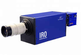


北京欧兰科技发展有限公司为您提供《湍流旋涡火焰中高速OH-PLIF和PIV的同时测量检测方案(CCD相机)》,该方案主要用于其他中高速OH-PLIF和PIV的同时测量检测,参考标准《暂无》,《湍流旋涡火焰中高速OH-PLIF和PIV的同时测量检测方案(CCD相机)》用到的仪器有LaVision IRO 图像增强器、PLIF平面激光诱导荧光火焰燃烧检测系统、德国LaVision PIV/PLIF粒子成像测速场仪、LaVision DaVis 智能成像软件平台。
我要纠错
推荐专场
CCD相机/影像CCD
更多


相关方案
 咨询
咨询