

方案详情文
智能文字提取功能测试中
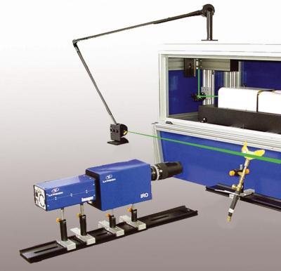
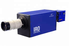
ResearchGateSee discussions, stats, and author profiles for this publicationat: https://www.researchgate.net/publication/225349026 Simultaneous planar measurements of soot structure and velocity fields in aturbulent lifted jet flame at 3 kHz Article in Applied Physics B· May 2011 DOI:10.1007/s00340-011-4549-5·Source: DLR CITATIONS17 READS53 4 authors, including: Markus Kohler Wolfgang MeierGerman Aerospace Center (DLR) German Aerospace Center (DLR)95 PUBLICATIONS 449 CITATIONS415 PUBLICATIONS 5,007 CITATIONS SEE PROFILE SEE PROFILE Some of the authors of this publication are also working on these related projects: M. Kohler, I. Boxx, K.P. Geigle, W. Meier Simultaneous planar measurements of soot structure and velocity fields in aturbulent lifted jet flame at 3-kHz Appl. Phys.B 103 (2011),271-279. Simultaneous planar measurements of soot structure andvelocity fields in a turbulent lifted jet flame at 3-kHz M. Kohler*, I. Boxx, K. P. Geigle, W. Meier Deutsches Zentrum fur Luft- und Raumfahrt (DLR), Institut fir Verbrennungstechnik, Stuttgart *Corresponding author: Dr. Markus Kohler Institut fur Verbrennungstechnik, Deutsches Zentrum fur Luft-und Raumfahrt (DLR), Pfaffenwaldring 38-40 70569 Stuttgart, Germany Phone:++49/711/6862-756 Fax: ++49/711/6862-578 Email:M.Koehler@dlr.de Other authors: Dr. Isaac Boxx Phone:++49/711/6862-732 Fax: ++49/711/6862-578 Email: isaac.boxx@dlr.de Dr. Klaus-Peter Geigle Phone: ++49/711/6862-398 Fax: ++49/711/6862-578 Email: KlausPeter.Geigle@dlr.de Dr. Wolfgang Meier Phone: ++49/711/6862-397 Fax: ++49/711/6862-578 Email: wolfgang.meier@dlr.de Abstract We describe a newly developed combustion diagnostic for the simultaneous planar imaging of sootstructure and velocity fields in a highly sooting, lifted turbulent jet flame at 3000 frames per second, ortwo orders of magnitude faster than “conventional”laser imaging systems. This diagnostic uses shortpulse duration (8 ns), frequency-doubled, diode-pumped solid state (DPSS) lasers to excite laser-induced incandescence (LII) at 3 kHz, which is then imaged onto a high framerate CMOS camera. Asecond (dual-cavity) DPSS laser and CMOS camera form the basis of a particle image velocity (PIV)system used to acquire 2-component velocity field in the flame. The LII response curve (measured in alaminar propane diffusion flame) is presented and the combined diagnostics then applied in a heavilysooting lifted turbulent jet flame. The potential challenges and rewards of application of this combinedimaging technique at high speeds are discussed. 1. Introduction Laser-induced incandescence (LII) is a minimally intrusive diagnostic technique used to study sootstructure and volume fraction in flames and combustion exhaust gases [1,2]. In this technique, sootparticles are rapidly heated to 4000 K (or higher) using a high-intensity pulsed laser. The resultingincandescence is captured on a photo-sensor, typically a photomultiplier tube or intensified CCDcamera. The minimally-intrusive nature of LII, with its ability to take both point and planar in-situmeasurements of soot volume fraction and particle size make it a diagnostic technique of bothfundamental and applied technical interest. It has been used extensively to study soot distributions inflames ranging from laboratory-scale test flames [3,4] to automotive engines [5-7], high-pressureindustrial-type combustors [8-10] and aero engine exhaust [11,12].A thorough review of the theoreticalbasis for the LII technique can be found in [13] and [14]. Soot formation in a turbulent flame is a complex, multi-parameter dependent phenomenon. Studies sofar [15,16] have yielded new insight into the thermo-kinetic processes responsible for soot formation,but all were limited to temporally uncorrelated single-shot measurements. Soot formation and oxidationin a turbulent flame is a transient phenomenon and one highly sensitive to residence time in the flame-zone and local fluid dynamics. An effective way to separate chemical-kinetic (i.e. chemical reactions)and thermo-fluidic (e.g. particle condensation / agglomeration) effects would be to track fluid elementsas they approach, pass through and convect downstream of the reaction zone of a flame and, in effect,perform the measurement in the local frame ofreference of the soot particle itself. Although this isclearly impossible, a practical substitute is to acquire continuous, time-resolved planar measurements ofthe velocity field simultaneously with the LII soot measurement, and track elements as they passthrough the field of view. With the development of high framerate CMOS cameras and high powerdiode-pumped solid state (DPSS) lasers, researchers have recently used simultaneous time-resolved LIFimaging of the hydroxyl (OH) combustion radical and PIV to study transient combustion phenomenaranging from edge-flame propagation [17] to local flame extinction [18], flame hole re-ignition [19],engine misfire [20] and blow-out [21]. Development of a similar flow-tracking capability for LIImeasurements has been hindered however, by the relatively high peak laser fluence (2 mJ/mm’andabove) required to accomplish 2D-LII and the difficulty of performing PIV in a densely sooting flame. The purpose of this paper is to describe a combined LII / PIV measurement system recently developedat the DLR Institute for Combustion Technology, with a 3 kHz framerate and 0.67 second measurementduration, and to present initial results acquired with the system. The kHz-LII system is characterizedand compared to conventional 10 Hz LII systems based on a non-linear LII response curve measured ina laminar propane diffusion flame. Critical limiting factors relating to the kHz LII technique areidentified and discussed. The potential of this advanced combustion diagnostic is demonstrated byapplying it to the study of a heavily sooting turbulent jet flame of ethylene. Sample mean andinstantaneous data from this measurement series is presented and the results compared to data recentlyacquired [22] in the same test flame using conventional LII and PIV measurements. The results indicatethe technique is both viable and yields interesting new insight into the turbulence-chemistry interactionsassociated with soot formation in turbulent flames. Surprisingly, initial results indicate that increasingthe acquisition rate of the PIV measurements from 5 Hz to 3 kHz also simplifies the sooting-flameexperiment and improves measurement quality by significantly reducing the influence of backgroundluminosity. 2. Experimental setup 2.1 Laser-induced incandescence system The LII system consists of a frequency-doubled, Q-switched, diode-pumped solid state (DPSS)Nd:YAG laser (Edgewave IS-8IIE) and an intensified CMOS camera (LaVision, details below), asshown in Fig. 1. At 3 kHz, the laser delivered 5 mJ/pulse at 532 nm, with an 8.5 ns pulse duration. Theshort pulse-duration is essential in order to reach sufficiently high fluence to excite LII using therelatively low energy pulses characteristic of kHz-rate DPSS lasers. A continuously variable beamattenuator consisting of a half wave plate and polarizing beamsplitter cube (for use in measuring the LIIresponse curve) was mounted at the exit of the laser. The beam was formed into a thin sheet using acoatedcylindricallens(fLIl,1 =1000mm)and focusedto a waistusingaspherical 1lens(fu,2=1000 mm). A rectangular aperture was used to block the low fluence edges of the sheet,producing a sheet approximately 6 mm high. The LII laser sheet thickness was measured to beapproximately 500 um at the probe volume using a burn-mark on photographic paper. The spatialprofile of the beam was not measured as no beam profiling camera with sufficiently high framerate wasavailable to image the pulses. Due to the associated uncertainties, we report laser pulse energies insteadof fluence for the remainder of this paper. LII emission was detected perpendicular to the laser beam using a 10-bit, 1024×1024 pixel CMOScamera (LaVision HSS5) with an external two-stage, lens-coupled intensifier (LaVision HS-IRO). Thecamera was equipped with a 100 mm, f/2.8 (Tokina) objective lens. Background flame luminosity wasminimized using a 100 ns intensifier gate. Elastic scattering from soot and/or PIV particles at 532 nmwas blocked using a bandpass filter (LOT 450 FS40-50) centred at = 455±15 nm (FWHM). Thecamera holds sufficient on-board memory (2.6 GB) for 2048 images (i.e., 0.68 seconds continuousimaging) at full resolution. It should be noted that LII signal exists only in the region illuminated by theLII excitation sheet (as defined by the response curve described later) and thus, the imaging array wasnot fully utilized in this experiment. Correction for camera and intensifier sensitivity was accomplishedvia normalization of the measured images with a 2048 frame ensemble average of a uniform white-fieldillumination lamp. As current generation CMOS cameras (particularly those coupled with image intensifiers) are knownto suffer from non-uniformity in pixel response and non-linearity in photon-to-signal conversion [23],the LII data presented below is qualitative and evaluation limited to phenomenological description. Itshould be noted however, that an extensive database of quantitative LII measurements acquired in thesame flame using the conventional (low-framerate) LII technique [22] offers an excellent basis forcomparison and recently developed pixel-by-pixel background characterization techniques [23] offer aviable path to more quantitative measurements in the foreseeable future. 2.2 Particle image velocimetry system The PIV system consists of a Q-switched, dual-cavity DPSS laser (Edgewave, IS-6IIDE) and ahigh-speed CMOS camera (LaVision HSS5). The laser produces 2.6 mJ pulses at 532 nm with pulsedurations of approximately 14 ns at repetition rates up to 10 kHz. In this study the system was operatedat 3 kHz, synchronous with the LII measurement. The laser was formed into a thin, collimated sheetusing three cylindrical lenses (fprv,1=-38 mm, fpIv,2=250 mm, and fpIv,3=750 mm) and overlapped ata shallow angle (<0.6 degree) with the LII excitation sheet. This was accomplished using a mirrormounted sufficiently far (1.9 m) from the measurement volume. As this beam-combining techniqueinevitably results in non-parallel laser sheets, the intersection point of the two beams was set at the mostprobable flame location on the entry-side of the jet-flame (with respect to the laser sheets) and the PIVsheet was made sufficiently thick to ensure good overlap of the measurement volumes in the sooting region on that side of the flame. The resulting PIV laser fluence of 0.02 J/cmor below is not relevant inLII categories and too small to cause particle evaporation. Pulse separation for the PIV system was set to 20 us. The LII excitation pulse was temporallyinterlaced between the first and second PIV pulse of each measurement cycle and timed to occur duringthe inter-frame readout period of the CMOS camera, rendering it invisible to the PIV system. The 10 usdelay between the first PIV pulse and the LII measurement also eliminates the possibility any LII signalexcited by the PIV laser being detected by the LII camera. Mie scattering from titanium dioxide (TiO2) particles (nominal diameter 0.5 um) seeded into the flowwas imaged onto a high speed CMOS camera (LaVision HSS5). The camera was mounted opposite tothe LII camera and was equipped with a 100 mm, f/4 (Tokina) objective lens. Flame luminosity, alreadyminimal compared to conventional PIV cameras due to the short (1/6000* second) integration time ofthe CMOS sensor, was blocked with a 10 nm FWHM band-pass interference filter. The camera isequipped with sufficient on-board memory (2.6 GB) for 2097 image-pairs (i.e., 0.67 seconds imaging)at 768 ×680 pixel resolution. Spatial calibration of the particle images was accomplished using a dual-plane, three dimensional imaging target (LaVision Type 7). Image mapping, calibration, and particlecross-correlations were completed using a commercial, multi-pass adaptive window offset cross-correlation algorithm (LaVision DaVis 7.2). Final window size and overlap were 16 × 16 pixels and50%, corresponding to a vector resolution and spacing of ≈ 0.52 mm and 0.25 mm, respectively.Theparticle images were processed using the extended dynamic range technique described in Boxx et al.[18], wherein vectors derived from the cross-correlation of image pairs in a given measurement cycle(At=20 us) are filtered based on particle displacement and combined with vector fields produced fromcross-correlation of particle images from the subsequent measurement cycle (At =333 us). Based on the±0.1 pixel uncertainty of the cross-correlation peak-finding algorithm, the random uncertainty of thePIV measurements is estimated to be ±0.16 m/s for the inter-pulse separation and ±0.0097 m/s for theintercycle time separation. 2.3 Flames Studied Two flames were used in this study: a laminar propane jet diffusion flame and a lifted turbulent jetflame of ethylene. The former was used to determine the response curve of the kHz-LII system, thelatter to demonstrate its suitability as an applied combustion diagnostic. The laminar flame consisted of a circular (8 mm inner diameter) jet of propane (99.5% purity)issuinginto a concentric, low-velocity co-flow of dry room-temperature air at atmospheric pressure. Propanewas metered into the central tube at a rate of 17.3 g/min via an electromechanical flow control unit(Brooks 5851S) and monitored throughout each experiment using a calibration standard Coriolis massflow meter (Siemens Sitrans-FC Mass-Flo 2100, Model DI-3). The response curve of the LII systemwas derived based on measurements acquired 35 mm downstream of the burner exit, a position wheresoot concentration is almost constant with downstream distance and fluctuations in the radial position ofthe flame were minimal. The lifted turbulent jet flame is based on the test case described recently in [22] and consists of a2 mm diameter round jet of ethylene issuing into a concentric, low-velocity co-flow of dry,room-temperature air. Ethylene (99.95% purity) was metered into the central tube at a rate of 10.4 g/min viaan electromechanical flow control unit (Bronkhorst F1C0-FAC-33-Z) and monitored throughout theexperiment via a calibration-standard Coriolis mass flow meter (Siemens Sitrans-FC Mass-Flo 2100,Model DI-1.5). This corresponds to a bulk flow-velocity of 44 m/s at the jet-exit, and jet-exit Reynoldsnumber of 10000. The resulting flame is lifted and has a visible flame length of 400-500 mm. For thedemonstration of the technique, two imaging regions were used: the first spanning 58 -68 mm and thesecond 98 - 108 mm downstream of the jet-exit. Extinction measurementsby previous researchers [[22] indicate the average maximum ssootconcentration in this flame is 0.54 ppm and instantaneous soot concentrations can exceed 5 ppm. 3. Results and Discussion 3.1 High-speed LII The correct interpretation of LII data depends on knowing the response characteristics of themeasurement system to a given excitation laser fluence. This is typically determined by measuring aresponse curve of the system in a well-defined sooting flame. Conventional LII imaging systems areusually operated in the so-called ‘plateau region’of the response curve [13,24]. In this region theintegrated LII signal measured by the detector becomes almost independent of the fluence of theexcitation laser. Figure 2 shows the response curve for the LII system, measured in the laminar propane diffusionflame described above. It was measured by taking 1000-shot LII image sequences of the flame overexcitation energies ranging from 0 to 5 mJ/pulse. The ensemble-average of LII signal, integrated over the sooting regions of the flame (shown by the boxes on the representative mean-image) is used as amarker for LII response. As the sheet profile was seen to be inhomogeneous in the vertical direction, itwas impossible to define a single, global fluence for the LII system. Instead, three integration windowsizes were used and the results compared for consistency.As beam-steering, laser attenuation and sheetdivergence may affect the excitation laser as it propagates through the flame the response curve wasmeasured on both the laser entrance and the laser exit side of the laminar flame. Finally, as LII responsecurves are known to be highly dependent on laser-sheet profile and collection optics configuration [25],the measurement was made with the optics, camera settings and intensifier gate identical to that used toimage the sooting turbulent jet flame. As can be seen in Fig. 2, the results were uniformly consistent.All measured LII response curves increase in a quasi-linear fashion up to pulse-energy 1.7 mJ, afterwhich the integrated signal plateaus and subsequently only minor changes are observed with increasingexcitation energy. Similar behaviour (not shown here) is found for very small evaluation rectangles (3x3pixels). Deterioration of the excitation beam profile quality is the most probable explanation fordifferent signal levels in the response curves. For the turbulent flame characterized below, only the laserentrance of side of the soot distribution was overlapped with the PIV field of view. Figure 3 shows a sequence of LII images acquired in the sooting turbulent jet flame at 3 kHz. Toillustrate the signal-to-noise ratio and image quality achievable with the system, the images in Fig. 3 arenot corrected for noise, camera sensitivity or laser sheet profile. Despite this, soot structures are clearlyidentifiable and well resolved across the width of the flame and can be easily tracked from one frame tothe next. A comparison of the images in Fig. 3 with those acquired in the same flame and imaginglocation with a conventional LII system [22] shows soot structures of very similar size and shape, aqualitative indication of similar detection sensitivity, albeit over a smaller imaging region. Figure 3 illustrates that individual soot structures can be identified and tracked from frame-to-frame.Remarkably, a significant influence of the laser radiation on the soot distribution or LII signal reductionis not observed. This gives rise to the question whether individual soot particles have been subject tomultiple excitations and possibly a significant change in the soot characteristics. PIV measurementsdescribed below indicate that multiple excitations are likely. For example, at h~ 100 mm and r~ 10 mmwhere high soot concentrations are observed in Fig.3, the mean axial velocity is on the order of 2 m/s(see Fig.5b). Thus, from shot to shot (0.333 ms) the fluid is convected on the average by about 0.7 mmin axial direction. At r~ 8 mm it is about twice the distance. The instantaneous out-of-plane velocity(circumferential velocity component) was not determined in this study. However, it is expected to be significantly smaller than the axial velocity so that a fluid element probably stays within the laser sheetof 0.5 mm thickness for several shots. This estimation indicates that individual soot clouds are probablysubject to several laser shot exposures. It is well established [26] that even at relatively low laserfluences (ca. 1.5 mJ/mm), LII excitation can have measurable effects on soot morphology. Recent work[27] has shown that these effects extend to the optical properties of the soot, indicating that multipleexposures of the same soot particle may result in a spurious measurement. This effect was not accountedfor in the present measurements and is beyond the scope of this paper. We note, however, the peak laserfluence used for LII in this study is not far beyond that shown to induce initial changes in sootproperties, and significant effects of multiple exposures were not observed in our image sequences. A further point should be kept firmly in mind in studying image sequences of this sort; that soot is nota conserved scalar and it is impossible to determine with certainty the origin of soot appearing in a givenregion of an LII image, or where it goes when it disappears. It may form in-plane through chemicalreaction or simply convect into the measurement plane through bulk fluid motion. Soot disappearingfrom the field of view may have been oxidized, de-agglomerated and dispersed by fluid-dynamic shearstress or have propagated out of the plane of laser excitation. Stereoscopic PIV provides a means toidentify regions where through-plane convection is a possible explanation, but even then does notanswer the question with certainty. Thus, special care must be taken in drawing global conclusionsbased on planar measurements such as these. 3.2 Highspeed PIV Figure 4 shows two pairs of unprocessed (raw) particle images acquired in the sooting turbulent jetflame alongside a pair of images taken in the flame using a conventional 5 Hz system to illustrate asomewhat surprising practical advantage of the kHz-PIV technique over its conventional low-frameratecounterpart. Both image pairs show luminous soot structures as well as the Mie scattering from the seedparticles. While the images recorded with the high-speed system exhibit similar signal quality, thesecond image obtained with the 5 Hz system is dominated by luminous soot or flame structures. The overwhelmingly dominant imaging technology used in conventional PIV systems is the interline-transfer CCD camera. These cameras capture two images in rapid succession by exposing a CCDimaging array, rapidly transferring the resulting charge into an array of on-sensor storage registers andimmediately beginning the exposure of the second frame, thus allowing the sensor to capture a secondframe before the first is completely read out. Although this allows two frames to be acquired in rapid succession it has a major drawback when used in highly luminous sooting flames, namely significantdifferent exposure times for first and second image. Whereas the first frame may have a sub-microsecond exposure time, the second frame may be exposed as long as 30 milliseconds or more,resulting in perhaps orders of magnitude greater soot luminosity being acquired in the second frame. Asthe PIV technique relies on the cross-correlation of two particle images, this makes it challenging toobtain reliable vector yields. CMOS cameras however, do not have this problem inasmuch as they runcontinuously at double the framerate of the pulsed laser source, capturing each laser pulse on separate,equally exposed frames. Although some soot luminosity is still captured during each exposure, the equalexposure time serves to minimize its effect on the PIV cross-correlation function. In addition, theabsolute exposure time of the PIV image is one over twice the framerate, meaning the higher theframerate, the lower the exposure time and the less soot luminosity acquired in a given image. Althoughit is clearly possible to mitigate some of the problems associated with different exposure timescharacteristic of interline transfer CCD cameras, for example with narrower bandpass filters, smallerimaging apertures, larger PIV interrogation windows or more exotic shuttering techniques, each methoddegrades the overall system performance in its own way. The short, constant exposure periodscharacteristic of highspeed CMOS cameras eliminates the problem altogether, thus making them moresuitable for PIV in highly luminous sooting flames. Figure 5a shows the ensemble-averaged velocity field measurements for each of the two regionsmeasured in the sooting turbulent jet flame with the highspeed LII/PIV system, together with the meanvelocity field measured by Kohler et al. [22] using conventional 5 Hz PIV. Figure 5b shows horizontalprofiles at 60 and 100 mm height above the burner exit for each of the datasets for comparison. We notean apparent misalignment of the 5 Hz data inasmuch as the peak velocity in that profile occurs slightlyto the right of the centerline. If one corrects for this misalignment, the overlap in the profiles is evenbetter at both locations showing a good agreement. The kHz-rate PIV measurements show smoothermean contours, indicative of more fully converged mean data. This results from our having used 2096PIV measurements at 3 kHz to compute the mean velocity field shown, compared to 200 PIVmeasurements at 5 Hz used by Kohler et al. [22]. Figure 5 also shows the significantly higher spatialresolution of the kHz-PIV measurements compared to the 5 Hz measurements [22]. Although the choiceof PIV resolution in the present work was driven by a desire to match the field of view of the LIIsystem, it is clear from the sample LII/PIV sequence of Fig. 6, it resulted in an excellent match to thelength scales of the temporally developing soot structures at the measurement location. 3.3 Simultaneous high-speed LII and PIV Figure 6 shows every second frame of a representative LII / PIV measurement sequence acquired withthis system in the sooting turbulent jet flame. The PIV imaging region spans 98 -108 mm downstreamof the jet-exit. The mean velocity field at this location has been subtracted from the instantaneous vectorplots to better isolate and identify fluid-dynamic effects in the frame of reference of the soot structures.Although a detailed analysis of the spatiotemporal interaction of soot structures and the local flowfieldis clearly beyond the scope of this work, some interesting phenomena are observable in Fig. 6. In thissequence, we see a soot structure spanning approximately half the jet-width propagate through the fieldof view of the measurement system, deforming as it interacts with higher velocity fluid near the jet-centerline. In frame 1, the downstream edge of the structure is thin and resides in the periphery of the jetat a radial position of approximately 10 mm. By frame 3, the downstream edge of the structure hasmoved beyond the field of view and the structure is seen to have widened considerably and now spansall the way from the centerline to the outer periphery of the jet. In frame 4, as the trailing edge of thestructure propagates up through the field of view we see it begin to deform, with the portion closer tothe high-velocity centerline swept downstream faster than that laying in the periphery. By frame 5, onlya small portion of the trailing edge of the structure remains visible in the image. Despite the LII data in the present work being non-quantitative, comparison of the data in Fig. 6 withprevious measurements in the same flame yield a logical explanation of what we see in this imagesequence. Comparing the spatial location of the soot filament in frame 1 with the mean velocity fieldsshown in Fig.5, it is clear the structure resides at the outer edge of the fuel jet. Comparison withpreviously published OH* chemiluminescence data [22], one sees this soot structure also resides veryclose to the mean reaction zone location. Absent a direct measurement of the instantaneous reactionzone location (e.g. via LIF imaging of CH or OH) it is impossible to say with certainty, but it is highlyprobably the soot structure in frame 1 is enveloped by a high velocity fuel flow on the left side and areaction zone on the right. It iswell established [28] that shear affects soot formationl andagglomeration, and one would expect rapid oxidation and burnout of soot in the reaction zone, resultingin a thin, filament or sheet-like soot structure there. Comparing the LII images with the instantaneousflowfields in frames 2 and 3, we observe that a.) the structures become significantly wider near the jetcenterline and b.) the structures reside in a region of the flow that, in the local frame of referenceresulting from having subtracted the mean velocity field, resembles the region immediately upstream of a stagnation-point. Thus, in the moving reference frame of the fluid element, the thickest part of the sootstructure exists in a low-velocity region where residence times are longer and fluid-dynamic extensivestrain is minimal. Finally, the thickest point of the soot structure also exists closer to the centerline,where one would expect to find little oxygen to burn out the soot. In frame 4, the soot structure isaligned with the local stagnation point flow and has begun to thin. By frame 5, the bulk of the structureis beyond the field of view. Taken together, a reasonable explanation of this sequence is that the sootformation here is being driven by a large-scale vortex structure propagating up through the jet, with theuppermost edge impinging upon the reaction zone and its wake inducing a region conducive to sootformation. Although this result is unsurprising, for it is known that regions of low strain, high fuelconcentration and long residence time are conducive to soot formation, Fig. 6 is illustrative of the powerof simultaneous highspeed LII and PIV imaging. With access to both the temporally developing sootand velocity field information, a greater fundamental understanding of the turbulence-chemistryinteraction responsible for soot formation and reduction is possible. Conclusion Simultaneous planar laser induced incandescence (LII) and particle image velocity (PIV) measurementshave been performed in a sooting turbulent jet diffusion flame at a sustained repetition rate of 3 kHzemploying diode pumped solid state lasers. Using a pulse energy of 5 mJ at 532 nm with a pulseduration of 8.5 ns, high quality LII images were achieved in a sheet of 6 mm height. The soot structurescan be tracked from frame-to-frame reflecting the temporal development of the soot distribution. Thequestion whether distinct soot particles were subject to multiple LII laser light exposures can not beanswered unambiguously, but simultaneous acquired velocimetry data indicates it is likely. Importantly,the LII images show no indication ofchanges of the size or morphology of soot particles as a result ofthis. High-speed PIV mmeeaassurementswere performed using TiO2 seed particles of 0.5i um diameter.Compared to “classical”PIV measurements with interline transfer CCD cameras, the current setup witha high-speed CMOS camera resulted in a high signal-to-background ratio and thus better image qualityfor the second frame of a PIV image pair. The reason is a significantly reduced exposure time for thesecond frame by which the background from flame luminosity is strongly suppressed. In this way, highquality PIV measurements were performed despite the luminous soot radiation. The simultaneousapplication of LII and PIV at 3 kHz enables a deeper insight into the interaction between the flow-field and the soot structures. In an example sequence it is demonstrated that high soot concentrations arecorrelated with low relative flow velocities (long residence time) and low extensive strain. The results obtained in this sooting turbulent C2H4 jet flame show that a combined LII/PIV measuringsystem is able to generate high-quality results at repetition rates that enable the tracking of temporaldevelopment. It thus has the potential to significantly extend the understanding of soot formation andoxidation phenomena in combustion systems of fundamental and applied technical interest. Acknowledgements The authors wish to thank Brian Crosland for helpful discussions and Dr. Campbell Carter of the AirForce Research Laboratory for providing the co-flow burner used in this study. ( References ) ( [1] A.C. E c kbreth, J. Appl. Phys. 4 8, 4473-4479 (1977) ) ( [2] L.A. Melton, Appl. Opt. 23, 2201-2208 (1984) ) ( 3 ] C.R. Shaddix,K. Smyth, Combust. Flame 107,418-452(1996) ) [4]S. Will, S. Schraml, A. Leipertz, Proc. Combust. Inst. 26,2277-2284(1996) [5]J.E. Dec, A.O. zur Loye, D.L. Siebers, SAE Technical paper 910224 (1991) ( [6] B. Bougie, L .C. Ganippa, A .P. v an Vliet, W.L. Meerts, N.J. D am, J . J. ter Meulen, Combust.Flame 1 45, 635-637 (2006) ) ( 7 B.F. Kock, B. Tribalet, C. Schulz, P. Roth, Combust. Flame 147, 7 9-92(2006) ) ( 81 M . Braun-Unkhoff, A. Chrysostomou, P. Fr a nk, E. Gu t heil, R . Liickerath, W . Stricker, Proc. Combust. Inst.27 , 1565-1572(1998) ) ( 9] M.Hofmann, W.G. Bessler, C. Schulz, H. Jander,Appl.Opt. 42, 2052-2062(2003) ) ( [10] O. Lammel, K.P. Geigle,R. Liickerath, W. Meier, M. Aigner, Proc. ASME Turbo Expo 2007,Power for Land, Sea and Air, 14.-17.05.2007, Montreal (Canada), Paper GT2007-27902 ) [11] R. Snelling, G. J. Smallwood, R. A. Sawchuk, W. S. Neill, D. Gareau, D. J. Clavel, W. L. ( Chippior, F. Liu, O. L. Gulder , SAE Tech. Paper 2000-01-1994 (Society o f Automotive Engineers, Warrendale, Pa., 2000) ) ( [12] J.D. Black, M.P. Johnson, Aerosp. Sci . Technol . 14,329-337(2010) ) ( [ 1 3] R.J. Santoro, C.R . Shaddix,“Laser-induced incandescence” . I n Kohse-Hoinghaus K., andJeffries J. (Eds.) Applied Combustion Diagnostics, Taylor and Francis, London (2002) ) ( [ 1 4] C. Schulz, B.F. Kock, M . Hofmann, H. Michelsen, S. Will, B . Bougie, R. Suntz, G. Smallwood,Appl. Phys. B, 83,333-354 (2006) ) ( [15] S.-Y. Lee, S.R. Turns, R.J. Santoro, Combust. Flame 156, 2264-2275(2009) ) ( [16] Q .N. Chan, P.R. Medwell, P.A.M. Kalt, Z.T. Alwahabi, B.B. Dally, G.J. Nathan, Proc. Combust.Inst. 33,791-798(2011) ) ( [17] C . H eeger, B . B ohm, S.F. A h med, R. Gordon, I. B oxx, W. M eier, A. Dreizler, E. M astorakos,Proc. Combust. Inst. 32, 2957-2964 ( 2009) ) ( [18]I . B oxx, M. Stohr, C . Carter, W. Meier, Appl. Phys. B 95, 23-29 (2009) ) ( [19] A.M. Steinberg, I . Boxx, C. Arndt, J.H. Frank, W. Meier, Proc. Combust. Inst. 33 , 1663-1672 (2011) ) ( [20] C .M. Fajardo, V. Sick, SAE Paper 2009-01-0651 (2009) ) ( [21] M . Stohr, I . Boxx, C . Carter, W. Meier, Proc. Combust. Inst. 33,2953-2960 (2011) ) ( [22] M . K ohler, K .P. Geigle, W. Meier, B.M. Crosland, K.A. Thomson, G.J. S mallwood,Appl. Phys B,(2011), DOI: 10.1007/s00340-011-4373-y(2010) ) ( [23] V . W eber, J. Bribach,R . L. Gordon, A. Dreizler, Appl. P hys. B R eview (2010) ) ( [24] P .O. Witze, S. H ochgreb, D. Kayes, H. A . Michelsen, C.R. Shaddix, Appl. Opt. 40, 2443 - 2452 (2001) ) ( [25] H . B ladh, P.E. Bengtsson, Appl. Phys. B 78, 241-248 (2004) ) ( [26] R .L. Vander Wal, T.M. Ticich, A.B. Stephens, Appl. Phys. B 67, 115 - 123 (1998) ) ( [27] K. T homson, K.P. Geigle,M. Kohler, G.J . Smallwood, D.R. Snelling, Appl. Phys. B, ( 2 01 1 ), DOI 1 0.1007/s00340-011-4449-8 ) ( [28] M . E. D ecroix, W. L . Roberts, Combust. Sci. Technol. 160, 1 65-189(2000) ) List of Figures Figure 1: Setup for the combined LII/PIV experiment running at 3 kHz on a lifted turbulent jet flame. Figure 2: LII signal as a function of energy. The averaged intensity in three regions is used to observeinhomogeneities in the used laser sheet for the laser entrance side or laser exit side. The imageindicating the analysed rectangles is an average of 1000 single shots excited at 4.7 mJ. 0 2 3 4 5 Energy[mJ] 3 kHz. An excitation pulse energy of 4.7mJ is chosen for all soot concentration imaging measurements. 19 Figure 4: Comparison of raw particle images in the sooting turbulent jet flame; a,b) image pair for 3kHz PIV andc,d) image pair for conventional 5 Hz system. a)3 kHz - Frame 1 b) 3 kHz-Frame 2 c) 5 Hz-Frame 1 d) 5 Hz-Frame 2 Figure : Comparison of high-speed (3 kHz) and conventional (5 Hz, [22]) PIV measurements in thesooting ethylene/air jet flame. a) Comparison of velocity contour plot from 5 Hz measurement (left) and3 kHz measurement (right). b) Horizontal velocity profiles for selected heights at HAB= 60 mm and100 mm. a) Radial distance r [mm] b) Radial distance r [mm] Figure 6: Sample measurement sequence of simultaneous 3 kHz PIV/LII for the sooting ethylene/air jetflame. 10 m/s 0.67 ms 10 m/s 0 ms All content following this page was uploaded by Wolfgang Meier on March The user has requested enhancement of the downloaded file. We describe a newly developed combustion diagnostic for the simultaneous planar imaging of soot structure and velocity fields in a highly sooting, lifted turbulent jet flame at 3000 frames per second, or two orders of magnitude faster than “conventional” laser imaging systems. This diagnostic uses short pulse duration (8 ns), frequency-doubled, diode-pumped solid state (DPSS) lasers to excite laserinduced incandescence (LII) at 3 kHz, which is then imaged onto a high framerate CMOS camera. A second (dual-cavity) DPSS laser and CMOS camera form the basis of a particle image velocity (PIV) system used to acquire 2-component velocity field in the flame. The LII response curve (measured in a laminar propane diffusion flame) is presented and the combined diagnostics then applied in a heavily sooting lifted turbulent jet flame. The potential challenges and rewards of application of this combinedimaging technique at high speeds are discussed.
关闭-
1/24

-
2/24

还剩22页未读,是否继续阅读?
继续免费阅读全文产品配置单


北京欧兰科技发展有限公司为您提供《湍流举升射流火焰中平面碳烟结构和速度场检测方案(粒子图像测速)》,该方案主要用于其他中平面碳烟结构和速度场检测,参考标准《暂无》,《湍流举升射流火焰中平面碳烟结构和速度场检测方案(粒子图像测速)》用到的仪器有德国LaVision PIV/PLIF粒子成像测速场仪、PLIF平面激光诱导荧光火焰燃烧检测系统、激光诱导白炽光烟雾粒子成像分析仪(LII)、LaVision IRO 图像增强器、LaVision DaVis 智能成像软件平台。
我要纠错


相关方案
 咨询
咨询