方案详情文
智能文字提取功能测试中
ResearchGateSee discussions, stats, and author profiles for this publication at: https://www.researchgate.net/publication/251297819 Experimental Mechanics (2012) 52:417-428DOI 10.1007/s11340-011-9502-3 Micron-Scale Residual Stress Measurement bvMicro-Hole Drilling and Digital ImageCorrelation Article in Experimental Mechanics · April 2012DOI: 10.1007/s11340-011-9502-3 CITATIONS18 READS 210 2 authors: Bart WiniarskiThe University of Manchester Philip J. WithersThe University of Manchester 44 PUBLICATIONS 218 CITATIONS 718 PUBLICATIONS 10,989 CITATIONS SEE PROFILE SEE PROFILE Some of the authors of this publication are also working on these related projects: Nano and micro-CT investigation of Mg and Mg based alloys, focussing on impurity and intermetallicinfluence on corrosion/electrochemical behaviours View project All content following this page was uploaded by Philip J. Withers on 23 December 2016. The user has requested enhancement of the downloaded file. All in-text references underlined in blue are added to the original documentand are linked to publications on ResearchGate, letting you access and read them immediately. Micron-Scale Residual Stress Measurement by Micro-HoleDrilling and Digital Image Correlation B. Winiarski·P.J. Withers Abstract This paper reports a new technique, namely theincremental micro-hole-drilling method (IuHD) for map-ping in-plane residual or applied stresses incrementallyas a function of depth at the micron-scale laterally andthe sub-micronscale depth-wise. Analogous to itsmacroscale counterpart, it is applicable either to crystal-line or amorphous materials, but at the sub-micron scaleOur method involves micro-hole milling using thefocused ion beam (FIB) of a dual beam FEGSEM/FIBmicroscope. The resulting surface displacementsarerecorded by digital image correlation of SEM imagesrecordeddduring milling. The displacementffieldsrecorded around the hole are used to reconstruct thestress profile as a function of depth. In this way residualstresses have been characterized around a drilled hole of1.8microns. diameter, enabling the profiling of the stressvariation at the sub-micron scale to a depth of 1.8 microns.The new method is used to determine the near surface stressesin a (peened) surface-severe-plastically-deformed (S’PD)Zr50Cu40Alio (in atomic percent, at.%) bulk metallic glassbar. In plane principal stresses of -800 MPa ± 90 MPa and-600 MPa ± 90 MPa were measured, the maximumcompressive stress being oriented 15° to the axis of the bar. Keywords Scanning electron microscopy (SEM)·Residualstress·2D digital image correlation· Surface decorationmethods·Incremental centre hole drilling B. Winiarski (区, SEM member)· P.J. Withers (SEM member)School of Materials, Materials Science Centre,The University of Manchester,Grosvenor Street.Manchester M1 7HS, UK. e-mail: b.winiarski@manchester.ac.uk Residual stresses arise in most materials as a consequenceof processing and/or in-service loading. Depending on theirsign, magnitude, spatial distribution, and the scale overwhich they equilibrate, residual stresses can alter themechanical and functional performance [1]. Consequentlytheir quantification is of great importance across manysectors. Whilst there exists a plethora of techniques formeasuring stress at the macroscale, few techniques allowmicron scale evaluation, either laterally or with depth,especially for amorphous materials In theory, destructive and semi-destructive techniquesbased on mechanical relaxation phenomena, such as slitting[2, 3], hole/core drilling [4-11] and curvature methods [12]can be scaled down and applied to smaller structures [13-25] than those to which they have traditionally beenapplied. The advent of dual beam focused ion beam-fieldemission gun scanning electron microscopes (FIB-FEG-SEM) has, in combination with digital image correlation(DIC) analysis, made it possible to make very fine excisionsand to record the resulting displacements with high precision,usually in the nanometre range. Recently, this has led to anumber of micro-scale analogues of the mechanical stressmeasurement methods. For example, 0.28 um deep 10×0.2 um slots have been used to measure the stresses in anamorphous diamond-like carbon coating [14], while stresseshave been mapped at the micron scale in bulk metallicglasses using an array of such slots [20]. This methodprovides a measure of the stress normal to the slot averagedover the slot depth. Depth profiling has been achieved bymonitoring beam deflection of micro-cantilevers as they areprogressively milled [25]. However, for stress mapping itrequires excavation of large micro-cantilevers (length of100 um or more). Essentially both methods are based on 1-D analyses, allowing only a single component of stress to bedetermined, with lateral spatial resolutions of many tens ofmicrons. Other examples show that atomic force microscopy(AFM) in combination with DIC is capable of surfacedisplacement field measurement in the nanometre range.This measurement method together with the microscopicthrough-hole method has been successfully applied to assessstresses and elastic properties of polycrystalline silicon microelectro-mechanical system (MEMS) devices [19]. the residual-stresses profiles in a surface-severe-plastically-deformed bulk metallic glass (BMG) system to a depthresolution of ~200 nm and a lateral resolution of around10 um based on a 4 um micro-hole. Materials and Methods Sample Preparation The Zr-based Zr5oCu40Al10 (atm%) BMG was preparedby arc-melting a mixture of pure zirconium, copper, andaluminum melts (purity better then 99.9% by weight) in anargon atmosphere. A tilt-casting method was implementedto cast the alloy to its final rod shape of 60 mm anddiameter of 8 mm. The rod sample was cut to a rectangularbar of 3×3×25mm’and, then, polished using the 600-gritgrinding paper. Subsequently, one side of the specimen was repeatedlybombarded in an argon atmosphere with twenty WC/Coballs, each having a diameter of 1.6 mm, using a Spex 8000miller in a back-to-force mode with a frequency of 60 Hz.The bombardment process lasted for 180 minutes pausingevery 15 minutes. This surface-severe-plastic-deformation(S’PD) process has a much higher average impact energythan the shot-peening process, thereby generating aseverely-deformed near-surface layer of thickness about180 um in the BMG at room temperature, constrained byan elastically deformed region immediately below this. Thenear-surface layer which is about 30-40 um thick with aneffective plastic deformation of about 10%-30%, contains auniform distribution of sub-micron size shear bands (see[34] and references cited there). The near surface stressvariation has been previously determined by micro-slotting andis similar to that characteristic of shot-peening profiles [20].The peak compressive residual-stress is located within themicrostructurally-affected layer at a depth of around 160 um. To enhance the accuracy of the DIC analysis, the specimensurface was decorated with 20-30 nm yttria-stabilized-zirconia(YSZ) equi-axed particles precipitated from an ethanolsuspension (see Fig. 1), where the surface coverage is about10%. To minimize any surface charging effects and to"protect’the surface from Ga implantation, the surface ofthe specimen was coated with a22 nm thick carbon film usinga Gatan PECS 682 etching-coating system equipped with aGatan 681.20000 Thickness Meter. This decoration techniqueallowed us to work at magnifications of 10,000x in FEGSEMmode viewing a surface area of tens of square microns [30]. Experimental Procedure The two requirements for accurate DIC measurements ofsurface deformations are the presence of a fine and high- Fig. 1 (colour online) FEGSEM image of the microhole of diameterd=4.0±0.07 um and depth, z=1.8±0.07 um; the surface has beendecorated with YSZ nano-particles and then carbon coated contrast surface texture, and the use of large correlationpatch sizes [28,35]. However, the imaging conditions used,namely voltage, current, dwell time, detection of secondaryelectrons (SE) or back-scattered electrons (BE), secondaryions (SI), digital image resolution, etc., are also important[36.37]. A series of FEGSEM imaging trials was performed toidentify the optimal imaging conditions for DIC analysis.The control parameter chosen for minimization was theuncertainty of the DIC displacement (standard deviation ofthe displacement (SD,) mapped over the whole imagingarea (here 1015 data points). It was found that an electronbeam (e-beam) acceleration voltage of 5 kV, with beamcurrent 0.40 nA, and detection of secondary electrons givesgood contrast images with negligible charging of thesample surface. Subsequently, a range of e-beam dwelltimes (D;) (D, of 1 us, 3 ps, 10 us and 30 us) and imageacquisition conditions (image integration over 1, 4,8 and16 frames) were analyzed. All images were acquired afteran auto-brightness/auto-contrast procedure. It was foundthat an e-beam dwell time of 3 ps and an integration over8 frames (total image acquisition time =21.7 s) gave thelowest SDu (~0.0147 pixel) for DIC patches of 64×64pixels overlapped by 75%. An inherent feature of the FIB-milling process ismaterial redeposition such that the milled walls are notperfectly rectangular, especially when milling deep holes ornarrow slits. To limit such effects, the FIB-milled holeshould be shallow. A diameter to depth ratio less than one iswell matched to the inherent limitations associated withhole-milling experiments, whereby the magnitude of the surface relaxations plateau as the contributions of stressesreleased at greater depths decline rapidly with the holedepth. In order to map the stress profile in a severelyplastically peen deformed BMG, we have introduced amicro-hole of 2 um radius to a depth of 1.8 um (see Fig. 1)in 10 depth increments. This was achieved using a focusedGa ion beam of 0.28 nA accelerated by an electric field of30 kV. The hole-irradiation process was done at a 52°angle, where the sample surface is normal to the ion columnaxis. The surface displacements due to the stress relaxationswere mapped by cross-correlation from the FEGSEMimages (these are of much higher quality and do littlebeam damage compared to Ion Beam images) at eachincrement using DIC software (LaVision DaVis 7.2) [seeFig.2(a)]. Each image was taken after tilting the samplestage to the 0° position. The first FEGSEM image wastaken for the imaged region without the hole, and was usedas the reference image for the cross-correlation analysis.The DIC patches (64×64 pixels overlapped by 75%)covered the whole imaged area apart from the micro-holeand its immediate vicinity (within 0.7 um), where someexcavated material is redeposited. This area experiences thelargest surface displacements, however the sputtered mate-rial significantly alters the surface contrast [see Fig. 2(a)]making DIC analysis unreliable there. Since the amplitudeof the surface displacements decline rapidly from the holeedge, only the region for which the signal-to-noise ratio islarger then 5 is taken into consideration. Accordingly, theanalyzed region is bounded by inner and outer radii ri=2.78 um (rori=0.7) and r2=4.75 um (ror2=0.4) as shownin Fig. 2(b) where the maximum principal strains in radialdirections are mapped. It is evident from the surfacedisplacements [Fig. 2(c), (d)] that the state of in-planecompressive stress (since the displacements tend to closethe hole) in the vicinity of the micro-hole is non-uniformand varies harmonically around the hole. The largestcompressive stress acts approximately along the sample(x direction). Subsequently we show how these mappeddisplacements can be converted into stress profiles. Stress Reconstruction Method The analytical solution for the stress-strain state of acylindrical hole in an isotropic material, where the stressesan, ar and angle o are the unknowns, was given byMuskhelishvili, who used the potential function of thecomplex method [38]. Following an argument in [6], thethree unknowns (x,a, and oxy) can be determined fromequation (1) using three values of the relieved displace-ments (U, Un and Um), each measured between twopoints, which are determined at the intersection of a circleof radius r> ro and a line crossing the centre of the hole, 270 Micro-hole depth, z [um] Fig. 2 (colour online) Digital image correlation analysis results for the final increment, z=1.8±0.07 um: (a) 2-D displacement vector field(vectors are exaggerated by ×15); (b) 2-D map of the maximum principal strains; (C) radial displacements, u, vs. angle, o, measured at distancero/r=0.5; (d) radial displacements, ur, vs. hole depth, z, measured at distance ror=0.5 and angles, 0=0°, 45°, 90° and 135° where the three lines are positioned at 0=0°, 45° and 90°[see Fig. 2(b)]. Digital image correlation data allows us to measure up toseveral hundred data points, therefore the calculation can berepeated for a number of radial (ro/r=0.6, 0.5 and 0.45) andangular (0°<0+0<180°,A0=5°) positions. Thus relieveddisplacements can be expressed compactly in matrix form interms of radial and angular coordinates, as follows (1) where U= 2u2u00+0+)0), Un= 2u45+0'),, Uum 2u90+0)Stresses ox(0), ay(0) and txy(0) are calculated in localrectangular coordinates rotated degrees in the anti-clockwise direction (see Fig. 1). Coefficients A and B arethe cumulative stress relaxation functions (CRFs) (for equi-biaxial and pure shear states of stress) either obtained byFEA, or from an experiment where a micro-hole is ion-milled into material with known residual stresses. Separatefinite element calculations are required for the coefficientsA and B for various combinations of hole depth and stresslocation. A superposition argument [5] allowed us to calculatethe calibration coefficients in a linear-elastic-isotropicmaterial (E=95±GPa, and v=0.37 [39]) directly usingloadings where the reference residual stresses, for which ( 1 Abaqus 6 . 8 package was used. 2 ) ( A s a metallic glass the assumption of i sotropy at this le n gth-scale is e asily justified. ) associated deformations have simple trigonometric forms,3are applied with opposite sign to the curved surface of themicro-hole [6]. The remaining surfaces of the FE modelswere unstressed. Our FE model was assembled using 8-node (quadratic approximation function) square-shapeaxisymmetric elements where the size of elements in thevicinity" of the hole was 1/30th the hole diameter, seeFig.3. In order to make the coefficients independent of the holediameter and the elastic constants, it is useful to convert theCRFs into dimensionless cumulative stress relaxationfunctions (DCRFs); The DCRFs A(r) and B(r) are tabulated in the Appendix for a number of radial locations (ror=0.6, 0.5 and 0.45).Fig. 4 shows a graphical representation of the DCRFs for thehole radius ror=0.50. Both functions are well-behaved overthe range plotted, indeed no singularities exist over thepractical range of hole depths. In practice, the hole depthshould be equal or smaller than the hole radius [5]. For largerhole depths the residual stress solution is ill-conditioned,resulting in large uncertainties in the stress estimates.Bothfunctions have a shape similar to those in [5]. In general, each micro-hole-drilling measurement willcomprise an irregularly spaced series of hole depth incre-ments. The DCRFs corresponding to these specific holedepths may be determined by interpolating within the set ofvalues found by the finite-element analyses and tabulated inthe Appendix most easily by using the bivariate interpola-tion scheme, as described there. Adjustments for smallchanges in the hole radius can be made, since the DCRFsfor given normalized hole-depth and stress position are verynearly proportional to the square of the hole radius (seedetails in [5]). Equations in matrix form (1) are solved simultaneouslyfor the residual stresses. By transforming the measuredstresses into the global coordinates: sino from the mean stresses (r, o,, ty) acting in the directions ( ' Asymmetric ze r oth-harmonic radial displacement (f o r coefficient A)and symmetric second-harmonic radial and circumferential displace- ment ( for coefficient B). ) ( "The vicinity o f the hole is e q ual 6x th e ho l e diameter in rad i al and h ole d epth directions. ) x and y (see Fig. 1). We can extend the methodologypresented above to reconstruct the residual-stress depthprofiles using the Unit Pulse Method [4. 5]. Equation (1)relates the measured displacements, U, to the equivalentuniform in-plane residual stress in the first depth-increment.Generalizing to k depth-increments we obtain 0 100 p(1)T(1)p(2)g(2)p(2)p(i)g)T(i) :u)uu0j (5) in compact form where, to be concise we omitted the r,o dependencies, e.g.Urepresents U(r,0). U is a vector of the displacementsmeasured by DIC when the hole-depth is h; II is a vectorof the uniform stress terms P,",T acting in stresslayer AH, lying between depths H-i and H; and O(hi,AH) is a matrix of the incremental calibration functions(ICFs) relating the relieved displacements to the uniformstress terms acting at depth H; when the hole depth equalsh;. Following arguments in [5] and if we know the CRFsobtained from FEA, the ICFs can be determined easily forany number and size of hole-depth increments by simplesubtractions. We can obtain the desired solution of thestress variation with depth by inverting equation (6). Weobtained a tentative solution (the linear operator equations)to equation (6) using pseudo-inversion. The three unknownstresses (0x, oy and txy) for each hole-increment can then beestimated by the mean stresses (x, oy and txy) acting inthe directions x and y using similar relationships toequations (2) and (4). Regularisation In practice measured data are a convolution of measurementnoise and the “true’values. The pseudo-inversion algorithmyields stable residual stress solutions if the coefficients of Fig. 3 Axisymmetric FE modelfor a hole of depth equal to thehole radius. (a) meshing detailsin the vicinity of a hole, (b)meshed FE model the ICFs matrix are of the same order of magnitude.However, the incremental micron-hole milling processesexpressed in mathematical terms using pulse functionsproduces relatively small matrix entries in the diagonalbandss of the ICFs matrix. Thus, the linear operatorequations for a large number of increments becomenumerically ill-conditioned leading to unstable solutions,giving large oscillations of the residual stress solution withdepth. These problems can be suppressed by carefulselection of the hole-depths at which the residual stressesare calculated, which usually lead to in-depth stress profilesinferred using a reduced number of data points [40, 41]. Alternatively in order to overcome the numerical ill-conditioning, the linear operator equations can be mathe-matically modified to stabilize the residual stress solutionand to reduce the amplification of noise. These equationsare usually modified using variants of the well-knownTikhonov regularization method [32, 42-45]. This methodstates the problem of minimizing the square of theEuclidean norm of the residuals of the residual stresssolution according to chosen strategy (a priori or aposteriori) of selecting the regularization parameter, a.Since a priori methods require the definition of anadditional unknown smoothness parameter, u, [43] we usedan a posteriori selection criteria following [33]. Within theadopted regularization scheme we select the regularizationparameter, a, based on an estimate Sest(r) of the measure-ment noise in the measured data U(). The parameter a was chosen in such way that the Euclidean norm ofregularizedsolution discrepancy is equal the discrepancy level in themeasured data, o, in our case the discrepancy in displacementmeasurement.Since the displacements are mapped at severalradial positions (@(r),ro/r=0.6, 0.5 and 0.45), thus thefollowing procedure is repeated for each radial position: (i)Estimate the error norm Sest(r) of the measureddisplacementvector U(r), which is given by8est(r)=+0(r) . Here, is the randomerror vector obtained by replacing each element inU"(r) by appropriate random error value from Table 1,and (i) is the systematic error vector obtained bytaking the appropriate percentage value from Table 1 ofeach element in U"(r). The elements ofvector U"(r)are calculated as follows using an average value of fourangular positions =0, 45, 90 and 135°. The randomerror is calculated as the standard deviation of DICdisplacement of the evaluated sets of 1015 x and ydisplacements. Whereas the systematic error is thescatter in displacement measurement using differentpatch sizes and different patch overlap (OV): 32×32pixels OV by 25%, 64×64 pixels OV by 25%, 64×64pixels OV by 50%, 64×64 pixels OV by 75%; which inthis case is ± 4% of the measured value. (ii) Calculate the least-squares solution discrepancy oo forthe non-bounded problem for each radial positionusing 8o(r)=6()-00). Stress depth, H b Fig. 4 (colour online) Graphical representation of the dimensionlesscumulative stress relaxation functions for the hole radius ro/r=0.50:(a) A(h,H) and (b) B(h,H); (c) shows the corresponding hole depth,h, and stress depth,H (iiii))SSolve for the regularized solutionID). Iterate by varyingthe regularization parameter a using a bisection algo-rithm, untilont -0()=8(r). The discrepancyin displacement measurement after regularization, o(r), isdetermined from equation (7) following from [33], thus Table 1 EIstimated DIC analysis accuracy Component Random error Systematic error UN 0.36 nm (0.0147 pixel) ±4% of measured value The discrepancy in the measured displacements, the least-squares solution discrepancy and the discrepancy in displace-ment measurement after regularization for different radiallocations (ror=0.6, 0.5 and 0.45), for 10 and 5 depthincrements are shown in Table 2. Uncertainty in Stress Determination For the IuHD method, uncertainties have five main sources: (a))displacement measurement errors, which include DICcalculation errors, material redeposition and additionalresidual stresses induced by Ga ions implantation; (b) hole depth measurement errors, which include non-flatness of the bottom of the hole: (c) hole diameter measurement errors, which includetapering of the hole and deviation from roundness; (d) incorrect material constants: (e)hole eccentricity, which includes possible focused ionbeam drifts. Note that the sources of type (a) are independent of thestresses that are present. Whereas the sources of uncertain-ties (b)-(e) are proportional to the residual stresses andaffect the ICFs matrix, . In this study, following theargument in [40], we include only the sources (a) where thestrain perturbations, e.g. [8U()] (the random error and thesystematic error) result in calculated residual stress pertur-bation, e.g.[6II]. Thus, the mean standard deviation (forro/r=0.6, 0.5 and 0.45) in the uncertainty of inferred stressis calculated from following equation The standard deviation for regularized stresses, SD0), iscalculated similarly. In this study the stress calculationuncertainty is quoted as ±1.64 standard deviations (90%probability bounds). Equation (8) quantifies the propaga-tion of uncertainties with the distance from the surface.Physically, following the St. Venant’s principle, it demon- Table 2 The discrepancy of the measurement for different radiallocations and depth increments Oest [nm] ror 0.6 0.5 2.38 1.64 1.05 0.55 8o[nm] 8[nm] 0.45 0.6 0.5 0.45 0.6 5 0.45 1.09 1.62 0.64 0.41 2.78 1.19 0.40 0.43 0.10 0.22 1.16 0.48 0.23 number of increments Fig. 5 (colour online) Inferred in-plane residual stresses profiles (ox, ay and Ty) as a function of depth from the deformed surface for a depthresolution (increment) of 180 nm. In (a) the solid lines indicate for the regularised solutions and the dashed lines the unregularised ones, in (b) the90% probability bounds for o, are indicated (black-regularised and red-unregularised) strates diminishing efficiency of hole drilling based stressestimation methods to evaluate stresses deep below thesurface. It was shown previously that the UPM can reconstructhighly non-uniform stresses [4. 5]. However, the estimatesdo not adequately fit the original stress profiles (givingstep-shaped inferred stress profiles), thus an additionalsource of error potentially exists, namely ‘the unit pulsemodel uncertainty’. Generally, the unit pulse model error isdisproportionate to the number of hole-depth increments.Indeed a similar concept of ‘model error’was introducedby Prime & Hill [46] for the series expansion method. Itwas shown that the uncertainties of measured data and themodel uncertainties are two major sources of uncertaintiesof the stress calculations [46]. a15000o· 1000- 500- woo -500- Regularized -1000 y -1500 Unregularized -2000- -2500- -3000- 0.0 0.4 0.8 1.2 1.6 2.0 Micro-hole depth, z [um] Fig. 6 (colour online) Inferred in-plane residual stresses profiles (0x,ay and txy) as a function of depth from the deformed surface for a depthresolution (increment) of 360 nm) where ty is larger about 30 MPa for unregularized results. In (a) the solid lines indicate for the regularisedsolutions and the dashed lines the unregularised ones, in (b) the 90% probability bounds for ay are indicated (black-regularised and red-unregularised) ularised case, except for the first increment the boundsbecome unacceptably wide. The compressive residual stress component o, in thelongitudinal direction of the sample appears to be some30% higher than the stress component a, in the transversedirection. There is; some evidence of shear stresses(~120 MPa) such that the principal stresses lie at around15° to the specimen length. The recorded longitudinal stress (ox) average to a valuearound -800 MPa±90 MPa (90%bounds) over theevaluation depth (1.8 um) and compares to -650 MPa ±50 MPa (90% bounds) measured along the sample(x-direction) over a depth of 4.1 um obtained using a FIBmicroslotting method [20], and to 920 MPa ± 230 MPa(90% bounds) in [21] obtained by the down-scaled rosettemethod averaged over a depth of 2 um. Discussion As expected, unregularized schemes yield unstable (oscil-lating) solutions with the uncertainty bounds becomingincreasingly wider with increasing depth (Figs. 5 and 6).Note that contrary to other work [40], the uncertaintypropagation analyses considers the more severe case where the displacement measurement errors are not all equal.Therefore, the bounds widen sharply especially for theunregularised case with depth and the smaller increments.Mathematically, this behavior reflects the distribution of thecoefficients in the matrix ICFs, where the diagonal entriesare of an order of magnitude smaller then others. Since ourmethod calculates the average values of the stress compo-nents the oscillations in results are not pronounced forlarger numbers of depth increments (Fig. 5). On thecontrary, the down-scaled rosette method in [21] for theunregularized scheme gives high amplitude oscillations inthe estimates for the same number of depth increments.Furthermore, the bounds are more then 3 times further apartthan for the current studies. By reducing of the depth resolution from 180 nm to360 nm we obtained more accurate results, since the entriesin the ICFs matrix are computationally less troublesomeand the propagated errors are much smaller [Fig.6(b) vs.Fig. 5(b)]. In other words, a lower depth resolution yieldsless uncertainty in the residual stress estimates. With a regularized scheme, the oscillations in stressestimates and the uncertainty bounds became much closertogether (more then 2.5 times smaller then the unregular-ized stress estimates) being of the same order of magnitudefor all depth increments.Mathematically, the regularization Table 3 The dimensionless cumulative stress relaxation functions A(h,H) for different radial locations -0.0145 -0.0188-0.0344 A(h, H) for r/r=0.45 -0.0219 -0.0407 -0.0583 -0.0244 -0.0457-0.0664 -0.0847 -0.0264-0.0497 -0.0728-0.0939 -0.1098 -0.0280 -0.0529 -0.0777 -0.1010 -0.1195 -0.1364 -0.0293-0.0553-0.0816-0.1064 -0.1268 -0.14633-0.1617 -0.0303-0.0573-0.0847 -0.1107 -0.1324 -0.1536 -0.1714-0.1868 -0.0312-0.0590-0.0873 -0.1142 -0.1368 -0.1593 -0.1785 -0.1964 -0.2092-0.0321-0.0607 -0.0897 -0.1174 -0.1409 -0.1643 -0.1846-0.2028 -0.2202-0.2362 H 0.05 0.10 0.15 0.20 0.25 0.30 0.35 0.40 0.45 0.50 -0.0215-0.0278 -0.0528 A(h, H) for r/r=0.50 -0.0329 -0.0633-0.0900 -0.0370-0.0716-0.1031 -0.1273 -0.0403 -0.0781 -0.1132 -0.1417 -0.1662 -0.0429 -0.0832-0.1210-0.1526 -0.1811 -0.2031 -0.0449 -0.0871 -0.1269 -0.1606-0.1920 -0.2177-0.2399 -0.0902 -0.0466 -0.1314-0.1667-0.2000-0.2284 -0.2537 -0.2726-0.0480)-0.0929 -0.1352 -0.1715 -0.2063 -0.2363 -0.2634-0.2856 -0.3009 -0.0494 -0.0953-0.1387 -0.1760 -0.2119 -0.2427 -0.2717 -0.2938 -0.3155 -0.3324 H 0.05 0.10 0.15 0.20 0.25 0.30 0.35 0.40 0.45 0.50 -0.0337 -0.0430-0.0809 A(h, H) forr/r=0.60 -0.0509-0.0972 -0.1367 -0.0571 -0.1097 -0.1563-0.1904 -0.0617 -0.1191 -0.1710 -0.2113-0.2428 -0.0651-0.1260 -0.1816 -0.2265 -0.2634 -0.2906-0.0677 -0.1311-0.1892 -0.2373 -0.2777 -0.3097 -0.3335 -0.0695 -0.1348 -0.1948-0.2450 -0.2878-0.3228 -0.3507 -0.3706-0.0710 -0.1379 -0.1993 -0.2511 -0.2955 -0.3322 -0.3625 -0.3861 -0.4025 -0.0724-0.1409 -0.2037 -0.2570 -0.3025 -0.3402 -0.3723 -0.3953 -0.4195 -0.4338 Table 4 The dimensionless cumulative stress relaxation functions B(h,H) for different radial locations -0.0402-0.0768-0.1080 -0.0448 -0.0862 -0.1231-0.1529 -0.0485-0.0937 -0.1351-0.1700 -0.2026 -0.0514 -0.0997 -0.1444 -0.1833 -0.2207 -0.2493 -0.0537 -0.1044 -0.1518 -0.1935 -0.2343 -0.2676-0.3009 -0.05563 -0.1082-0.1577 -0.2015 -0.2446 -0.2813-0.3188 -0.3460 -0.0572 -0.1115 -0.1627 -0.2082 -0.2530-0.2919 -0.3320 -0.3635-0.3859 -0.0588 -0.1146 -0.1674 -0.2143 -0.2605-0.3010 -0.3432 -0.3753 -0.4061 -0.4388 -0.0424 -0.05383 -0.1000 B(h, H) forr/r=0.50 -0.0630 -0.1192 -0.1670 -0.0703 -0.1345 -0.1911 -0.2370 -0.0761 -0.1464 -0.20977-0.2639 -0.3065 -0.0805 -0.1557 -0.2240-0.2842 -0.3341-0.3805 -0.0839-0.1628 -0.2348-0.2994 -0.3541 -0.4074 -0.4438 -0.08663 -0.1684 -0.2432 -0.3110-0.3688 -0.4272-0.4694 -0.5026 -0.08838 -0.1731 -0.2501-0.3203-0.3803 -0.4418-0.4873 -0.5264 -0.5550 -0.0908 -0.1775 -0.2565 -0.3289 -0.3907-0.4536 -0.5029 -0.5415 -0.5819 -0.6110 H 0.05 0.10 0.15 0.20 0.25 0.30 0.35 0.40 0.45 0.50 -0.0337 -0.0430-0.0809 B(h, H) for r/r=0.60 -0.0509 -0.0972 -0.1367 -0.0571-0.1097 -0.1563 -0.1904 -0.0617 -0.1191 -0.1710 -0.2113 -0.2428 -0.0651-0.1260 -0.1816 -0.2265 -0.2634-0.2906 -0.0677-0.1311-0.1892 -0.2373-0.2777 -0.3097 -0.3335 -0.0695 -0.1348 -0.1948 -0.2450 -0.2878 -0.3228-0.3507 -0.3706 -0.0710 -0.1379-0.1993 -0.2511 -0.2955 -0.3322-0.3625 -0.3861 -0.4025 -0.0724 -0.1409 -0.2037 -0.2570 -0.3025-0.3402 -0.3723-0.3953 -0.4195 -0.4338 methodology redistributes the entries in the augmentedICFs matrix making them of the same order of magnitudealong the diagonal. Thus, the residual stress estimates anduncertainty bounds for the depth resolution of 180 nm and360 nm are comparable. Therefore ‘the unit pulse modeluncertainty’is reduced. The error propagation analysis forthe regularized algorithm of the down-scaled rosettemethod [21] yielded bounds about 3 times larger than thebounds estimated herein. The down-scaled rosette methodtends to overestimate the stress estimates by about 15%. The error analysis for the results estimated from a singledepth increment at depth of 1.8 um yieldss narrowuncertainty bounds of ±75 MPa. In this case, the incremen-tal micro-hole-drilling method loses its capability ofinferring depth profiles of stresses and ‘the unit pulsemodel uncertainty’will reach its maximum.Qualitatively,from the current study, we can say that ‘the unit pulsemodel uncertainty'is disproportionate to the depth resolutionand is coupled with unregularized and regularized probabilitybounds of residual stress estimates. The uncertainties in the displacement measurements arerelatively large (particularly the systematic error), whichresult in widely spaced uncertainty bounds, even forregularized analysis. Therefore, to achieve consistent andreliable SEM measurements for use with DIC (to reduce the source of errors included in the point (a) in Section 3.), thesurface must be characterized by a dense, random, high-contrast surface speckle pattern, as discussed and analyzedin [30]. Ideally, the random error of displacement mappingshould be reduced to below 0.005 pixels and the systematicerror should not exceed about 1.5%. Fig. 7 Triangular scheme for interpolating the tabulated valuesof A(h,H) and B(h,H) Conclusions In summary, this work presents a new method for mappingin-plane residual or applied stresses incrementally as afunction of depth at the micron-scale laterally and sub-micron scale depth-wise. The proposed methodologyreconstructs the residual stress distribution from full-fieldradial displacements. The results obtained agree within theuncertainties with the residual stresses inferred using thedown-scaled rosette method (-920 MPa ± 230 MPa (90%bounds)) averaged over 2 um depth in [21] and thatobtained using a FIB microslotting method (-650 MPa ±50 MPa (90% bounds)) for the x-direction [20] averagedover a depth of 4.1 um. In addition the method indicatedthat the principal axes were oriented at 15°to the long axisof the bar. By mapping the radial displacement full-field wereduced the separation of the bounds by about 3 timescompared with the down-scaled rosette method. The stabili-zation approach based on the Tikhonov regularizationefficiently reduced the oscillations in stress estimates andsubstantially narrowed the bounds of stress estimates (morethen 2.5 times). In addition, the regularization allowed us toincrease the depth resolution from 360 nm to 180 nm withouta significant increase of residual stress estimations uncertainty. The results of the current work and surface decorationmethods developed in [30] point to the scalability of thismethod to map residual stresses in volumes as small as 1×1×0.2 pm’ or less. The potential applications of thistechnique are wide ranging, including stresses in amorphousthin films, MEMS components and devices, organic electronicdevices, nanostructured materials, etc. Though applicable tocrystalline materials, for amorphous materials our micro-holemilling method has few competitors. Acknowledgments The measurements were made within the Stressand Damage Characterization Unit at the University of Manchester, U.K., supported by the Light Alloys Towards Environmentally Sustain-able Transport (LATEST) EPSRC Portfolio Project. We are grateful toP. Liaw (the University of Tennessee, U.S.A.) and Y. Yokoyama(Himeji Institute of Technology, Japan) for provision of the sample; toP. Xiao (the University of Manchester, U.K.) for YSZ nano powderand A. Gholinia (the University of Manchester, U.K.) for technicaland scientific suggestions during the experiment and G.S. Schajer foradvice. Appendix Bivariate interpolation of tabulated dimensionlesscumulative stress relaxation functions [5] The dimensionless cumulative stress relaxation functions(DCRFs) are summarised in Tables 3 and 4. The Fig. 7 illustrates the scheme for bivariate interpola-tion of the tabulated DCRFs A(h,H) and B(h,H). Point,X, represents the desired (h, H) coordinates, and points, A-F,represent the (h, H) coordinates of a triangular group of sixvalues from Tables 3 or 4. Dimensionless coordinates (Y, y) relate the (h, H)coordinates of points, X, to those of the central point, C,as follows where AH=Ah=0.05. Within the area BCDE of Fig. 7, -1≤ Y≤0, and -1≤y≤0. For the best interpolation accuracy,points, A-F, should be chosen from Tables 3 and 4 such thatpoint, X, falls within, or as close as possible, to area BCDE.Using a quadratic interpolation polynomial, the estimatedvalue at point, X, is where fx, fa, fs, etc. are the A(h,H) or B(h,H) values atpoints X, A, B, etc. References 1. Withers PJ (2007) Residual stress and its role in failure. Rep ProgPhys 70(12):2211-2264.doi:10.1088/0034-4885/70/12/R04 2.Schajer GS, Prime MB (2007) Residual stress solution extrapo-lation for the slitting method using equilibrium constraints. ASMEJEng Mater Technol 129(2):227-232.doi:10.1115/1.2400281 3. Schajer GS, An Y (2010) Residual stress determination usingcross-slitting and dual-Axis ESPI. Exp Mech 50:169-177.doi:10.1007/s11340-009-9317-7 4. Schajer GS (1988) Measurement of non-uniform residual-stressesusing the hole-drilling method. 1. Stress calculation procedures.ASME J Eng Mater Technol 110(4):338-343 5. Schajer GS (1988) Measurement of non-uniform residual-stressesusing the hole-drilling method. 2. Practical application of theintegral method. ASME J Eng Mater Technol 110(4):344-349 6. McGinnis MJ, Pessiki S, Turker H (2005) Application of three-dimensional digital image correlation to the core-drilling method.Exp Mech 45(4):359-367. doi:10.1177/0014485105055435 7. Cardenas-Garcia JF, Preidikman S (2006) Solution of the moire’hole drilling method using a finite-element-method-based ap-proach. Int J Solids Struct 46:6751-6766. doi:10.1016/j.iisolstr.2006.02.010 8. Beghini M. Bertini L, Mori LF, Rosellini W (2009) Geneticalgorithm optimization of the hole-drilling method for non-uniform residual stress fields. J Strain Anal 44:105-115.doi:10.1243/03093247JSA457 9. Schajer GS, Stainzig M (2010) Dual-axis hole-drilling ESPIresidual stress measurements. ASME J Eng Mater Technol132:011007_1-5. doi:10.1115/1.3184035. 10. Flaman MT, Herring JA (1982) Comparison of four hole-producing techniques for the center-hole residual-stress measure-ment method. Exp Tech 9(8):30-32 11. Vangi D (1994) Data managements for the evaluation of residual-stresses by the incremental hole-drilling method. ASME J EngMater Technol 116(4):561-566 12. Klein CA (2000) How accurate are Stoney's equation and recentmodifications. J Appl Phys 88(9):5487-5489 ( 13. Sabate N, V ogel D , Gollhardt A , K ellerJ, C ane C, Gracia I, MoranteJR, Michel B (2006) M e asurement of res idual stress by s l ot m illing wi th focused ion-beam e quipment. J M icromechanics M icroengin- ee ring 1 6(2):254 - 259. d oi :1 0.1088/0960-1 3 17/16 / 2/ 009 ) ( 14. Kang KJ, Yao N, He M Y, Evans AG (2003) A method for in s i tu me asur em ent o f t h e r e sidual s tress i n t hin f ilms b y u sing t he focused ion beam. T hin S olid F ilms 443:71-7 7 . d o i:1 0 .1 0 16/ S0040-6090(03)00946 - 5 ) ( 1 5 . McCarthy J , Pe i Z, Be cke r M . Atteridge D (2000) FIB m i c ro- machined s u bmicron th i ckness ca n tilevers fo r th e study of th i n film properties . Thin Solid Films 358(1-2):146-15 1 ) 16. Massl S, Keckes J, Pippan R (2008) A new cantilever techniquereveals spatial distributions of residual stresses in near-surfacestructures. Scr Mater 59(5):503-506. doi:10.1016/j.scriptamat.2008.04.037 17. Vogel D. Sabate N, Gollhardt A. Keller J,Auersperg J, Michel, B(2006) FIB based measurement of local residualstresses onmicrosystems. in Proceedings of SPIE - The International Societyfor Optical Engineering San Diego, CA. 2006. 6175:617505.doi:10.1117/12.658298 ( 18. Korsunsky AM, S e bastiani M, Bemporad E ( 2010) Re s idual stressevaluation a t t he m icrometer scale: analysis of th i n coatings by FIB m illing a nd d igital image c orrelati on. Surf C oat T echnol 205:2393-2403. d o i:10 .1 0 16/j.surfcoat.2010.09.033 ) 19. Cho S,Cardenas-Garcia JF, Chasiotis I (2005) Measurement ofnanodisplacements and elastic properties of MEMS via themicroscopic hole method. Sens and Actuators A 120:163-171.doi:10.1016/j.sna.2004.11.028 20.Winiarski B, Langford LR, Tian J, Yokoyama Y, Liaw PK,Withers PJ (2010) Mapping residual-stress distributions at themicron scale in amorphous materials. Metall Mater Trans A41A:1743-1751. doi:10.1007/s11661-009-0127-4 21. Winiarski B, Withers PJ (2010) Mapping residual stress profiles atthe micron scale using FIB micro-hole drilling. Appl Mech Mater24-25:267-272. doi:10.4028/www.scientific.net/AMM.24-25.267 22. Winiarski B, Wang G, Xie X. Cao Y, Shin Y, Liaw PK andWithers PJ (2011) Mapping Residual-Stress Distributions in aLaser-Peened Vit-105 Bulk-Metallic Glass Using the Focused-Ion-Beam Micro-Slotting Method, Proceedings of MRS FallMeeting,29 November -3 December 2010, Boston, MA,U.S.A. 23. Liaw PK, Xie X,Cao Y, Winiarski B, Wang G, Withers PJ, Shin Y(2011) Surface Modification of Bulk-Metallic Glasses by Laser-Peening Process Proceedings of 2011 NSF Engineering Researchand Innovation Conference, January 4-7 2011,Atlanta, GA, U.S.A. 24. Cao Y, Xie X, Winiarski B, Wang G, Shin YC, Withers PJ, LiawPK (2011) Residual Stresses Induced by Laser Shock Peening onZr-based Bulk Metallic Glass and Its Effect on Plasticity,Proceedings of TMS2011Annual Meeting and Exhibition, BulkMetallic Glasses VIII, Feb. 27-Mar. 3, 2011 San Diego,California,U.S.A. 25. Massl S, KeckesJ, Pippan R (2007) A direct method ofdetermining complex depth profiles of residual stresses in thinfilms on a nanoscale. Acta Mater 55(14):4835-4844. doi:10.1016/i.actamat.2007.05.002 26. Quinta De Fonseca J, Mummery PM, Withers PJ (2004) Full-fieldstrain mapping by optical correlation of micrographs acquiredduring deformation. J Microsc 218:9-21. doi:10.1111/j.1365-2818.2005.01461 27. Peters WH, Ranson WF (1982) Digital imaging techniques inexperimental stress-analysis. Opt Eng 21(3):427-431 ( 28. Lecompte D, Smits A, S ven B , S ol H , V antomme J, V a n Hemelrijck D, Habraken A M (2 0 06) Qu a lity assessment o f speckle patterns fo r digi tal ima ge correlatio n . Opt Lasers Eng 44 (11):1132-1145. doi: 10.1016/j . optlaseng.2005 . 10.004 ) ( 29. v v an Kouwen L, Botman A, H agen CW (2009) Focused electron- beam-induced d eposition of 3 n m dot s in a scanning e lec tron microscope. Nano L ett 9(5):2149-2152. doi: 10.1021/nl900717r ) 30.Winiarski B, Schajer GS, Withers PJ, Surface decoration forimproving the accuracy of displacement measurements by DigitalImage Correlation in Scanning Electron Microscopy. In Peer-review -Experimental Mechanics. 31.Vogel D, Lieske D, Gollhardt A. Keller J, Sabate N, Morante JR,Michel B (2005) FIB based measurements for material character-ization on MEMS structures. in Proceedings of SPIE - TheInternational Society for Optical Engineering, San Diego, CA,2005. doi:10.1117/12.599891. 32. Tikhonov AN, Arsenin VY (1977) Solution of Ill-posed problems.John Wiley & Sons, New York 33. Tjhung T, Li KY (2003) Measurement of in-plane residual stressesvarying with depth by the Interferometric Strain/Slope Rosette andincremental hole-drilling.ASME J Eng Mater Technol 125(2):153-162. doi:10.1115/1.1555654 34. Tian JW, Shaw LL, Wang YD, Yokoyama Y, Liaw PK (2009) Astudy of the surface severe plastic deformation behaviour of a Zr-based bulk metallic glass (BMG). Intermetallics 17(11):951-957.doi:10.1016/j.intermet.2009.04.010 35. Yaofeng S, Pang JHL (2007) Study of optimal subset size indigital image correlation of speckle pattern images. Opt LasersEng 45(9):967-974. doi:10.1016/j.optlaseng.2007.01.012 36. Jin H, Lu WY, Korellis J (2008) Micro-scale deformationmeasurement using the digital image correlation technique andscanning electron microscope imaging. J Strain Anal Eng Des 43(8):719-728. doi:10.1243/03093247JSA412 37. Sutton MA, Li N, Joy DC, Reynolds AP, Li X (2007) Scanningelectron microscopy for quantitative small and large deformationmeasurements Part I: SEM imaging at magnifications from 200 to10,000. Exp Mech 47(6):775-787. doi:10.1007/s11340-007-9042-z 38. Muskhetishvili NL (1977) Some Basic Problems of the MathematicalTheory of Elasticity, Leyden, the Netherlands: Noordhoff Groningen 39. Pelletier JM, Yokoyama Y, Inoue A (2007) Dynamic mechanicalproperties in a Zr5oCu40Alio bulk metallic glass. Mater Trans47:1359-1362.doi:10.2320/matertrans.MF200626 40.Schajer GS, Altus E (1996) Stress calculation error analysis forincremental hole-drilling residual stress measurements. ASME JEng Mater Technol 118(1):120-126 41. Zucarrello B (1999) Optimal calculation steps for the evaluationof residual stress by the incremental hole-drilling method. ExpMech 39(2):117-124. doi:10.1007/BF02331114 42. Schajer GS, Prime MB (2006) Use of inverse solutions forresidual stress measurements. J Eng Mater Technol-Transactionsof the ASME 128(3):375-382. doi:10.1115/1.2204952 43. Neubauer A (1997)On converse and saturation results forTikhonov regularization of linear ill-posed problems. SIAM JNumer Anal 34(2):517-527 44. Lamm PK, Elden L (1997) Numerical solution of first-kindVolterra equations by sequential Tikhonov regularization. SIAM JNumer Anal 34(4):1432-1450 45. Beck JV, Blackwell B, St.Clair CR Jr (1985) Inverse heatconduction-Ill-posed problems. Wiley-Interscience, New York 46. Prime MB, Hill MR (2006) Uncertainty, model error, and orderselection for series-expanded, residual-stress inverse solutions. ASMEJ Eng Mater Technol128(2):175-185. doi:10.1115/1.2172278 sy sEm This paper reports a new technique, namely theincremental micro-hole-drilling method (IμHD) for mappingin-plane residual or applied stresses incrementallyas a function of depth at the micron-scale laterally andthe sub-micron scale depth-wise. Analogous to itsmacroscale counterpart, it is applicable either to crystallineor amorphous materials, but at the sub-micron scale.Our method involves micro-hole milling using thefocused ion beam (FIB) of a dual beam FEGSEM/FIBmicroscope. The resulting surface displacements arerecorded by digital image correlation of SEM imagesrecorded during milling. The displacement fieldsrecorded around the hole are used to reconstruct thestress profile as a function of depth. In this way residualstresses have been characterized around a drilled hole of1.8microns. diameter, enabling the profiling of the stressvariation at the sub-micron scale to a depth of 1.8 microns.The new method is used to determine the near surface stressesin a (peened) surface-severe-plastically-deformed (S2PD)Zr50Cu40Al10 (in atomic percent, at.%) bulk metallic glassbar. In plane principal stresses of -800 MPa ± 90 MPa and−600 MPa ± 90 MPa were measured, the maximumcompressive stress being oriented 15° to the axis of the bar.
关闭-
1/13

-
2/13
还剩11页未读,是否继续阅读?
继续免费阅读全文产品配置单
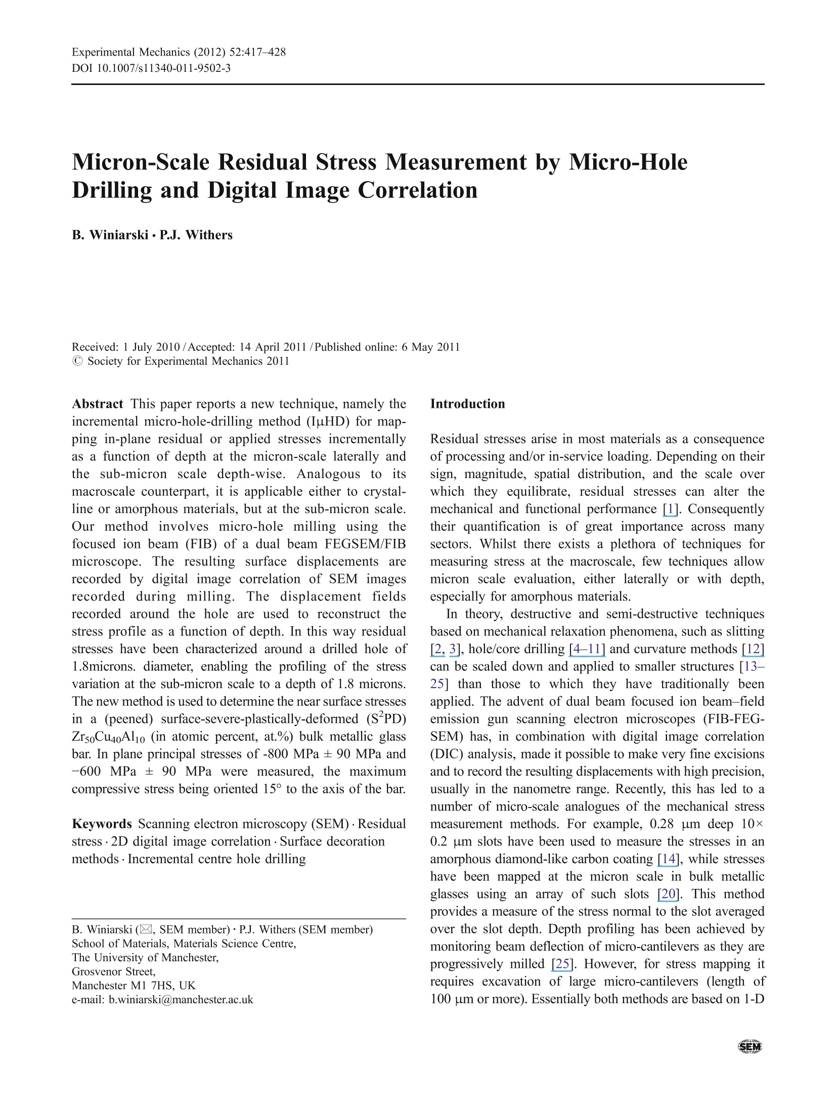
北京欧兰科技发展有限公司为您提供《Zr50Cu40Al10块体金属玻璃中表面形变,应变,残余应力检测方案(其它无损检测仪器/设备)》,该方案主要用于其他中理化分析检测,参考标准《暂无》,《Zr50Cu40Al10块体金属玻璃中表面形变,应变,残余应力检测方案(其它无损检测仪器/设备)》用到的仪器有LaVision StrainMaster材料应变形变成像测量系统。
我要纠错
相关方案
 咨询
咨询