

方案详情文
智能文字提取功能测试中
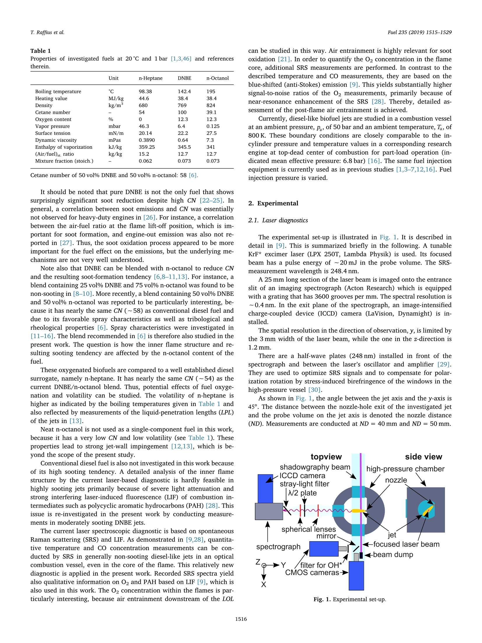
Fuel 235 (2019) 1515-1529Contents lists available at ScienceDirect Fuel 235 (2019)1515-1529T. Raffius et al. Fuel journal homepage: www.elsevier.com/locate/fuel Laser spectroscopic investigation of diesel-like jet structure using Cgoxygenates as the fuel Thomas Raffius ,*, Tamara Ottenwalder , Christian Schulz", Gerd Griinefeld, Hans-Jiirgen KoB,Stefan Pischingerb Institute of Technical Thermodynamics, RWTH Aachen University, Schinkelstr. 8, 52062 Aachen, Germany "Institute for Combustion Engines, RWTH Aachen University, Schinkelstr. 8, 52062 Aachen, Germany ARTICLEINFO ABSTRACT Keywords: Diesel Di-n-butyl ethern-Octanoln-HeptaneTemperatureCOO2 Raman Flame structure Di-n-butyl ether (DNBE) and n-octanol have very low sooting tendencies in diesel-like combustion, as demon-strated in previous engine studies. This finding is not fully understood for pure DNBE, because it has a very highcetane rating (~100). In order to investigate the underlying mechanisms, the structure of diesel-type jets isanalyzed by a number of optical diagnostics, such as spontaneous Raman scattering (SRS), laser-inducedfluorescence (LIF), OH* luminescence imaging, Mie scattering, and shadowgraphy. Pure DNBE and a tailor-madeblend of 50% DNBE and 50% n-octanol as well as neat n-heptane are used as the fuel in separate experiments.The jets are probed in a simulated engine-like environment in a high-pressure combustion vessel. In particular,the inner flame structure is analyzed by SRS and LIF. This yields information on the local temperature and theconcentrations of O2, CO, and polycyclic aromatic hydrocarbons (PAH). For the first time, 02 is quantitativelydetected in the core of a diesel-like flame by resonance-enhanced SRS. Thereby, air entrainment into the innerflame core is assessed. Results show that air entrainment is particularly strong for pure DNBE, explaining its highsoot oxidation rate and overall low sooting tendency. High entrainment is primarily attributed to the low heat-release rate of DNBE, which is likely an effect of its high ignitability. Thus, it can be concluded that the highcetane rating of pure DNBE does not only lead to relatively poor pre-combustion mixture preparation andconsequently considerable soot formation but seemingly also to particularly strong soot oxidation. Moreover, thejet structure turns out to be very similar for the DNBE/n-octanol blend and neat n-heptane, indicating that thenet effect of volatility and fuel oxygenation is weak. 1. Introduction Di-n-butyl ether (DNBE) and n-octanol are relatively new, promisingbiofuel candidates for diesel-type combustion [1-17]. They can be pro-duced from lignocellulosic biomass, which is not directly used as a foodsource [1,2]. By contrast, first-generation biofuels, such as ethanol andbiodiesel, are generally in competition with food supply [3]. It is alsoimportant to note that engine-out soot emissions can be reduced con-siderably by the new fuel candidates compared to conventional diesel fuel,without sacrificing NO, CO, and unburned hydrocarbon emissions [4]. The considered fuel species are isomers (CgH18O), but the oxygenatom is located at the end of the carbon chain in n-octanol, whereas it isin its center in DNBE. This leads to significantly higher reactivity ofDNBE. The fuel properties are summarized in Table 1 [1]. Note that thecetane number (CN) of n-octanol is ~39, whereas it equals ~100 forDNBE. Due to the high CN of pure DNBE, significant soot formation is expected (see, e.g., [18-20]). However,“surprisingly”low engine-outsoot emissions were found in [1,7]. Corresponding soot-volume fractionmeasurements by laser-induced incandescence (LII) in an optical dieselengine indicated that the soot reduction for DNBE compared to dieselfuel was caused by both reduced soot formation and enhanced sootoxidation [5]. The peak of the spatially averaged LII intensity, whichoccurred at ~15°crank angle (CA) for both fuels, was found to be~60% lower for DNBE compared to diesel, indicating lower soot for-mation for DNBE. Additionally, these measurements indicated that sootoxidation was stronger for DNBE because the LII intensity decreased by~88% between 15 and 22℃A for DNBE,whereas it decreased by“only”~40% for diesel fuel in that CA range. This behavior is not fully understood. It may be caused by the innerflame structure (see, e.g., [21]). Thus, the inner flame structure isanalyzed in the region where soot oxidation is the dominant process inthis work. E-mail address: thomas.raffius@ltt.rwth-aachen.de (T. Raffius). ( ht t p s :// doi.o rg/ 1 0 . 1016/j. f uel.2 0 18.07.124 ) ( Received 22 September 2017; Received in revised form 15 March 2018; Accepted 25 July 2018 ) ( Available online 20 September 2018 ) ( 0016-2361/C 2 018 Elsevier Ltd. All rights r eserved. ) Properties of investigated fuels at 20℃ and 1bar [1,3,46] and referencestherein. Unit n-Heptane DNBE n-Octanol Boiling temperature 98.38 142.4 195 Heating value MJ/kg 44.6 38.4 38.4 Density kg/m 680 769 824 Cetane number 54 100 39.1 Oxygen content % 12.3 12.3 Vapor pressure mbar 46.3 6.4 0.125 Surface tension mN/m 20.14 22.2 27.5 Dynamic viscosity mPas 0.3890 0.64 7.3 Enthalpy of vaporization kJ/kg 359.25 345.5 341 (Air/fuel)st. ratio kg/kg 15.2 12.7 12.7 Mixture fraction (stoich.) 0.062 0.073 0.073 Cetane number of 50 vol% DNBE and 50 vol% n-octanol: 58 [6]. It should be noted that pure DNBE is not the only fuel that showssurprisingly significant soot reduction despite high CN [22-25]. Ingeneral, a correlation between soot emissions and CN was essentiallynot observed for heavy-duty engines in [26]. For instance, a correlationbetween the air-fuel ratio at the flame lift-off position, which is im-portant for soot formation, and engine-out emission was also not re-ported in [27]. Thus, the soot oxidation process appeared to be moreimportant for the fuel effect on the emissions, but the underlying me-chanisms are not very well understood. Note also that DNBE can be blended with n-octanol to reduce CNand the resulting soot-formation tendency [6,8-11,13]. For instance, ablend containing 25 vol% DNBE and 75 vol% n-octanol was found to benon-sooting in [8-10]. More recently, a blend containing 50 vol% DNBEand 50 vol% n-octanol was reported to be particularly interesting, be-cause it has nearly the same CN (~58) as conventional diesel fuel anddue to its favorable spray characteristics as well as tribological andrheological properties [6]. Spray characteristics were investigated in[11-16]. The blend recommended in [6] is therefore also studied in thepresent work. The question is how the inner flame structure and re-sulting sooting tendency are affected by the n-octanol content of thefuel. These oxygenated biofuels are compared to a well established dieselsurrogate, namely n-heptane. It has nearly the same CN (~54) as thecurrent DNBE/n-octanol blend. Thus, potential effects of fuel oxyge-nation and volatility can be studied. The volatility of n-heptane ishigher as indicated by the boiling temperatures given in Table 1 andalso reflected by measurements of the liquid-penetration lengths (LPL)of the jets in [13]. Neat n-octanol is not used as a single-component fuel in this work,because it has a very low CN and low volatility (see Table 1). Theseproperties lead to strong jet-wall impingement [12,13], which is be-yond the scope of the present study. Conventional diesel fuel is also not investigated in this work becauseof its high sooting tendency. A detailed analysis of the inner flamestructure by the current laser-based diagnostic is hardly feasible inhighly sooting jets primarily because of severe light attenuation andstrong interfering laser-induced fluorescence (LIF) of combustion in-termediates such as polycyclic aromatic hydrocarbons (PAH) [28]. Thisissue is re-investigated in the present work by conducting measure-ments in moderately sooting DNBE jets. The current laser spectroscopic diagnostic is based on spontaneousRaman scattering (SRS) and LIF. As demonstrated in [9,28], quantita-tive temperature and CO concentration measurements can be con-ducted by SRS in generally non-sooting diesel-like jets in an opticalcombustion vessel, even in the core of the flame. This relatively newdiagnostic is applied in the present work. Recorded SRS spectra yieldalso qualitative information on O2 and PAH based on LIF [9], which isalso used in this work. TheO2 concentration within the flames is par-ticularly interesting, because air entrainment downstream of the LOL can be studied in this way. Air entrainment is highly relevant for sootoxidation [21]. In order to quantify the O2 concentration in the flamecore, additional SRS measurements are performed. In contrast to thedescribed temperature and CO measurements, they are based on theblue-shifted (anti-Stokes) emission [9]. This yields substantially highersignal-to-noise ratios of the O2 measurements, primarily because ofnear-resonance enhancement of the SRS [28]. Thereby, detailed as-sessment of the post-flame air entrainment is achieved. Currently, diesel-like biofuel jets are studied in a combustion vesselat an ambient pressure, P, of 50 bar and an ambient temperature, Ta, of800K. These boundary conditions are closely comparable to the in-cylinder pressure and temperature values in a corresponding researchengine at top-dead center of combustion for part-load operation (in-dicated mean effective pressure: 6.8 bar) [16]. The same fuel injectionequipment is currently used as in previous studies [1,3-7,12,16]. Fuelinjection pressure is varied. 2. Experimental 2.1. Laser diagnostics The experimental set-up is illustrated in Fig. 1. It is described indetail in [9]. This is summarized briefly in the following. A tunableKrF* excimer laser (LPX 250T, Lambda Physik) is used. Its focusedbeam has a pulse energy of ~20 mJ in the probe volume. The SRS-measurement wavelength is 248.4 nm. A 25 mm long section of the laser beam is imaged onto the entranceslit of an imaging spectrograph (Acton Research) which is equippedwith a grating that has 3600 grooves per mm. The spectral resolution is~0.4 nm. In the exit plane of the spectrograph, an image-intensifiedcharge-coupled device (ICCD) camera (LaVision, Dynamight) is in-stalled. The spatial resolution in the direction of observation, y, is limited bythe 3 mm width of the laser beam, while the one in the z-direction is1.2 mm. There are a half-wave plates (248 nm) installed in front of thespectrograph and between the laser’s oscillator and amplifier [29].They are used to optimize SRS signals and to compensate for polar-ization rotation by stress-induced birefringence of the windows in thehigh-pressure vessel [30]. As shown in Fig. 1, the angle between the jet axis and the y-axis is45°. The distance between the nozzle-hole exit of the investigated jetand the probe volume on the jet axis is denoted the nozzle distance(ND). Measurements are conducted at ND = 40 mm and ND= 50 mm. Fig. 1. Experimental set-up. 2.2. Diesel-like jet, high-pressure vessel, OH*-luminescence, andshadowgraphy A 3-hole (diameter: 109 um) diesel-like nozzle is attached to a piezodiesel injector. Fuel-rail pressures, Prail, of 700 bar, 1000 bar, and1500 bar are used. The energizing time (ET) of the injector is 1000 us. The high-pressure vessel shown in Fig. 1 is described in [8,10]. Itprovides neat air at stationary ambient pressure and temperature, pand Ta, of 50 bar and 800 K, respectively. As indicated in Fig. 1, the set-up for OH* imaging is implemented bya CMOS (complementary metal oxide semiconductor) camera (LaVi-sion, HSS6) with intensifier (LaVision High-Speed IRO). In front of theCMOS camera a filter (LaVision, filter 1108760) is installed. This filterhas a transmission of ~80% in the range from 300 nm to 340 nm. Anadditional filter (dielectric mirror) leads to an overall reduced detectionbandwidth (300 nm-320 nm). The camera is operated with a frame rateof 10kHz. The OH* luminescence is used to detect the LOL and ignitiondelay (ID) in the present work as described in more detail in [12]. As indicated in Fig. 1, high-speed (10kHz) jet visualization is alsoconducted by shadowgraphy, using a parallel light beam and a CMOScamera [8,10,13]. 3. Results 3.1. Overall jet characterization The transient behavior of the entire spray-combustion event is de-scribed first, based on a number of global quantities. Fig. 2 illustratesboth injection and high-temperature combustion as a function of tasoi(time after start of injection). As indicated by shadowgraphy, there is aconstant delay of 0.08 ms between the electronic trigger of the injectorand the actual start of injection. The three panels of Fig. 2 correspond tothe three investigated fuels described above. Each panel shows resultsfor three different injection pressures (Prail) as explained in the legend.The fuel injection event is characterized by the dynamic behaviour ofthe LPL, which is measured by high-speed Mie-scattering imaging in aseparate set of experiments as described in [13]. These curves show thatan apparently quasi-steady period (QSP) is established in terms of LPLfor all fuels and injection pressures. However, its length depends pri-marily on Prail· High-temperature combustion is characterized in terms of ID andLOL in Fig. 2 [12,20,31,32]. It is averaged over 20 injections (cyclicvariabilities are indicated in terms of standard deviation by scatterbands). The LOL curves commence at an ignition probability of 50%,i.e.,when ignition is observed in 50% of the injection events [20]. Hence, Fig.3. Ensemble-averaged OH* luminescence frames for Prail=1000 bar andtasoi =2.7 ms, corresponding to Fig. 2. Purple lines indicate used SRS/LIF laserbeam positions.“LPL” shows liquid-penetration length in its QSP. RD: Radialdistance. this tasoi value represents the (second-stage) ID. For instance, Fig. 3 shows typical ensemble averaged (20 shots) OH*images for Prail =1000 bar and tasoi =2.7 ms. The determination of theLOL is illustrated by white horizontal lines at the upstream edges of theOH* distributions. Similarly, the OH* penetration length (OHPL) isinferred from the downstream edges of the distributions, as also de-picted in Fig. 3. Both LOL and OHPL are determined from axial OH*signal intensity profiles (around the jet centerline), using a threshold of5% of the individual maximum [12]. The dynamic behaviour of the OHPL is shown in Figs. 2 and 4. InFig. 4, OHPL curves for all fuels are compared for Prail =1000 bar as anexample. In particular, Figs. 3 and 4 show that there is an interestingfuel effect. While the OHPL is similar for n-heptane and the DNBE/n-octanol blend, it is higher for pure DNBE late in the injection event. Thisis observed for all injection pressures, as shown in Fig. 2. The origin ofthis fuel effect is investigated below (Section 3.5). It should be noted that the OHPL does not necessarily correspond to Fig. 2. Overall jet characterization on the centerline for n-heptanea), the DNBE/n-octanol blend b), and DNBE c). Operating conditions: Ta =800K, Pa=50 bar, andET=1000 ms. Injection pressure is color coded.“SRS/LIF”indicates time and location of laser measurements. Panel a) adopted from [28]. Fig. 4. Typical ensemble-averaged GPL and OHPL curves for Prai=1000 bar,corresponding to Fig. 2. Fuels are color coded. GPL almost equal for all fuels. the entire gas-phase penetration length (GPL) of the jets. For instance,GPL curves measured by shadowgraphy are depicted in Fig. 4. Un-fortunately, GPL data are only available early in the injection event inthese particular measurements, including only a small fraction of thehigh-temperature combustion events. However, later-cycle GPL datawere presented in [13]. Figure 4 and [13] consistently demonstrate thatthere is not a significant fuel effect on the GPL, in contrast to the OHPL.The OHPL of pure DNBE is approximately equal to the late-cycle GPLdata of all the fuels. By contrast, the late-cycle OHPL of n-heptane andthe blend is shorter than the GPL. Thus, the entire flame length cannotalways be measured by OH* imaging. Figure 3 shows also the locations of the laser beam by purple lines.In Fig. 2, the time and ND of the SRS/LIF measurements is illustrated bydots on black horizontal lines. The colors of these dots indicate thecombustion phases in which the individual laser measurements areconducted, according to the legend of Fig. 2. This classification is basedon both the LOL and the SRS/LIF data presented below. The LOL curvesin Fig. 2 indicate that a QSP is established in the combustion events forall fuels and Praivalues. (This QSP is different to the one of the LPL,primarily due to the ID and the limited axial jet velocity. In the fol-lowing, QSP means the QSP of high-temperature combustion unlessotherwise noted.). However, the classification of the SRS/LIF mea-surements depends on both fuel and p. Note that the measurements atND= 50 mm and tasoi = 1.9 ms depicted in Fig.2a) are conducted in the“transient early”period at Prail=700 bar, whereas they belong to theQSP for the higher injection pressures. Accordingly, that dot in Fig.2a)has two colors. Note also that the classification often depends on Priclose to the end of injection (EOI) in Fig. 2a)/b)/c). The correspond-ingly colored dots indicate that the QSP is again established at thehigher injection pressures, while prai=700 bar yields “transient, late”conditions. All of the panels of Fig. 2 show that there is currently a negativeignition dwell, that is the time from EOI to ID [33]. This is usually alsothe case in conventional, sooting diesel combustion [33]. Indeed, con-siderable soot formation occurs in the current DNBE jets, in particularfor lower Prail. This is indicated by the yellow luminous flame, the lasermeasurements presented below, and also by soot luminosity detected inthe raw images of the LPL measurements (not shown for brevity). Bycontrast, the current n-heptane and DNBE/n-octanol jets are largelynon-sooting, as indicated by the mostly blue appearance of the flamesand by the laser measurements presented below. Soot formation wasinvestigated in more detail for the n-heptane jets in [28]. Briefly, highlyfuel rich, small regions, in which soot formation could be expected,were only found at Prail =700 bar. Presumably, the very low sootingtendency of the n-heptane and DNBE/n-octanol jets can be primarilyexplained by the long quasi-steady LOLs shown in Fig. 2a)/b). Since the GPL is essentially equal for all fuels as noted above, air entrainment andmixing upstream of the LOL are also expected to be similar [34]. Thus,the long LOLs of the n-heptane and DNBE/n-octanol jets indicate thatthe equivalence ratios at the LOLs (中ro) are lower than in the case ofpure DNBE. In addition, the proximity of the quasi-steady LOLs to thequasi-steady LPLs in Fig. 2c) suggests that ror is very high for DNBE, atleast at Prait= 700 bar. The lower LOLs of DNBE are basically attributedto its higher CN. Generally, soot formation decreases with increasing fuel oxygena-tion. However, the relatively high sooting tendency of pure DNBE foundin this work cannot be explained in this way, because the oxygencontent of DNBE is equal to the one of the blend and it is even highercompared to n-heptane. Apparently, the effect of oxygenation is not thedominant one. This may be explained by the fact that the degree ofoxygenation is relatively low in this work. Stoichiometric air/fuel ratio(by mass) and mixture fraction are given in Table 1. For instance, [18]shows that the effect of such a low oxygenation is limited. In general, the current n-heptane and DNBE/n-octanol jets are si-milar in terms of the global quantities considered so far. The only sig-nificant difference is the quasi-steady LPL, which is by~ 45% longer forthe blend, as shown in Fig. 2a)/b) and 3. 3.2. 1-d laser measurements Raw frames of the SRS/LIF measurements are not shown becausethey are essentially similar to the ones presented in [9,28]. (Recall thatthe frames are even identical in the case of the n-heptane jets in [28].)However, dispersion spectra inferred from the raw frames depicted inFig. 5 show interesting details. They are averaged over 20 shots (foreach fuel) and spatially integrated over 3 mm around the jet centerline.An injection pressure of 1000 bar is used and the measurements areconducted at tasoi =2,7 ms. Thus, the spectra show the typical situationin the QSP which is most important in this work. These measurementsare performed at an ND of 40 mm, which is problematic for pure DNBE.The most striking fuel effect on the spectra is that broadband emission,that is observed between the detected distinct SRS and LIF “lines”, isparticularly strong for DNBE. For clarity, corresponding measurementsin neat air are also presented in Fig. 5, in which there is not anybroadband emission. The spectra in Fig. 5 are normalized to the signal intensity at thepeak of the N-SRS“line”because N2-SRS is roughly a measure of lightattenuation [9]. Since N concentration and temperature are onlyslightly affected by the fuel type, as discussed in more detail below, N2-SRS almost directly shows the strength of attenuation. Thus, Fig.5demonstrates that the broadband signal is significantly higher for DNBEcompared to the other fuels after attenuation correction, because theratio of N2-SRS to broadband signal is lower for DNBE. The broadband signal is basically attributed to LIF from combustionintermediates, in particular PAH [35]. Minor contributions may arisefrom CO2-LIF [36]. In sooting regions, laser-induced incandescence(LII) from soot contributes to the signal [35]. Thus, it is not surprisingthat the broadband signal is particularly high in the discussed DNBE jetmeasurement. According to [33], strong broadband signal markssooting regions in diesel combustion. However, weak signals were alsofound in non-sooting diesel-like jets [28]. For brevity, the signal isdenoted PAH-LIF in the following. It is used as an indicator of sootprecursors and soot. Attenuation correction of SRS/LIF is conducted as follows. As shownin Fig. 5, the PAH-LIF is relatively smooth and structureless. Thus, al-most interference-free N2-SRS can be obtained by subtracting the in-terfering PAH-LIF which is determined by linear interpolation. For in-stance, this is illustrated by a black line in Fig. 5 for the spectrum of theblend. The black line is based on pure PAH-LIF signals obtained in the“background”channels denoted BG1 and BG2. This works well for non-or low-sooting conditions. However, Fig. 5 indicates also that un-certainties may occur in the considerably sooting DNBE jet at wavelength/nm Fig.5. Typical ensemble-averaged Stokes dispersion SRS/LIF spectra measured on the centerline of the jet at ND=40 mm, Prail =1000 bar, and tasoi =2.7 ms. Otheroperating conditions as in Fig. 2. Straight black line indicates linear interpolation of PAH-LIF. Neat air spectrum is also shown. ND =40 mm, because of the significantly stronger PAH-LIF.This holdsnot only for the determination of pure N2-SRS signals but also for PAH-LIF subtraction in the case of CO-SRS and O2-LIF signals, which isconducted essentially in the same way. The spectroscopy of CO-SRS is particularly challenging because ofinterfering emissions from both N2-SRS and PAH-LIF. Thus, this issue isinvestigated in more detail in the following. Recall that CO-SRS mea-surements were previously only conducted in (largely) non-sooting jetsby the current diagnostic [9,28]. Figure 6 depicts typical “worst-case”spectra for the DNBE jet. Theyare determined on the centerline as in Fig. 5. However, the spectra inFig. 6 are averaged over a higher number of laser shots for clarity. Thus,shot noise is very low. 120 shots are used for each of the ND-values of40 and 50mm. It is important to note that the apparent PAH-LIFbackground is approximately linear in the range of CO- and N2-SRS inFig.6a). Thus, the simple background-subtraction strategy applied tothe low-sooting jets can also be used for DNBE. (One major reason is therelatively high spectral resolution of the spectrometer.) It is again in-dicated by straight black lines in Fig.6a). The most challenging condition (at ND= 40 mm) is also in-vestigated in Fig. 6b). It depicts the concerning spectrum of panel a)after background subtraction in the range of the CO-and N2-SRS bands.Figure 6b) illustrates also the best fitting theoretical spectrum of the N2-SRS, which is determined as described in [9].Obviously, it is essentiallyconsistent with the experimental spectrum. (This seems to confirm thatbackground subtraction is appropriate.) Consequently, the temperaturecan be inferred from the N2 band and its signal cross-talk in the range ofthe CO-SRS can be determined from the theoretical spectrum.Overall,Fig. 6 indicates that both interfering PAH-LIF and N2-SRS can be quiteaccurately subtracted from the signal in the range of CO-SRS. The re-sulting signal-to-noise ratio of CO-SRS is very good. (One major reasonthat this also holds for the challenging, sooting jet region atND= 40 mm is that the CO mole fraction is very high there, seeFig. 6b)). After background subtraction, the quantification of CO is straight-forward. Briefly, the simultaneously recorded N2-SRS yields an at-tenuation-correction factor ([9] and references therein). The measuredtemperature is also taken into account because the ratio of CO- to N2-SRS cross-sections depends on this factor. Interestingly, one of themajor findings of the CO measurements in the current DNBE jets isalready observed in Fig. 6a). Obviously, both PAH/N2 and CO/N2 aresignificantly higher at ND = 40 mm compared to ND = 50 mm. Figure 5 also illustrates that the N2-SRS signal is integrated in thespectral area of interest (AOI) to reduce shot noise. Temperature mea-surements are based on the same AOI [9]. Integrated N2-SRS signals areused for attenuation correction of PAH-LIF, O2-LIF, and CO-SRS, asdiscussed in more detail in that prior work. Attenuation corrected PAH-and O2-signals are denoted PAH/N2 and O2/N2. As shown in Fig. 5, there are two O2-LIF emission “lines”in thedetected spectral range. The O2-LIF“line”at ~266nm is exploited inthis work because it is stronger than the“line”at ~257 nm. For brevity, only ensemble averaged (20 shots unless otherwisenoted) species concentrations are considered. By contrast, temperaturemeasurements are based on single-shot N2-SRS data to avoid averagingerrors. A certain fraction of the raw images could not be reliably con-verted to temperature at some of the x-positions, in particular for DNBEat ND=40 mm. Primarily, this is caused by lacking signal intensity,i.e., shot noise. This is consistent with [28]. For instance, Fig. 7 showsthat the measurement-failure probability increases strongly with de-creasing N2-SRS signal level. In that plot, the signal intensity is given interms of the photoelectron numbers (generated in the photocathode ofthe image intensifier) obtained from all of the conducted single-shotmeasurements in individual probe-volume elements (extension along x-axis: 3mm) for DNBE at ND= 40 mm. It is plausible that light at-tenuation is particularly strong in the sooting region. Due to the signal-intensity dependence of measurement failure, it isgenerally higher on the left side of the radial profiles. This is plausiblebecause the laser beam is attenuated as it progresses through the probevolume from right to left. This radial asymmetry of measurementfailure is used to study its effect on the temperature measurements.Mean temperature profiles are expected to be essentially symmetric atleast in the QSP [9,28]. However, some of the measured profiles areclearly asymmetric at very high measurement failure rates (> 60%) forDNBE at ND = 40 mm. Thus, the measurements at Prail=700 bar andtasoi = 1,4 ms as well as at 1000 bar for 1.4 and 1.9 ms are discarded. The effect of measurement failure on the remaining temperaturedata is tolerable, as demonstrated in the following. In Fig. 8,“worstcase” measurements are analyzed as an example. The consideredmeasurements are conducted at Prai= 700 bar (1.9 ms, ND=40 mm)and 1000 bar (1.9 ms, 50 mm), respectively. They have the highestmeasurement failure rates in the remaining data sets measured atND=40 mm and 50 mm,respectively. Figure 8a) shows the concerningmean temperature profiles. The left half of each profile is mirrored andalso plotted in the right half (dashed curves) to analyze symmetry. wavelength/nm wavelength/nm Fig. 6. Analysis of the spectroscopy of CO and temperature measurements in DNBE jets on centerline at tasoi =2.7 ms. Each measured spectrum averaged over 120shots (including all investigated Pra-values, which have little effect on the data).“Raw”spectra normalized to N2-SRS peak signal (a). Measured spectrum forND = 40 mm after background subtraction along with fitting theoretical N2-SRS spectrum (b). Fig.7. Probability density function (pdf) of measurement failure with regard toStokes N2-SRS signal intensity, taking all measurements with pure DNBE atND = 40 mm into account. Operating conditions as in Fig. 2. Obviously, the profiles are nearly symmetric, although the corre-sponding measurement failure rate is relatively high and stronglyasymmetric, as shown in Fig. 8b). The apparent weakness of the effectof measurement failure on measured mean temperature may be ex-plained by relatively low shot-to-shot temperature variability at least inthe QSP around the centerline (see below). The effect of measurementfailure on the main results is also minimized by considering particularlyradial profiles measured in the late QSP (tasoi = 2,7 mm). In thesemeasurements, the failure rate is generally lower than in the examplespresented in Fig. 8. For instance, it is roughly 30% at ND = 40 mm andless than 20% at ND= 50mm for DNBE on the centerline (all Pra va-lues,see below). For the blend and n-heptane, corresponding values arealways< 15%. The shot-to-shot temperature variability of n-heptane jets in the QSParound the centerline is described in [28]. The relative variability(~8%) is similar for the other fuels (not shown for brevity). Only theDNBE/n-octanol jet at Prail =1500 bar and ND = 40 mm is different(~50%) because it is measured near the LOL (see Fig. 2b) and Section3.3). In addition to the Stokes SRS/LIF measurements discussed so far,corresponding spectra are recorded in the anti-Stokes range by x-position / mm Fig. 8. Mean temperature profiles for DNBE with p=700bar at ND= 40 mm and for 1000 bar at 50 mm (both at tasoi =1.9 ms, a). Mirrored left half of each curvealso shown in right half (dashed lines). Vertical lines indicate jet centerline. Measurement uncertainty shown by bars [28]. Other operating conditions as in Fig. 2.Failure rate of measurements in a) is given in b). 1 Fig. 9. Averaged dispersion spectra for the three fuels (see legend) at tasoi = 2.7ms, Prail=1500bar, and ND=50 mm. Other s,Prail=operating conditions as in Fig. 2.Broadband background (small constant offset) is subtracted and spectra are normalized to N2-SRS intensity. adjusting the spectrograph. For instance, Fig. 9 shows a typical dis-persion spectrum for each fuelacquired at ND=50 mm,Prail=1500 bar, and tasoi=2,7 ms.Each spectrum is averaged over 40injections to reduce shot noise.It is also integrated over x=3 mmaround the centerline, as in the case of Fig. 5. Each jet spectrum showstwo O2-LIF emission bands (at ~232 and ~240 mm) as well as SRSfrom N2 and CO, as illustrated in Fig. 9. Most importantly, there is alsonoticeable O2-SRS in the DNBE-jet spectrum. The concerning part of thespectrum is also depicted in the inset of Fig. 9 for clarity. An additionalspectrum measured in neat air (grey curve) shows the spectral positionof O2-SRS. The jet O2-SRS signal is much weaker than the adjacent O2-LIF band, so that O2-SRS is more strongly affected by shot noise.However,O2-SRS can be quantified in the present state [37], in contrastto O2-LIF. In the DNBE-jet measurement shown in Fig. 9, the resultingO2 concentration is 0.6%±0.3%. The uncertainty is primarily causedby the interfering O2-LIF band and shot noise. The estimated spectralshape of the O2-LIF in the range of the O2-SRS is indicated by a dashedline in the inset of Fig. 9. The resulting shaded area is used for quan-tification. The given uncertainty shows that the discussed O2-SRS signalis close to its detection limit. Interestingly,it can only be detected be-cause of resonance enhancement [37]. Therefore, the O2-SRS detectionlimit is significantly lower than for corresponding measurements in theStokes spectral range. For instance, the resonance-enhanced O2-SRSsignal from neat air is stronger than the corresponding N2-SRS in Fig. 9, whereas the opposite is the case in the Stokes measurement shown inFig. 5. Accordingly, O2-SRS is not found in the jet spectra in Fig.5,although there is O2 present in the probe volume as shown by the moresensitive O2-LIF. This is the reason why anti-Stokes SRS is used. Figure 9 also demonstrates that the O2 concentration is noticeablyhigher in the DNBE jet compared to the other jets, as indicated by bothO2-SRS and O2-LIF. Essentially, no O2-SRS is observed in the n-heptaneand DNBE/n-octanol jets. This is primarily caused by shot noise whichis, for instance, obvious around 238.5 nm. Due to the higher sensitivityof O2-LIF, it is primarily used to show O2 distributions qualitatively forall fuels and conditions in this work. However, since excited vibrationalstates (v=6 and 7) are probed, only hot O2 is detected by O2-LIF. Note also that the finding that O2-LIF is higher in the DNBE jet thanin the other fuel jets in Fig. 9 is not caused by effects of temperature orattenuation. For instance, when the O2-LIF at ~240 nm is corrected forthe effects of these two quantities, it is by a factor of ~2.2 higher thanin the DNBE/n-octanol jet. The corresponding factor for the n-heptanejet is even ~4.8. Figure 9 indicates also that there is hardly any sign of broadbandPAH-LIF and soot luminosity/LII, because very low signal intensities arefound around 233.5 and 237.2 nm. This is another advantage of anti-Stokes detection with relatively high resolution. The major conclusionsdrawn from the centerline spectra in Fig. 9 are supported by the otherspectra acquired at various x-positions for the same operating Fig. 10. Averaged dispersion spectra for pure DNBE at laser-exit side normal-ized to O2-LIF peak at~240 nm, (a). Operating conditions as in Fig. 9. Aver-aged O2 concentration profiles for the three fuels (see legend). conditions. For instance, Fig. 10a) depicts normalized“raw"spectra forthe entire laser-exit side of the concerning DNBE jet measurement.Dashed lines show the estimated, curved“background”of the O2-SRS.Importantly,higher O2-SRS signals with better signal-to-noise ratios arefound off the centerline. Quantitative O2 mole-fraction profiles measured by anti-Stokes SRSare presented in Fig. 10b). The operating conditions are again the onesof Fig. 9. It is important to note that the entire O2 profile of the DNBEjet is higher than the ones of the other fuels. This difference is obviouslyhigher than the error bars at least at x= 19 mm. The O2 profiles are obtained as follows. Jet spectra are normalized bymeasurements in pure, homogeneous air (50 bar, 800 K) conducted shortlybefore and after the jet measurements.“Background” is subtracted as in-dicated in Figs.9/10a). The temperature dependence of O2-SRS is takeninto account based on previously discussed thermometry by Stokes N2-SRS.Attenuation correction is conducted by interpolating the data obtained atanti-Stokes and Stokes N2-SRS wavelengths [9]. The measurement un-certainty given by bars in Fig. 10b) is determined by taking the standardsampling error and contributions by shot noise and the errors of tem-perature, attenuation, and O2-LIF cross-talk correction into account. To the authors'knowledge, O2 is measured quantitatively (by SRS)for the first time in the central region of a quasi-steady diesel (-like) jet,compare Fig. 2. It may be surprising that there is such a high 02 concentration in the DNBE jet core so that it can even be measured bySRS. In conventional diesel jets, entrained ambient O2 is most likely toreact at the diffusion flame on the periphery, rather than being en-trained into the jet core [19]. The fuel/air ratio at the LOL, 中ror, wasexpected to be important for the sooting tendency because air en-trainment into the jet core was assumed to be prevented downstream ofthe LOL so that soot was formed in the inner fuel-rich reaction zone[38-40]. The present O2 measurements indicate that 中zor is less im-portant for the sooting tendency than previously thought at least for theDNBE jet. Factors other than 中ro are important to overall soot pro-duction. 3.3. Multiscalar profiles To characterize jet structure in the QSP, quantitative temperature andCO as well as qualitative PAH/N2, 02/N2, and OH* radial profiles aregiven for n-heptane, DNBE/n-octanol, and DNBE in Figs. 11-13, respec-tively. All measurements are conducted at tasoi = 2.7 ms and averaged over20 injections. Injection pressure and ND are varied, according to captions.The jet centerline is located at x =11.7 mm in Fig. 11/12/13. In general, the data are similar for n-heptane and the blend in Fig. 11/12, while the ones for DNBE in Fig. 13 are strikingly different. In parti-cular, there is a fuel effect on PAH/N2, CO, and O2/N2 profiles. AtND = 40 mm, peak PAH/N2 and CO data are significantly higher for DNBEcompared to the other fuels, reflecting the increased sooting tendency ofDNBE.As noted above, these measurements are performed in the sootingregion of the DNBE jets. Most importantly, PAH/N2 and CO values de-crease dramatically with increasing ND for DNBE, as indicated byFig. 13b)/d)/f). This is not observed for the other fuels in Figs. 11/12. Since the thickness of the PAH/N2 and CO distributions is not sig-nificantly larger at ND = 50 mm compared to 40 mm for DNBE, de-creasing peak intensities can hardly be explained by turbulent mixing.The most likely explanation therefore is that soot (precursors) and COare primarily oxidized for DNBE. This is supported by the findings thattemperature is high enough and O2 is always observed even on thecenterline. The quantification of the O2 concentration presented inSection 3.2 shows that it is not negligible. That O2 concentration of0.6% corresponds to Fig.13f). For the other injection pressures, similarcenterline O2/N2 signals are found, as shown in Fig. 13b)/d). Since theO2-LIF is primarily temperature dependent and the centerline tem-peratures are very similar in Fig. 13b)/d)/f), it can be assumed that thecenterline O2 concentration is also hardly affected by injection pressure. Interestingly, these relatively high centerline O2 concentrations are onlyfound for DNBE at ND= 50 mm. While there is always a pronounced dip inthe O2/N2 profiles close to the centerline for the other ND-value and fuels,this dip nearly vanishes for DNBE at ND= 50 mm. Temperature correctionof these O2-LIF data (not shown for brevity) consistently yields highercenterline intensities for DNBE compared to the other fuels. This may beexplained by particularly strong air entrainment for DNBE. Since O2 is most likely consumed by the diffusion flame on theperiphery of the jets [19], it may be concluded that OH is also alwayspresent on the centerline for all the fuels. This is important because OHis particularly relevant for soot oxidation. The interpretation of the OH*profiles depicted in Figs. 9/10/11 suffers from line-of-sight detectionand possibly interfering soot incandescence [41]. However, the as-sumption of non-vanishing centerline OH concentrations is at least notruled out by corresponding Abel-inverted OH* profiles (not shown forbrevity), which are always non-vanishing on the centerline. In general, the observed effect of Prai on the data in Figs. 11/12/13is relatively weak. This may be surprising because 中LoL is presumablyaffected by Pr for each of the fuels, as indicated by the varying LOL-values in the QSP in Fig. 2. The Prai-effect is particularly weak forDNBE, i.e., in Fig. 13. This may be explained by the fact that themeasurements are conducted relatively far away from the LOL andstrong effects of mixing/entrainment for this fuel. Overall, the strongest impact of Prai is found for the blend at PAH/N2/a.u.OH*/a.u. Fig. 11. Averaged multiscalar (see legend) radial profiles for n-heptane at tasoi=2.7 ms, Prai=700 bar (a, b), Prait=1000 bar (C, d), Prait=1500 bar (e, f),ND= 40 mm (a, c, and e), ND= 50 mm (b,d, and f). Other operating conditions as in Fig. 2. Measurement uncertainty shown by bars. Temperature and CO dataadopted from [28]. ND=40 mm, i.e., in Fig. 812.a)/c)/e). Relatively low temperaturesshown in Fig. 12e) indicate incomplete combustion for Prai=1500 bar.This can be explained by the fact that these particular measurementsare performed very close to the LOL, as illustrated in Fig. 2b). Indeed,the particularly strong OH* peak signal in Fig. 12e) shows that theprobe volume is located in the region of the premixed burn, compareFig. 3. Distinct dips in both temperature and CO profiles are found onthe centerline in Fig. 12e), in contrast to all other panels of Figs. 11/12/13. This may be caused by particularly retarded combustion on thecenterline in Fig. 12e). 3.4. Analysis in entire QSP Recall that the discussion of the laser measurements is only based on a single data acquisition time (tasoi =2.7 ms) in the prior section. This ismotivated by the assumption that combustion is approximately quasi-steadyin its QSP. However, more measurements at other tasoi-values are conductedas illustrated in Fig. 2. Even in the QSP of high-temperature combustion, theresults of the laser measurements are certainly not precisely equal. Forbrevity, multiscalar plots are only presented for tasoi =2.7 ms. To sum-marize all quantitative temperature and CO measurements on the centerlinein the QSP briefly, Fig. 14 is presented. These data are averaged over theentire QSP of high-temperature combustion, as indicated in Fig. 2, and re-presented by one data point for each fuel and Prai. Variability within theQSP is indicated by bars. One might also ask how close the experimental data are to corre-sponding adiabatic-equilibrium calculations. For instance, initial NOformation in the current n-heptane jets can be quite accurately b) 3000 1 0.8 0.6 0.4 0.2 0.8 0.6 0.4 0.2 0.8 0.6 0.4 0.2 CO/mole fraction O2/N,/a.u.PAH/N,/a.u.OH*/ a.u. predicted by kinetic homogeneous-reactor calculations [42]. Thisfinding appears to be consistent with the observed relatively low mixingeffects for n-heptane. In this case, temperature and Co data may beclose to adiabatic equilibrium conditions, if combustion is not sig-nificantly retarded. The retardation of combustion is another inter-esting effect that may be observed in the data. In Fig. 14, dashed linesshow adiabatic equilibrium data which are calculated using the reac-tion mechanism presented in [43,44]. For the blend, precise calculateddata are not available. However, corresponding curves for both pureDNBE and pure n-octanol given in Fig. 14b) demonstrate that there isalmost no fuel effect. Thus, the actual data of the blend are expected tobe similar to the ones of the pure components. Overall, Fig.14 confirms that the experimental data of the DNBE jetare strikingly different to the ones of the other fuels. The latter arerather similar. In particular, CO concentrations are different. There is a strong axial gradient for DNBE in contrast to the other fuels, as notedabove. There is no such strong fuel effect on the temperature data.Results for the blend at Prail=1500 bar and ND =40 mm are omitted inFig.14b) because they are measured very close to the LOL as noted inthe prior section. The corresponding temperature for Pri=1000 barshown in Fig. 14b) is relatively low, presumably, due to the same effect.As suggested in [28], the centerline mean temperature increases slowlydownstream of the LOL, potentially because of turbulence-chemistryinteraction. Thereby, the relatively large deviation from adiabatic-equilibrium results of the data point measured at Prai=1500 bar andND=40 mm in Fig.14a) was explained. Interestingly, the data points for ND= 40 mm are clearly above theadiabatic-equilibrium curve for the DNBE jet (see Fig. 14c)), in contrastto the other fuels. A similar, less pronounced deviation is observed forthe data measured at ND= 50 mm in the n-heptane jets, see Fig.14a). Fig. 13. Averaged multiscalar (see legend) radial profiles for DNBE at tasoi =2.7 ms,Pral = 700 bar (a, b), Prail=1000 bar (c, d), Prail = 1500 bar (e, f), ND =40 mm(a, c, and e),ND= 50 mm (b,d, and f). Other operating conditions as in Fig. 2. Measurement uncertainty shown by bars. This may be explained by the inhomogeneity of the mixture [28]. Heattransfer to fuel-rich zones may lead to super-equilibrium CO con-centrations. As suggested in Section 3.3, air entrainment appears to be strongerfor DNBE compared to the other fuels. Presumably, this fuel effect canbe explained by the heat-release rate. It was found to be particularlylow for DNBE in previous engine experiments, due to its high CN [3,7].According to [21,45], entrainment increases with decreasing heat-re-lease rate.Thus, soot oxidation seems to be enhanced by the high CN ofDNBE. 3.5. Origin of OHPL variation As noted previously, there may be soot-luminosity cross-talk in theOH* measurements. However, according to conceptual models of sooting jets in [33], the soot distribution is always surrounded by an OHdistribution at the flame tip. Thus, the OHPL measurement appears tobe not directly affected by luminosity cross-talk. However, it may beaffected rather indirectly as follows. As noted above, the determinationof the OHPL depends not only on the signal distribution at the flame tipbut also on the maximum of the entire OH* signal profile. Generally,the OHPL decreases with increasing OH* maximum. Thus, slightlyshorter OHPLs are likely measured in sooting jets, if the signal intensitymaximum is increased by luminosity. However, this seems to be aminor effect because the measured OHPL tends to increase with in-creasing sooting tendency, as demonstrated in Fig. 3 and in the fol-lowing. Overall, the conclusions of the OHPL measurements seem to benot affected by possible luminosity cross-talk. As noted in Section 2.1, the OHPL is longer for DNBE than for theother fuels considered so far. By contrast, GPL data are essentially a) 2800 ▲ Prail=700 barprail=1000 barprail= 1500 bar Fig. 14. Quasi-steady mean temperature and CO data along with adiabaticequilibrium curves (dashed lines).“Error”bars indicate variability of ensemble-averaged (20 shots) measurements. Operating conditions as in Fig. 2. N-hep-tane, DNBE/n-octanol, and DNBE data are shown in a), b), and c). Panel a) isadopted from [28]. equal, so that jet velocities are also likely similar. Thus, the longerOHPL of DNBE (and its lower LOL) indicates a longer residence time ofthe fluid parcels in the high-temperature reaction zone. This may havean effect on soot processes [21]. Therefore, the origin of the OHPLvariation is investigated in the following. OHPL and GPL are measured for a larger ensemble of fuels given inTable 2. CN and fuel oxygen content are particularly considered. Recallthat premixing may be affected by CN. Measured GPL variations are insignificant [13], so that they are notshown here. However, significant OHPL variations are observed. Forinstance, in Fig. 15, OHPL-values at tasoi =2.7 ms for all fuels are pre-sented. Since CN may not precisely correspond to the actual ignitability[3], the effects of ID and LOL are also investigated in Fig. 15a)-f). Table 2Properties of investigated fuels. fuel CN/- oxygen content/% 1 oxymethylene dimethyl ethers-2*(OME) 60 45.3 2 OME-3 70 47.1 3 OME-4* 80 48.2 4 OME-3*,-4*,-5* 83 48 5 n-dodecane 72.9 0 6 n-heptane 52.8 0 7 diesel 56 0.14 8 di-n-butyl ether (DNBE) 100 12.3 9 20vol% DNBE, 80 vol%n-octanol 45 12.3 10 35 vol% DNBE, 65 vol%n-octanol 52 12.3 11 50 vol% DNBE, 50 vol%n-octanol 58 12.3 12 65vol% DNBE, 35 vol%on-octanol 68 12.3 13 80 vol% DNBE, 20 vol%n-octanol 81 12.3 14 20 vol% dioctyl ether, 80 vol%n-octanol 48 12.3 15 45 vol% dioctyl ether, 55 vol%on-octanol 62 12.3 * Chemical characterization of OME-n: H3C-O-(CH2O)n-CH3. ’ Mixture: 49 vol%OME-3, 29 vol%OME-4,22 vol%OME-5. Injection pressure is again varied in the range from 700 to 1500 bar,according to the different columns of panels in Fig. 15. Table 2 demonstrates that the OME fuels have a substantially higheroxygen content than the other fuels. Thus,OME fuels are represented byblue data points in Fig. 15. Red data points correspond to the threeselected fuels considered in the previous sections. All other fuels arerepresented by black data points. Numbers in Fig. 15 correspond to theorder of the fuels in Table 2. The scatter plots in Fig. 15 show that the OHPL of the OME fuelstends to be lower compared to the other fuels for increased injectionpressure (panels b), c), e), f), h), and i)). For instance, a typical quasi-instantaneous (single shot) composite image acquired at tasoi =2.7 mswith Pra =1000 bar for OME-3 depicted in Fig. 16 demonstrates thatthe OHPL is indeed significantly shorter than the GPL. This is not adynamic effect, because these measurements are conducted in the QSP.(This also holds for all the other fuels.) It is plausible that this strongeffect is primarily caused by the high oxygen content of the OMEs,because it causes the stoichiometric mixture-fraction contour to becloser to the central region of the jet [21]. However, Fig. 15e)/f) showthat fuel/air premixing may also contribute to this effect, since LOL-values of the OMEs are relatively high, in particular for increased in-jection pressure. The effect of ignition quality is studied without large changes in fueloxygen content by considering the black and red data points in Fig. 15.To investigate whether there are correlations between OHPL and ig-nitability, linear regression for these data points is illustrated by blacklines in Fig. 15. Corresponding correlation coefficients (R2) are given inFig. 15. All the black lines consistently indicate that there is a corre-lation between ignitability andOHPL, although some of the R-valuesare low. This seems to confirm that premixing has an effect on theOHPL. Thus, there is likely relatively lean mixture in the gap betweenOHPL and GPL. 4. Summary and conclusions DNBE and n-octanol are promising biofuel candidates as demonstratedin recent studies. However, detailed experimental data on the inner flamestructure in diesel-like jets are lacking. Thus, 1-d SRS/LIF measurementsare conducted in such jets in a simulated engine environment. Pure DNBEand a blend of 50% DNBE and 50% n-octanol as well as n-heptane are usedin separate experiments under identical conditions. Pure DNBE is parti-cularly interesting because its sooting tendency is surprisingly low despiteits high CN. The selected blend was recommended in previous work. Thecurrent question is whether the flame structure is comparable to the one ofa well established diesel surrogate, namely n-heptane. Stokes SRS/LIFmeasurements yield quantitative temperature and CO as well as qualitative a) 3.0 OHPL /mm Fig. 15. Ensemble-averaged (20 injections) scatter plots of global quantities for the fuels given in Table 2. Measurement time is tasoi =2.7 ms, Prai =700 bar (a, d,g),1000 bar (b,e, h), and 1500 bar (c, f, i). Other operating conditions as in Fig. 2. O2 and soot (precursor) data. Additionally, the O2 concentration is quan-tified for the first time by an anti-Stokes SRS measurement in the DNBE jet.Both O2-SRS and O2-LIF indicate that there is air entrainment into the coreof the quasi-steady DNBE jet. This may be surprising because it is notexpected for conventional diesel jets. Apparently, mixing is stronger in thecurrent DNBE jets. Based on the O2 measurements, it can also be stated that air en-trainment appears to be particularly strong for the DNBE jets. This maybe explained by the lower heat-release rate of this fuel. Both soot(precursor) and CO data indicate that mixing leads to surprisinglystrong oxidation of these species in the central region of the DNBEflames. Thereby, the previously observed low sooting tendency of DNBEmay be explained. Since the low heat-release rate of DNBE is likely caused by its highCN, particularly strong soot oxidation is apparently also caused by thehigh ignitability. Thus, both soot formation and oxidation are pre-sumably promoted by CN. This may be one reason why a clear effect ofCN on the overall sooting tendency was previously not observed inheavy-duty diesel engines. O2-LIF is always detected in the quasi-steady jet core for all thefuels. Since air entrainment into the jet core is not prevented down-stream of the LOL, 中io appears to be less important than previouslythought. This is also indicated by the generally weak prai-dependence ofthe temperature and species data measured in the central region of thejets, in particular for DNBE. Overall, the DNBE/n-octanol-blend and n-heptane jets are similar in ND/mm Fig. 16. Single-shot composite image acquired in OME-3 jet at tasoi =2.7 ms forPrail= 1000 bar. Colored area: OH* luminescence; red line: jet boundary in-ferred from shadowgraphy shown in background; yellow line: boundary ofdroplet distribution according to Mie scattering image. terms of both inner flame structure and global quantities. Therefore, thenet effect of primarily different volatility and oxygen content of thesefuels appears to be weak. By contrast, the DNBE jets are strikingly different. A strong axialgradient (ND-dependence) in the inner flame structure data is onlyobserved for DNBE. Particularly high (“super-equilibrium”) CO con-centrations measured in the sooting region of the DNBE jets may beexplained by heat transfer from near-stoichiometric zones to highlyfuel-richones. Since soot processes may also be affected by the residence time ofthe fluid parcels in the high-temperature reaction zone, it is interestingto note that the OHPL is generally longer for DNBE compared to theother fuel candidates considered so far. The analysis of a larger fuelensemble indicates that this is an ignition-quality effect. Acknowledgment This work was performed as part of the Cluster of Excellence“Tailor-Made Fuels from Biomass”, which is funded by the ExcellenceInitiative by the German federal and state government to promotescience and research at German universities. ( References ) ( [ 1] H euser B, Laible T , Jakob M, Kr e mer F, Pischinger S. C8-oxygenates for clean diesel combustion. SAE Tech Paper 2014;2014-01-1253. doi:h ttps :// d o i . or g /1 0 . 4 2 7 1 / 2 0 1 4 - 0 1 -1 253 . ) ( [2] J ulis J, Leitner W. Synthesis of 1 -octanol and 1,1-dioctyl ether from biomass-derivedplatform chemicals. Angew Chem I n t Ed 2012;51(34):8615-9. h t t p s : //d o i . o r g / 1 0. 1 0 0 2/ an ie . 2 0 1 2 0 3 669 . ) ( [ 3 ] K erschgens B , Cai L, Pitsch H , H euser B, Pischinger S. D i-n-butylether,n-octanol, a nd n-octane as fuel c andidates for d iesel engine combustion. Combust Fl a me 2016;163:66-78. h t t p s : / /do i.org /10 .1 0 1 6/j. co mbustfla m e .20 1 5.09. 0 01 . ) ( [ 4] H euser B, Mauermann P, W a nkhade R, Kremer F, Pi s chinger S. Combustion andemission b e havior of linear C8-oxygenates. In t J Eng Res 2015;16(5):627-38. h t tp s://d o i . o rg /1 0 . 1 1 77 / 1468087415594951. arXiv:https://doi.org/10.1177/1468087415594951. ) ( [ 5] K lein D, Pischinger S . L aser-induced incandescence m e asurements of tailor-made f uels in an optical single-cylinder d iesel engine. SAE I n t J Eng 2017;10(3):1143-54. h t tps ://d o i .o r g /1 0 .4271 / 20 1 7- 0 1 - 0 7 11. ) ( [6] R uck e r t M , Z ube l M , W eine b e ck A, M u r renhoff H, P isc hinger . H o lli s t ic inv e s ti g at ion o f a 5 0 /50 DnBE-1 - oc ta n o l ble n d r e g a r d i ng t h e c ompl ete i nj e ct io n s ys t e m . 5 t h T MFB i n t ernational confere nce aa c h e n . 201 7 . ) ( [7] Z 1 u b e l M, P i schinge r S, He u ser B . A ss essment of t h e f u ll t h e rmodynami c po t ential of C 8 - o x yg e na t e s f o r cl e an diesel c o mbusti o n. S A E I n t J F u e ls L u b r 2 01 7;10 ( 3 ) . ) ( [8 ] O ttenwalder T, Ra f fius T, Schulz C, Brands T, Hii l ser T, Gr i inefeld G, et al . Optical i nvestigation of biofuel effect s on NO and PAH f o rmation in diesel-like j ets. SAE Tech P aper 2015;2015-24-2485.doi:ht t ps ://do i. o rg /1 0 . 427 1/ 201 5-24-2 4 85. ) ( [9] R affius T, Schulz C , Ottenwalder T, Gr i inefeld G, Brands T, K o HJ, e t a l . F lame-temperature, light-attenuation, and CO measurement s by spontaneous Raman s cattering in non-sooting diesel-like jets. Combust Flame 2017;176:104-16. h tt ps :// d oi.o rg / 1 0. 1 016/ j. co mbust f la m e . 2 0 1 6 .0 9. 027. ) ( [10] Schulz C, Ottenwalder T, Ra f fius T, Br a ndsT, Hiilser T, G riinefeld G,et al. Nitric o xide measurements in t h e core of diesel jets using a biofuel blend. SAE Int J Mate r M anf 2015;8(2):458-71. h tt p s:// d oi . o rg/ 10 . 4271 / 2 0 1 5- 01- 0 5 9 7. ) ( [11] P almer J, Ramesh M , K irsch V, Reddemann M, Kneer R. Spray analysis of CgHigO f uel blends using high-speed schlieren imaging and mi e scattering. SAE Tech Pap e r 2015;2015-24-2478. d o i:h ttps :// doi . o r g/ 10 . 4271 / 2 0 1 5 -2 4 - 2 478. ) ( [12] H iilser T, Jakob M, G r iinefeld G, Adomeit P, Pi s chinger S, Kl e in D. Op t ical ) ( investigation of fuel a nd in-cylinder air-swirl e ffects in a high-speed direct-injection e ngine. I nt J Eng Res 2015;16(6):716-37. h t t ps: //do i. o r g / 1 0 .1 1 7 7 / 146808 7 414546 5 0 3 . ) ( [ 1 3] O ttenwalder T, Pi s chinger S. Ef f ects of biofuels on the mixture formation and ig n ition process in diesel-like je t s. S A E Tech Paper 2017 ; 2017-01-2332. ) ( [14] K irs c h V , Re d dem a nn MA, P a l mer J, Kneer R . Z o omi n g i n t o p r i mary b r eak u p me- c h an i sms o f h i g h-pres s ure automotive s p ra y s. 2 8 th Con fe rence on liquid at o miza- t io n a n d s p ray s ystem s. 2 017 . ) ( [ 15] A ye MM, Beeckmann J, Vane g as A, Pe t er s N, Pitsch H. E x perimental inves t igationof diesel and surrogate f uels: spray and ignition b ehavior. S AE Tech Pa p er 2011; 2011-01-1921. d oi: http s:// d o i.or g /10. 4 2 71 / 201 1 - 0 1 - 1 9 2 1 . ) ( [ 16] H euser B, J a kob M, Kr e mer F, P ischinger S, Ke r schgens B, P it s ch H. Tailor-made f uels from b iomass: i nfluence o f m olecular structures on t he e xhaust gas e missions o f compression ignition e ngines. S AE Tech P a per 2013;2013-36-0571.doi:h t tps :/ / doi. o r g /10 .4 2 71/ 2 0 13 - 36 - 0571 . ) ( [17] M 1 uihlbauer W, L o renz S, B r ueggemann D. Optical studies on th e in f luence of di-n- b utyl ether (DNBE) on combustion and particle number emissions. SAE Te c h Paper 2015;2015-24-2482. doi:h ttps ://d o i . org/ 10 . 427 1/2 015-24- 2 482. ) ( [ 18] M u sculus MP , Dec JE, Tree DR. Eff e cts of fuel parameters and diffusion flame lift-off o n s oot formation i n a heavy-duty di diesel engine . SAE Tech Paper 2002; 2002-01- 0 889. doi:h t tp s:// do i.o rg / 10 . 4 2 71 / 20 0 2 - 0 1 - 0 8 89. ) ( [ 1 9] P i ckett L, Siebers DL. Soot for m ation in diesel fuel jets near the lift-off length. Int J E ng Res 2006;7(2):103-30. h tt p s :// doi . o rg/ 1 0 . 12 4 3 / 1 4 6808705X57 7 93 . ) ( [20] J akob M , Huilser T, Janssen A, A domeit P , Pischinger S , Grinefeld G. Simultaneous h igh-speed visualization o f soot luminosity and O H ch emiluminescence of alter- n ative-fuel combustion in a HS D I diesel engine under realistic operating conditions. Combust Flame 2012;159(7):2516-29. h t t ps: / / d o i . o rg / 1 0 . 10 1 6/ j . com b us t fl a me . 2012. 03 .0 0 4. ) ( [21] 1 Pickett LM, Siebers D. S o ot in diesel f u el j e ts: e ffects of ambient temperature, am - b ient density, and injection pressure . Combust Flame 2 004;13 8 (1):114-35. ht t p s:/ / do i . o rg / 10 . 1 01 6 /j. co m bustf l a m e. 2 0 0 4 . 0 4 . 0 06. ) ( [22] K ook S, P i ckett L M . Effect of fuel v olatility and ignition quality on combustion and s oot f ormation at f ixed premixing conditions. SAE I n t J Eng 2009;2(2):11- 2 3. ht tps:// doi. or g /10. 4 2 7 1 / 2009- 0 1 - 264 3 . ) ( [23] N ishiumi R, Yasuda A, Tsukasaki Y, Tanaka T. Effects of cetane number and dis- t illation characteristics of paraffinic diese l fuel s o n PM emission from a D I d i eselengine. SAE Tech Paper 2004;2004 - 01-2960. ) ( [ 24] K aronis D, Lois E , Stournas S, Z a nnikos F. Correlations of exhaust emissions fr o m a d iesel engine with d iesel fuel properties. Energy Fuels 1998;12(2):230-8. h t tps: // d o i .o rg / 1 0 . 1 021/ e f9 7 0058 8 . arXiv:https://doi.org/10.1021/ef9700588. ) ( [ 25] U patnieks A, M u eller CJ. Clean, c o ntrolled D I d i esel combustion us i ng dilute, cool c harge gas and a short-ignition-delay, oxygenated fuel. SAE Tech Paper 2005; 2005- 01-0363. ) ( [ 26] Z annis TC, H o untalas DT, Papagiannakis RG, Levendis YA. Eff e ct of fuel c h emicalstructure and p roperties on d iesel engine performance a n d pollutant emissions:review of the results of four european research programs. SAE Int J Fuels and Lubr 2008;1(1):384-419. ht tp s :// doi.o rg / 10. 4 271 / 2008-01 - 08 3 8. ) ( [ 2 7] Ar onsson U, Chartier C, Andersson O, Egnell R, Sjoholm J, Richter M, et al. Analy s isof t he correlation between engine-out particulates a n d local o in the F1 li 1f ft-off region 1 of a heavy d uty diesel e ngine u sing r aman spectroscopy. SAE In t J Fuels and Lubr 2009;2(1):645-60.h t tps ://do i. o rg / 1 0. 4 271/ 20 0 9 -0 1 -1 3 5 7. ) ( [ 2 8] R affius T, Schulz C , O t tenwalder T, Griinefeld G, Heu f er KA, Bran d s T. et al . Spontaneous-Raman-scattering m e asurements in di e sel-like n-heptane jets:spectroscopy a nd flame structure. accepted to Fuel; 2017b. ) ( [29] G ( riinefeld G, Beushausen V, Andresen P . Interference-free UV-laser-induced Ramanand R ayleigh measurements in h y drocarbon combustion using polarization prop- pea85 erties . App l Phys B 1995;61(5):473-8 .ht t p s: //doi.o r g/1 0 .100 7 /BF0 1 08 1 27 6 . ) ( [30] M 1 usculus M, Pickett L. Diagnostic considerations f o r optical laser-extinction mea-surements of soot i n h igh-pressure t ransient combustion environments. Combust Flame 2005;141(4):371-9 1 . ht t p s: //do i. o r g/1 0 .1 0 16/j .co mbustfl a me . 200 5 .01. 0 13 . ) ( [ 31] H offmann T, Hottenbach P, Ko HJ, Pauls C, Griinefeld G. Investigation of mixture f ormation i n diesel s prays under q u iescent conditions using Raman, mie, and LIFdiagnostics. SAE Tech Paper 2 0 08; 2008-01-0945. doi : http s :/ / doi .or g / 1 0 .4 2 71/ 2 008-01- 0 9 4 5. ) ( [ 32] H ottenbach P, Brands T, Gr i nefeld G, Janssen A, Miither M, Pis c hinger S. O pticaland thermodynamic investigations of reference f u els for future combustion s ystems. SAE Int J Fuels Lubr 2010;3(2):819-38. h t tps ://d o i. org / 10. 4 271/ 20 10-0 1 - 2 1 93. ) ( [ 33] M u sculus M, Miles P, P ickett L. Conceptual models for partially premixed low-temperature diesel combustion. P rog Energy Combust Sci 2013;39(2-3):246-83. h ttp s://d oi . o rg / 10 . 1016/ j .p e c s.2012.09.00 1 . ) [34] Kook S, Pickett LM. Liquid length and vapor penetration of conventional, Fischer-1Tropsch, coal-derived, and surrogate fuel sprays at high-temperature and high-pressure ambient conditions. Fuel 2012;93:539-48. https://doi.org/10.1016/j.fuel.2011.10.004. ( [35] K o h s e-Hoing h a us K , J e f fries J B. A p p l ie d c o mbu s t i on dia g n o s ti c s . N ew Y o rk: T a yl o r an d Francis; 2 002 . ) ( [36] L ee T, B essler WG, Yoo J, S chulz C, Jeffries JB , Hanson RK. Fluorescence quantum y ield of carbon d ioxide f or quantitative UV l aser-induced f luorescence in h igh- p ressure f lames. Appl Phys B 2008;93(2):677-85. ht tp s : / /do i.o r g/ 10 . 1 0 0 7/s 003 40- 008- 3 161 - 9 . ) ( [37]W ehrmeyer JA . U v r a m a n sc at ter i n g for fl a m e di a gn o st ic s u s in g a k r f e x ci mer las e r [ P h . D . t hesis ] . V a nderbilt U n iv er s i t y ; 1 9 90. ) ( [ 38] I dicheria C A, Pickett L M. Quantitative mixing measurements in a va p orizing diesel spray by r ayleigh imaging. SAE Tech P aper 2007; 2007-01-0647. d o i:h t t ps: //d o i . o r g /1 0.4271 / 2 007- 0 1-06 4 7 . ) ( [ 39] Siebers DL, Hi g gins BS. Fla m e lift-off on direct-injection diesel sprays unde r ) ( q uiescent c onditions. SAE T ech Paper 2001;20 0 1-01-0530,pp. 1 -24 , doi: h ttps : / / doi . org / 10 . 4271 / 200 1- 01 - 0 5 3 0 . ) ( [40] C hartier C, Aronsson U, Andersson O, Egnell R, Collin R, Se y fried H, et al. Analysisof smokeless spray combustion i n a heavy-duty diesel engine by combined s i-multaneous o p tical diagnostics. S AE Tech P a per 2009; 20 0 9-01-1353. doi:http s :/ / doi. org / 10.4271/ 2 009- 0 1- 1 3 5 3. ) ( [41] M aes N, Meijer M, Dam N, Somers B, Baya Toda H, Bru n eaux G, et al. C haracterization of S pray A flame s t ructure for p arametric variations i n E CN c o n-stant-volume vessels u sing c hemiluminescence and laser-induced fluorescence. Combust Flame 2016;174:138-51. h ttps: //d oi.org / 10.1016/ j .co m bustf l ame .2 016 . 0 9 . 005. ) ( [ 42] O ttenwalder T, S c h ulz C, Raffius T, Ko HJ, Griinefeld G, Heu f e r KA, et a . ) Quantitative nitrogen oxide measurements by laser-induced fluorescence in diesel-like n-heptane jets with enhanced premixing. Combust Flame 2018;188:250-61.https://doi.org/10.1016/j.combustflame.2017.09.035. ( [43] Z hang K , Banyon C, Bugler J , Curran H, Rodriguez A, Herbinet O, et a l. An updatedexperimental and kinetic m odeling study o f n-heptane o x idation. Combust Fl a me 2 016;172:116-35. h t tps: //d oi . or g/1 0.1016 /j. c o m b ustflame. 2 016. 06 . 0 2 8 . ) ( [44] H I eu fe r K . P e r sonal com m un i cat i on . R WTH A a c h e n U n i v e r si t y ; 2 0 17. ) ( [45] H I an D , Mungal M. Direct m e asurement of entrainment in r e acting/nonreacting t urbulent jets. Combust Flame 2001;124(3):370-86. htt p s:/ /doi. o rg/ 1 0 .1 01 6 / S0 0 10- 21 80( 0 0)00 2 11 - X . ) [46] Yanowitz J, Ratcliff MA, McCormick R, Taylor J, Murphy M. Compendium of ex-perimental cetane number data. NREL Report: TP-5400-61693;2014. Di-n-butyl ether (DNBE) and n-octanol have very low sooting tendencies in diesel-like combustion, as demonstrated in previous engine studies. This finding is not fully understood for pure DNBE, because it has a very high cetane rating (∼100). In order to investigate the underlying mechanisms, the structure of diesel-type jets is analyzed by a number of optical diagnostics, such as spontaneous Raman scattering (SRS), laser-induced fluorescence (LIF), OH* luminescence imaging, Mie scattering, and shadowgraphy. Pure DNBE and a tailor-made blend of 50% DNBE and 50% n-octanol as well as neat n-heptane are used as the fuel in separate experiments.The jets are probed in a simulated engine-like environment in a high-pressure combustion vessel. In particular,the inner flame structure is analyzed by SRS and LIF. This yields information on the local temperature and the concentrations of O2, CO, and polycyclic aromatic hydrocarbons (PAH). For the first time, O2 is quantitatively detected in the core of a diesel-like flame by resonance-enhanced SRS. Thereby, air entrainment into the inner flame core is assessed. Results show that air entrainment is particularly strong for pure DNBE, explaining its high soot oxidation rate and overall low sooting tendency. High entrainment is primarily attributed to the low heatrelease rate of DNBE, which is likely an effect of its high ignitability. Thus, it can be concluded that the high cetane rating of pure DNBE does not only lead to relatively poor pre-combustion mixture preparation andconsequently considerable soot formation but seemingly also to particularly strong soot oxidation. Moreover, the jet structure turns out to be very similar for the DNBE/n-octanol blend and neat n-heptane, indicating that the net effect of volatility and fuel oxygenation is weak.
关闭-
1/15
-
2/15
还剩13页未读,是否继续阅读?
继续免费阅读全文产品配置单


北京欧兰科技发展有限公司为您提供《类柴油射流中激光光谱检测方案(气体流量计)》,该方案主要用于其他中激光光谱检测,参考标准《暂无》,《类柴油射流中激光光谱检测方案(气体流量计)》用到的仪器有PLIF平面激光诱导荧光火焰燃烧检测系统、德国LaVision PIV/PLIF粒子成像测速场仪、LaVision IRO 图像增强器、LaVision DaVis 智能成像软件平台。
我要纠错
推荐专场


CCD相机/影像CCD
更多


相关方案
 咨询
咨询