

方案详情文
智能文字提取功能测试中
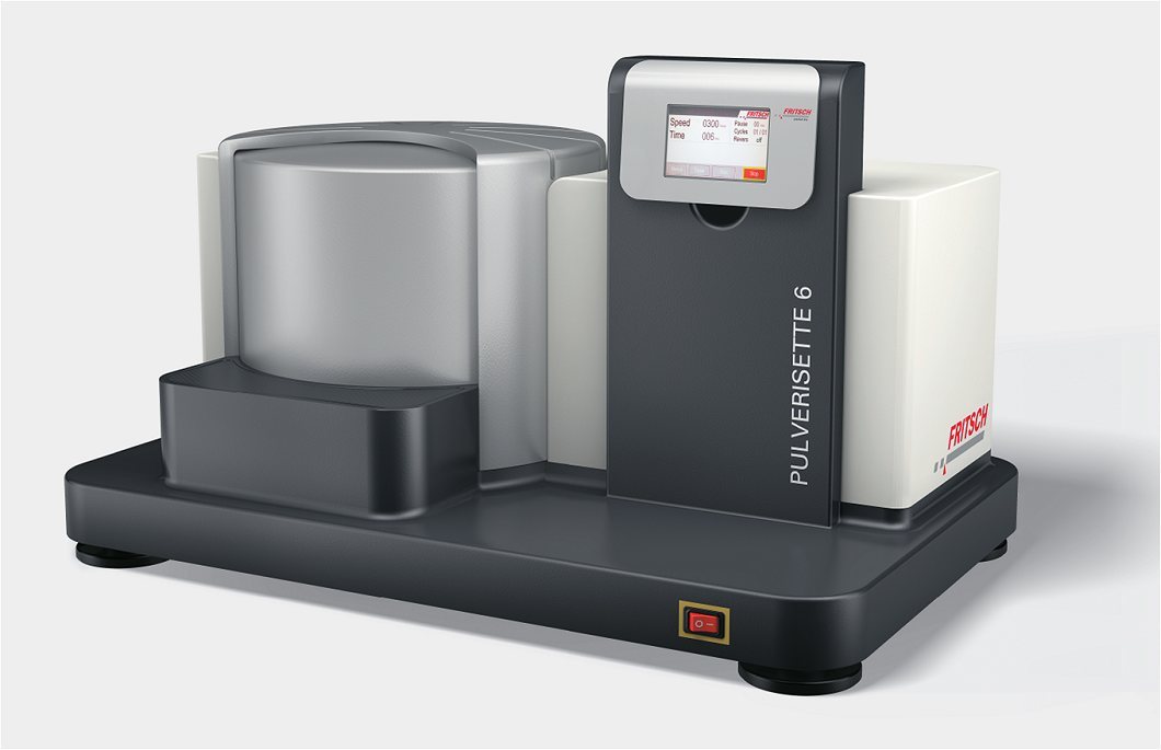
Journal ofALLOYSAND COMPOUNDSJournal of Alloys and Compounds 351 (2003) 119-125 120E. Botcharova et al. / Journal of Alloys and Compounds 351 (2003) 119-125 www.elsevier.com/locate/jallcom Supersaturated solid solution of niobium in copper by mechanical alloying E. Botcharovaa,*, M. Heilmaier, J. Freudenberger, G. Drew,, D. Kudashow, U. Martin , L. Schultz IFW Dresden, Institute for Metallic Materials, D-01171 Dresden, Germany Institute of Physical Metallurgy, Freiberg University of Mining and Technology, D-09596 Freiberg, Germany Received 4 July 2002; received in revised form 14 August 2002; accepted 14 August 2002 Abstract Alloys with both high strength and high conductivity have been produced by mechanical alloying. In the present study, copper wasmechanically alloyed with 5, 10 and 20 at.% Nb using a planetary ball mill. The Cu-Nb phase diagram shows a negligibly low mutualsolubility in the solid state, but high energy ball milling can largely extend the region of solid state solution. Previously, it was observedthat niobium partly dissolves in the copper lattice during milling. The present investigation demonstrates that this limit can be extended toa strongly supersaturated Cu solid solution ofup to 10 at.% Nb provided the appropriate mechanical alloying method is applied. Thechange in the powder microstructure was followed by scanning and transmission electron microscopy (TEM) as well as by X-raydiffraction (XRD) analysis. In the case of Cu-5%Nb and Cu-10%Nb a homogeneous single-phase microstructure was obtained after 30 hof milling. Elemental Nb could no more be detected, indicating the formation of a metastable supersaturated Cu-Nb solid solution.@ 2002 Elsevier Science B.V. All rights reserved. Keywords: Transition metal alloys; Mechanical alloying; Mechanical properties; Microstructure; Transmission electron microscopy 1. Introduction A common way of increasing the relatively low intrinsicstrength of copper while retaining its high electricalconductivity is alloying with different insoluble elementsto achieve particle strengthening. Potential alloying ele-ments can be found in the family of bcc elements (e.g. Cr,W, Ta, Nb, Mo,V) [1,2]. Among them the Cu-Nb alloyshave been reported to show the best mechanical properties[1]. In thermodynamic equilibrium the mutual solubility ofniobium and copper is negligibly small. Since their meltingpoints differ strongly, conventional cast metallurgy cannotbe applied on a large scale. On the other hand, alloys froman immiscible metal system can be manufactured by one ofthe following two techniques: rapid solidification (RS) andmechanical alloying (MA). By RS a fine distribution oftwo phases can be produced, but the formation of a highly ( *Corresponding author . Fax : +49-351-465-9320. ) ( E-mail address: e.botc h arova @i fw-dresd e n . de ( E. Botcharova).Present a ddress: U niversity of Cambridge, D epartment o f Materials S cience and M etallurgy, Cambridge C B2 3QZ, U K . ) supersaturated solid solution is usually not possible [3]. Incontrast, due to the high energy impact during milling, MAcan provide alloys with a good compositional and micro-structural homogeneity and a higher content of the alloyedelement in solid solution [3-8]. Previously, it has beenobserved that niobium dissolves partly in the copper latticeduring milling [4,5]. The present investigation demon-strates that this limit can be extended to a stronglysupersaturated Cu solid solution of up to 10 at.% Nbprovided the appropriate MA conditions are applied. 2. Experimental As starting material, high purity powders of copper andniobium with a particle size smaller than 35 um were used.Three compositions, namely Cu-5at.%Nb, Cu-10at.%Nband Cu-20at.%Nb were studied (in the following per-centages are always given as at.%). Thirty grams of thepowder mixture and 420 g of hardened steel balls with 10mm diameter were filled in each milling vial, corre-sponding to a powder-to-ball weight ratio of 1:14. MA wasperformed under an inert gas atmosphere (argon) in aRetsch planetary ball mill (PM 4000) at liquid nitrogen ( 0925-8388/02/$ -see front m atter r O 20 0 2 Elsevier Science B.V. All rights reserved.PII: S0925-8388(02)01025-3 ) temperature (77 K), using a rotational speed of 200 rev./min at a constant rotation direction. Milling was inter-rupted after every 30 min to cool down the vials in liquidnitrogen. After different milling times samples were takenfor microstructural investigations. In order to observe the change in microstructure duringmilling, the extracted powders were embedded in conduc-tive resin (Technovit 5000) and prepared by standardmetallographic techniques. The powders were examined byscanning electron microscopy (SEM) in a JEOL JSM 6400device and, for high-resolution SEM, in a LEO 1530. Insome cases, when a higher resolution was needed, trans-mission electron microscopy(TEM) was carried out in aJEOL JEM 2000 FX operating at 200 kV. X-ray diffractionpatterns were measured in a Philips diffractometer (PW1830) using filtered CoKa radiation (入=0.178897 nm).The mechanical properties of the powders were assessedusing a Vickers microhardness tester with a load of 245mN at a loading time of 10 s. The impurity content of thepowder after milling was determined by chemical analysis. 3. Results and discussion 3.1. Microstructural investigations 3.1.1. SEM During the milling process the microstructure of thepowder develops from a coarse lamellar type after 5 hmilling (Fig. 1a) over a fine lamellar microstructure at thelimit of SEM resolution (Fig. 1b) to a very homogeneousmicrostructure (Fig. 1c). Energy dispersive spectroscopy(EDX) analysis of the latter powder shows a correspondinghomogeneous distribution of the alloyed Nb. Only veryfew niobium particles with a size of about 100 nm remainafter milling. 3.1.2. TEM An investigation of the microstructure of the powderafter 35 h (Cu-5%Nb and Cu-10%Nb) and 17 h (Cu-20%Nb) milling time shows a very fine nanocrystalline (a) (b) (c) Fig. 1. SEM study showing the change in microstructure of Cu-10%Nb with mechanical alloying: (a) 4 h; (b) 10 h; and (c) 25 h. Fig. 2. TEM showing a very fine microstructure of powder Cu-5at.%Nb (a) and Cu-10at.%Nb (b) after 35 h of milling. grain structure (Fig.2). At comparable milling the micro-structure becomes finer with increasing niobium contenttimes. As proved by EDX analysis in the TEM, thecomposition of the powder is very homogeneous. Electrondiffraction of the Cu-5%Nb and Cu-10%Nb powdersdoes not show niobium reflections, but in the diffractionpattern of the Cu-20%Nb powder some residual niobiumreflections can be detected (Fig. 3). In conclusion, these investigations reveal the successful formation of a com-pletely supersaturated and, hence,metastable Cu-Nb solidsolution with nanocrystalline grain size by MA in Cu-5%Nb and Cu-10%Nb powder mixtures. In the case ofCu-20%Nb, the formation of a complete (single-phase)solid solution of niobium in copper could not be achieved.This might be due, either to the very high niobium contentof 20at.% or to the too short milling time of only 17 h. 3.2. X-ray investigations X-ray diffractometry of the mechanically alloyed pow-der confirms the change of the microstructure of thepowder during the milling process. With increasing millingtime (from 4 to 35 h) the diffraction pattern of the powdershows a remarkable line broadening and an intensityreduction (Fig. 4). In addition, after long milling times(>30 h), the niobium peaks are no longer detectable. Thisconfirms the conclusion drawn from the microstructuralinvestigations by SEM and TEM, that niobium is com-pletely dissolved within the copper lattice during milling.In the following, the X-ray diffraction data are evaluated todetermine the grain size, the internal strain and the latticeparameter of the copper solid solution. 3.2.1. Copper grain size and internal strain in copper Line broadening can be caused both by a small grainsize or/and by internal strain. The integral line width B isgiven by [9]: where 入 is the X-ray wavelength; 0 the Bragg angle; d thegrain size; e the internal strain; and K~1 the Scherrerconstant. In order to separate the two effects a quantitativeanalyse can be carried out by using a plot according to theWilliamson-Hall method [10]: In case of a linear dependence of B cos 0 on sin 0 theslope of the straight line corresponds to the contribution ofthe internal strain 2e and the intersection with the ordinate Fig. 4. X-ray powder diffraction patterns of Cu-5%Nb with mechanicalalloying. yields the contribution of the line broadening by the smallgrain size d. For a suitable interpretation of this plot the elasticanisotropy of copper must be considered [11]. For this theangular data are normalised using the directional Young’smodulus calculated from the elastic compliances, S, (tabu-lated e.g. in [12]). Young’s modulus E for cubic metals isgiven by: where l, m and n are the directional cosines of the Braggreflections with respect to the crystallographic axes [12]. To extract the contribution of the sample (B) from thetotal line broadening B. a Wagner relation was assumed: where B. is the instrumental line broadening [9,13,14]. The internal strain in copper (Fig.5) increases withincreasing milling time and increasing Nb content (com-pare the Cu-10%Nb with the Cu-5%Nb alloy). Both factscani be explained by the higher content of dissolvedniobium in the copper solid solution at the same state ofmilling. Fig. 6 shows the evolution of the copper grain sizeduring milling as evaluated from the XRD measurements.The prediction from the microscopic investigations con-cerning the formation of a nanocrystalline grain structurein the powder during the milling process can be confirmed.The copper grains after 35 h milling have a diameter ofabout 11 nm in the Cu-5%Nb alloy and 7 nm in theCu-10%Nb alloy. Thus, the copper grain size decreaseswith increasing niobium content in the solid solution. The formation of an extended solid solution of niobiumin the copper matrix can be explained by means of the Fig. 5. Internal strain with respect to alloying time for Cu-5%Nb andCu-10%Nb systems. Fig. 6. Copper grain size respect to alloying time for Cu-5%Nb andCu-10%Nb systems. dislocation solute-pumping mechanism introducedbySchwarz [15]. According to this model the dislocation coreacts as a pump for the solutes. Niobium atoms are largerthan copper atoms, therefore the lattice near the niobiumatoms is compressed and the dislocation situated in anexpended lattice. Thus the niobium atoms interact with thedislocations. The solutes diffuse along the dislocation linetwo times faster compared to that of the inner grain regionswithout any lattice defects. Thus niobium atoms canarrange in the form of chains along the dislocation linewithin the copper matrix. The stress in the powder particlesexceeds the flow stress of copper due to the impact of theballs and hence the dislocations start to glide. As theniobium solutes cannot move easily they will be leftbehind the dislocation line. The niobium atoms remain afew nanometer within the copper grain whereby the matrixis locally supersaturated. In order to achieve the supersatu-rated state in the whole volume, the grain size has to bereduced to the nanometer scale, too. This means that theachievement of the extended solid solution is closelyrelated to the formation of a nanocrystalline structure[6,16]. Furthermore, a high dislocation density is needed to achieve2asupersaturated solid solution. Therefore, ananocrystalline structure and a high density of dislocations(high internal strain) is present in the powder as indicatedby from the X-ray analysis. 3.2.2. Copper lattice parameter In order to pursue the dissolution of niobium in thecopper lattice, i.e. the formation of the copper-niobiumsolid solution, the copper lattice parameter a, was de-termined. For an accurate determination of a, the measureddata were refined by the RIETVELD method [17]. Fig. 7shows the dependence of the copper lattice parameter onmilling time. At the beginning of milling, a increases to amaximum of 0.36406 nm in the Cu-10%Nb alloy and0.36315 nm in the Cu-5%Nb alloy after 17 h milling. Onfurther milling a decrease of a to 0.36268 nm in theCu-10%Nb alloy and to 0.36224 nm in the Cu-5%Nbafter 35 h milling is observed. The dependence of thecopper lattice parameter on milling time can be explainedby the observed dissolution of niobium, which can beassumed to take place by a substitutional mechanism. Thisleads to an increase of the copper lattice parameter due tothe larger atomic radius of niobium compared to copper. The decrease of the copper lattice parameter after 17 hmilling time is difficult to rationalize. Several hypothesesare conceivable: first, precipitation of niobium from thesupersaturated solid solution may occur. However, theseprecipitates have to be so small that neither peaks in theXRD diagrams are visible nor direct observation in TEM ispossible. Another possibility is the formation of stackingfaults during intense milling. Copper is known to have alow stacking fault energy, hence, a high density of stackingfaults can be expected.Consequently, these stacking faultsmay cause a peak shift opposite to that caused by thedissolved niobium in copper [6]. However, our TEMinvestigation could not prove that a high density ofstacking faults exists in the mechanically alloyed powder.A third explanation for the reduction of the copper latticeparameter is related to the oxygen content of the powder. Fig. 7. Lattice parameter for copper with respect to alloying time for Cu-5%Nb and Cu-10%Nb systems. 3.2.3. Influence of the oxygen content of the powder onthe copper lattice parameter Although the powder handling occurs in a protectiveatmosphere, a contamination by oxygen during millingcannot be avoided completely. The oxygen content in thepowder increases constantly with increasing milling time(Fig. 8). Fig. 7 shows that the dependence ofthe copperlattice parameter on milling time varies strongly with theoxygen content of the powder. For a low oxygen contentthe copper lattice parameter in the powder increases moreslowly and decreases later. Considering the presence of oxygen in the powder, twoassumptions to explain the decrease of the copper latticeparameter at longer milling times can be taken intoaccount. First, a change of the dissolution mechanism ofoxygen after a certain saturation concentration might beconceivable. It can be assumed that only a limited amountof oxygen atoms may be dissolved on interstitial sites ofthe copper lattice because of their limited number. Furtheroxygen atoms have to occupy lattice sites according to thesubstitutional mechanism. This would lead to a strongdecrease of the lattice parameter due to the large differencein the atomic radii (atomic radius of oxygen being substan-tially smaller than that of copper). Thus, the simultaneousincrease of the copper lattice parameter due to the dissolu-tion of niobium in copper is compensated by the decreaseof the copper lattice parameter due to a substitutionaldissolution of oxygen. After 17 h milling the decrease ofthe copper lattice parameter even dominates due to thelarger difference in the atomic radii between copper andoxygen than between copper and niobium. The second assumption is the formation of niobiumoxide clusters. This would lead to a decrease of the latticeparameter of the copper matrix as niobium as well asoxygen are precipitated from the copper matrix. Thishypothesis is supported by the fact that the affinity tooxygen is much higher for niobium than that for copper.Consequently, the formation of niobium oxide is favouredover that of copper oxide. As the diffusivity of the atoms at Fig. 8. Contamination by oxygen in powder of Cu-5%Nb and Cu-10%Nb systems. Fig. 9. Microhardness of powder with milling time. the milling temperature is quite low, the distance betweenthe niobium and oxygen atoms has to be small enough inorder to form niobium oxide. This requirement is fulfilledonly up to certain concentrations of both elements in thecopper matrix. Hence niobium oxide clusters can onlyform at a later stage of milling. They gd?o nncot grow furtherdue to the absence of any driving force and they arethermodynamically stable. Due to their small size theclusters can neither be detected by X-ray diffraction, norby standard TEM investigations. However, proof of this hypothesis would require thepreparation of Cu-Nb powders with a substantially re-duced oxygen contamination which should not then exhibitthe lattice parameter reduction upon long milling times.This possibility will be examined in future investigations. 3.3. Microhardness measurements Fig. 9 shows the change of the microhardness during themilling process. First, the microhardness of the powderincreases strongly followed by an only moderate increaseafter 17 h of milling time. This corresponds exactly to themilling time dependence of the internal strain in copper(Fig. 7) as discussed previously. The microhardness showsvalues of about 450 HV in the Cu-5%Nb alloy and about500 HV in the Cu-10%Nb alloy. Obviously, the higherhardness values in the Cu-10%Nb alloy can be attributedto the higher amount of dissolved niobium in copper and tothe resulting larger internal strain in the solid solution. 4. Conclusions In contrast to previous studies [4,5] the present studydemonstrates a complete dissolution of niobium in thecopper lattice up to 10at.% Nb. MA results in a supersatu-rated solid solution of niobium in copper due to the highenergy impact during milling. The influence of oxygenimpurities on the formation of the supersaturated solidsolution by milling is not yet well understood. The resulting homogeneous Cu solid solution is nanocrystallinein nature with a (steady state) grain size of about 10 nm.Due to the dissolution of niobium in the copper matrix anddue to the strong plastic deformation exerted duringmilling the value of the internal strain in the powder isvery high. This results in an increase of the powderhardness to 500 HV. Acknowledgements This work was supported by the Bundesministerium furBildung und Forschung by grant no 03SC5DRE. References ( [1] D.G. M orris, M . A. Mo r ris, Me c hanical allo y ing of c o pp e r-b.c.c.element m ixtures, Scripta M etall. Mater. 2 4 (1990) 1 7 01-1 70 6. ) ( [2] L.G. Fritzemeier , Nanostruct. Mate r . 1 (1992)257-2 6 2. ) ( [3] A.N. P atel, S. Diamond, The e f fects o fnon-equilibrium processing in the development o f c opper alloys, M ater. Sci. Eng. 98 ( 1988)329- 3 34. ) ( [4] A . B enghalem, D . G. Mor r is, Structural evolution during intense ballmilling of copper-niobium mi xtures, Scripta M etall. Mater. 27 (1992) 739-744. ) ( [5] A. B enghalem, D.G. M o rris, Microstructure and m e chanical p r op- ) ( erties of concentrated copper - niobium a lloys prepared by me- chanical alloying, Mater. Sci. Eng. A161 ( 1993) 2 55-266. ) [6] C. Suryanaryana, Mechanical alloying and milling, Prog. Mater. Sci.46 (1-2)(2001)1. [7] J.S. Benjamin, Mechanical alloying, Sci. Am. 234 (1976) 40. [8] C.C. Koch, The synthesis and structure of nanocrystalline materialsby mechanical attrition: A review, Nanostruct. Mater. 2 (1993)109-129. [9] W.-M. Kuschke, R.-M. Keller, P. Grahle, R. Mason, E. Arzt,Mechanisms of powder milling investigated by X-ray diffraction andquantitative metallography, Z. Metallkde.86(12)(1995)804-813. [10] G.K. Williamson, W.H. Hall, X-ray line broadening from filedaluminium and wolfram, Acta Metall.1 (1953) 22-31. [11] A. Benghalem, D.G. Morris, Milling and mechanical alloying ofcopper and some solution alloys seen as a thermomechanicalprocess, Acta Metall. Mater. 42 (1994) 4071-4081. [12] G.E. Dieter, Mechanical Metallurgy, McGraw-Hill, UK, 1988, 58. ( [13] E . Tschegg, A. Wagendristel, P . S kalicky, ElektronenmikroskopischeUberprufung d e r r o ntgenographischen Linienbreitenanalyse n ac hHall, Z. Naturforsch. 28A (1973 ) 1735-1737. ) ( [14] C.N.J. Wagner, E . N . A qua, Analysis of the b roadening of powderpattern peaks from c old-worked f ace-centered and b ody-centered cubic m etals, Adv. X -ray Anal. 7 (1963) 4 6 -65. ) [15] R.B. Schwarz, Microscopic model for mechanical alloying, Mat.Sci. Forum 269-272 (1998) 665-674. [16] C. Suryanarayana, F.H. Froes, Nanocrystalline titanium-magnesiumalloys through mechanical alloying, J. Mater. Res. 5(9) (1990). [17] H. Krischner, B. Koppelhuber-Bitschau, Rontgenstrukturanalyse undRietveldmethode.Friedr.ViewegaandSohnVerlagGmbH.Braunschweig/Wiesbaden, 1994. 样品原始尺寸35um,3种混合比Cu-5at.%Nb, Cu-10at.%Nb和Cu-20at.%Nb。30g粉末混合物,420g10mm硬质钢研磨球,球料比(质量比)1:14。PM400研磨罐中加入惰性气体(氩气)保护。200转/分运行30分钟后用液氮降温,运行不等时间来做微观结构观察。
关闭-
1/7

-
2/7

还剩5页未读,是否继续阅读?
继续免费阅读全文产品配置单
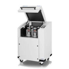
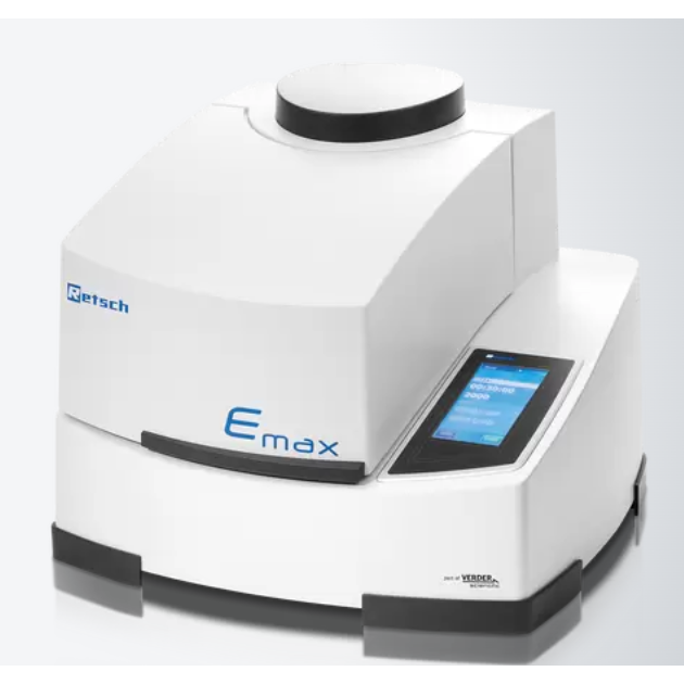
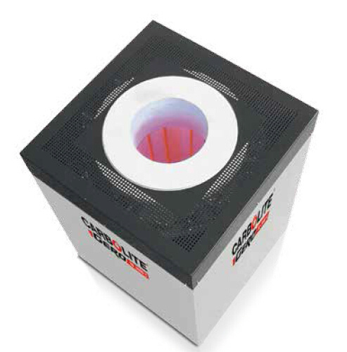
弗尔德(上海)仪器设备有限公司为您提供《铌铜中合金制备检测方案(研磨机)》,该方案主要用于合金中其他检测,参考标准《暂无》,《铌铜中合金制备检测方案(研磨机)》用到的仪器有德国莱驰行星式球磨仪/机Retsch PM400、德国莱驰高能球磨仪Retsch Emax、卡博莱特盖罗HTRV垂直管式炉 CarboliteGero。
我要纠错
推荐专场
研磨机、研磨仪、粉碎机、球磨机
更多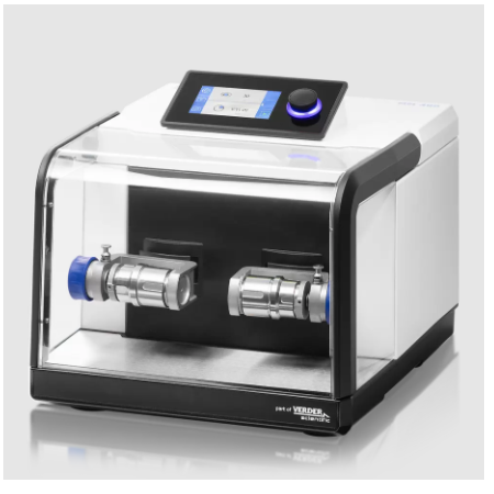

相关方案
 咨询
咨询