方案详情文
智能文字提取功能测试中
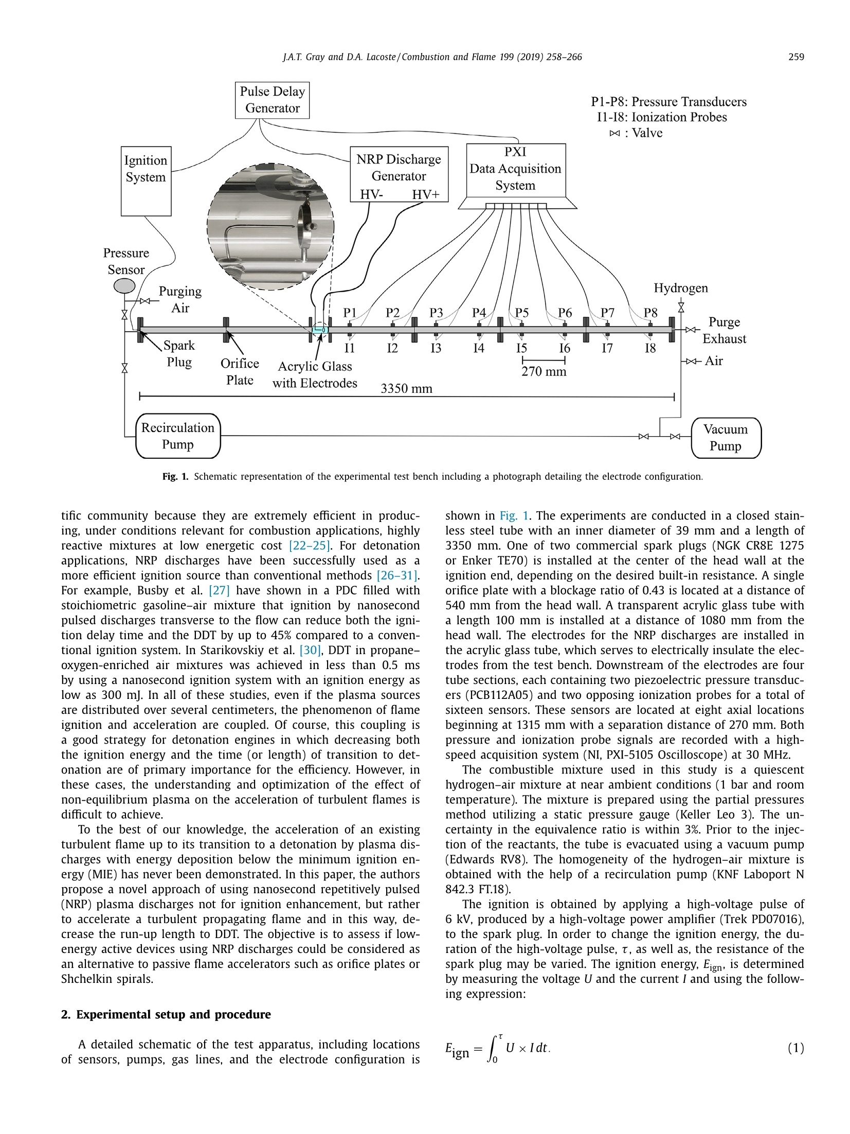
Combustion and Flame 199(2019) 258-266Contents lists available at ScienceDirect J.A.T. Gray and D.A. Lacoste/Combustion and Flame 199 (2019) 258-266259 https://doi.org/10.1016/j.combustflame.2018.10.0230010-2180/O 2018 The Combustion Institute. Published by Elsevier Inc. All rights reserved. Combustion and Flame ELSEVIER journal homepage: www.elsevier.com/locate/combustflame Enhancement of the transition to detonation of a turbulenthydrogen-air flame by nanosecond repetitively pulsed plasmadischarges Joshua A.T. Gray*, Deanna A. Lacoste King Abdullah University of Science and Technology (KAUST), Clean Combustion Research Center, Thuwal 23955-6900, Saudi Arabia ARTICLE INFO ABSTRAC T Article history:Received 30 May 2018Revised 20 July 2018Accepted 17 October 2018Available online 2 November 2018 Keywords:Deflagration-to-detonation transitionPlasma-assisted combustionNon-equilibrium plasmaFlame acceleration This work provides proof of concept for the use of nanosecond repetitively pulsed (NRP) plasma dis-charges to accelerate a propagating turbulent flame, resulting in enhanced deflagration-to-detonationtransition and significant reduction in run-up length. The investigations are conducted on a stoichiometrichydrogen-air mixture at near ambient conditions. The effect of plasma actuation on the flame velocity isinvestigated using time-of-flight measurements of the propagating flame and detonation wave. The flamevelocity shortly after the application of the NRP plasma discharges is more than double that obtained incases in which no plasma is applied. High-speed imaging of OH* chemiluminescence in the electrode areaconfirms this result and provides insight about the mechanisms of plasma action. While the volumetricenergy deposited during plasma actuation is sufficiently low as to not ignite the combustible mixtureprior the arrival of the flame, the chemical and thermal enhancement of the gas is efficient enough tosignificantly accelerate the transition to detonation. The decrease in the run-up length to transition todetonation is obtained for a plasma power of less than 0.14% of the thermal power of the flame. This re-sult indicates that low-energy active devices using NRP discharges might be suitable for replacing passivedevices such as orifice plates or Shchelkin spirals. 1. Introduction The need for more efficient cycles for combustion-based energyproduction has led to much attention being paid to pressure-gaincombustion cycles in recent years (e.g.,[1-6]). These cycles are in-herently more efficient and will allow not only for an easier tran-sition to but also, when utilizing hydrogen as a fuel, an efficientcoupling with renewable energy sources in the future [7-9]. Onesuch pressure-gain cycle is known as the Fickett-Jacobs cycle [10],which is based on the reaction of fuel and oxidizer by means of adetonation wave. The so-called pulse detonation combustor (PDC)is one concept that utilizes this thermodynamic cycle. Due to energetic considerations, however, the detonation is typ-ically not directly initiated, but rather the gaseous mixture is ig-nited by means of a low-energy source and the resulting flame isaccelerated until the phenomenon known as the deflagration-to-detonation transition (DDT) occurs [11]. Frequently, obstacles areused in order to induce DDT (e.g., [12-15]). However, both thenumber of these obstacles as well as the run-up length to the oc- ( * Corresponding author. ) ( E-mail address: j oshua.gray@kaust.edu.sa (J. A .T. Gray). ) currence of DDT have a direct impact on the efficiency of the PDC[16]. Furthermore, the obstacles may be subjected to extreme ther-mal loading and subsequent failure. For these reasons, it may beargued that limiting the number of obstacles or eliminating themaltogether for the purpose of inducing DDT is an enabling step forpulse detonation technologies. An alternative solution is the use of electrical discharges to de-crease the run-up length to DDT. Arc discharges have been success-fully used to enhance DDT [17,18], but the electrical energy depo-sition of these thermal plasmas is too high to consider them foran actuator that can be efficiently used in a PDC. For example, byusing a combination of several discharges, Frolov et al.[18] suc-cessfully reduced the electrical energy deposition necessary for theonset of a detonation down to 100 J, which remains a few ordersof magnitude higher than a conventional ignition system for gasturbines or car engines. In addition, the synchronization of suchdistributed arc discharges, each of them acting as a local ignitionsource, is extremely important and challenging. A non-optimizedsynchronization could induce adverse effects on the DDT [19]. On the other hand, non-equilibrium plasma producedbynanosecondrepetitively pulsedl (NRP) discharges hHasshownpromising results in plasma-assisted combustion [20,21]. TheseNRP discharges have aroused a strong interest from the scien- Fig. 1. Schematic representation of the experimental test bench including a photograph detailing the electrode configuration. tific community because they are extremely efficient in produc-ing, under conditions relevant for combustion applications, highlyreactive mixtures at low energetic cost [22-25]. For detonationapplications, NRP discharges have been successfully used as amore efficient ignition source than conventional methods [26-31].For example, Busby et al. [27] have shown in a PDC filled withstoichiometric gasoline-air mixture that ignition by nanosecondpulsed discharges transverse to the flow can reduce both the igni-tion delay time and the DDT by up to 45% compared to a conven-tional ignition system. In Starikovskiy et al. [30], DDT in propane-oxygen-enriched air mixtures was achieved in less than 0.5 msby using a nanosecond ignition system with an ignition energy aslow as 300 mj. In all of these studies, even if the plasma sourcesare distributed over several centimeters, the phenomenon of flameignition and acceleration are coupled. Of course, this coupling isa good strategy for detonation engines in which decreasing boththe ignition energy and the time (or length) of transition to det-onation are of primary importance for the efficiency. However, inthese cases, the understanding and optimization of the effect ofnon-equilibrium plasma on the acceleration of turbulent flames isdifficult to achieve. To the best of our knowledge, the acceleration of an existingturbulent flame up to its transition to a detonation by plasma dis-charges with energy deposition below the minimum ignition en-ergy(MIE) has never been demonstrated. In this paper, the authorspropose a novel approach of using nanosecond repetitively pulsed(NRP) plasma discharges not for ignition enhancement, but ratherto accelerate a turbulent propagating flame and in this way, de-crease the run-up length to DDT. The objective is to assess if low-energy active devices using NRP discharges could be considered asan alternative to passive flame accelerators such as orifice plates orShchelkin spirals. 2. Experimental setup and procedure A detailed schematic of the test apparatus, including locationsof sensors, pumps, gas lines, and the electrode configuration is shown in Fig. 1. The experiments are conducted in a closed stain-less steel tube with an inner diameter of 39 mm and a length of3350 mm. One of two commercial spark plugs (NGK CR8E 1275or Enker TE70) is installed at the center of the head wall at theignition end, depending on the desired built-in resistance. A singleorifice plate with a blockage ratio of 0.43 is located at a distance of540 mm from the head wall. A transparent acrylic glass tube witha length 100 mm is installed at a distance of 1080 mm from thehead wall. The electrodes for the NRP discharges are installed inthe acrylic glass tube, which serves to electrically insulate the elec-trodes from the test bench. Downstream of the electrodes are fourtube sections, each containing two piezoelectric pressure transduc-ers (PCB112A05) and two opposing ionization probes for a total ofsixteen sensors. These sensors are located at eight axial locationsbeginning at 1315 mm with a separation distance of 270 mm. Bothpressure and ionization probe signals are recorded with a high-speed acquisition system (NI, PXI-5105 Oscilloscope) at 30 MHz. The combustible mixture used in this study is a quiescenthydrogen-air mixture at near ambient conditions (1 bar and roomtemperature). The mixture is prepared using the partial pressuresmethod utilizing a static pressure gauge (Keller Leo 3). The un-certainty in the equivalence ratio is within 3%. Prior to the injec-tion of the reactants, the tube is evacuated using a vacuum pump(Edwards RV8). The homogeneity of the hydrogen-air mixture isobtained with the help of a recirculation pump (KNF Laboport N842.3 FT.18). The ignition is obtained by applying a high-voltage pulse of6 kV, produced by a high-voltage power amplifier (Trek PD07016),to the spark plug. In order to change the ignition energy, the du-ration of the high-voltage pulse, t, as well as, the resistance of thespark plug may be varied. The ignition energy, Eign, is determinedby measuring the voltage U and the current I and using the follow-ing expression: All voltages are measured with high-voltage probes (TektronixP6015A). The current is obtained by measuring the voltage dropacross a 50 shunt resistor (Kanthal 887AS500KDG) connectedin series with the spark plug on the ground side of the gap. Thespark plug gap distance is set to 1 mm. The three voltage signalsare recorded using a high-speed oscilloscope (Agilent DSO9254A). The NRP plasma discharges are produced by applying high-voltage pulses of 15 ns duration, at a repetition rate of 100 kHz.The maximum amplitude of the high-voltage pulses is 24.5 kV,produced by applying simultaneously a positive high-voltage pulseof 12.25 kV and a negative high-voltage pulse of -12.25 kV to theelectrodes with an NRP discharge generator (FID FPD 25-100MC2).The electrode configuration consists of a sharpened pin cathode(diameter 1.6 mm, radius of curvature of the tip of about 100 um)and a ring-shaped anode (inner diameter: 20 mm, outer diame-ter: 24 mm, thickness: 4 mm) held in place by three stainless steeldowel pins, which are press fit through the wall of the acrylicglass tube. The pin electrode is positioned so that the sharpenedtip is 5 mm upstream of the center point of the ring electrode,rather than being positioned in plane, resulting in a gap distanceof around 11.2 mm. Both electrodes are constructed out of stain-less steel. The voltage at the electrodes is measured using high-voltage probes (Tektronix P6015A); and the current is measuredusing a Pearson current monitor (Model 6585). All voltage and cur-rent signals are recorded with a high-speed oscilloscope (AgilentDSO9254A) at a sampling rate of 2.5 GHz. The NRP discharge energy, ENRp, is calculated analogously tothe ignition energy, with the exception that the pulse duration ismuch shorter and the voltage and current signals must be care-fully synchronized. This synchronization is realized by adjustingthe temporal offset between the current and voltage signals suchthat ENRp=0 mj for an applied pulse that does not induce break-down. The resulting uncertainty in the energy deposition for asingle pulse is ±100 p. For plasma actuation, bursts from 35to 150 NRP discharges have been used. The energy depositionby a burst of NRP discharges, Eburst(NRP), is obtained by summingthe energy of all individual pulses. The ignition, NRP dischargeactuation, and measurement diagnostics are synchronized usinga pulse/delay generator (Berkley Nucleonics Corporation, Model575). In order to ensure reproducible initial conditions, a careful ex-perimental procedure is followed for these experiments. Beforeeach experiment, the tube is purged with pressurized air for tenminutes in order to remove any excess water vapor from the previ-ous experiment. Subsequently, the volume is evacuated to 10 mbarusing the vacuum pump. Using partial pressures, the test bench isfilled with a stoichiometric hydrogen-air mixture up to a pressureof 1 bar. The hydrogen and air are then mixed for three minutesusing the recirculation pump, after which the mixture is given oneminute to settle before being ignited. This experimental procedureand its repeatability were verified over the course of more thanone hundred test runs before the NRP plasma experiments wereconducted. The propagation speed of the reaction front is deter-mined using the time-of-flight method from the ionization probesignals. An example of such signals as well as the pressure sig-nals at the same axial location is provided in Fig. 2. This exampleshows a steady-state detonation wave with a propagation veloc-ity near that of the Chapman-Jouguet (CJ) velocity of 1966 m/s.The primary source of uncertainty is due to the method of deter-mining the time of arrival of the reaction wave. The arrival timeis defined as the time at which the ionization probe signal dropsto 99% of its initial value. This allows for the arrival event to beclearly identified above the inherent noise of the data acquisitionsystem. Because the drop for a detonation wave is very steep, thisuncertainty is ±5 m/s. For the turbulent flame, the drop is moregradual leading to an uncertainty of ±50 m/s Summary of the five ignition conditions tested. The duration, t, of the ignition pulseand the built-in resistance of the spark plug control the ignition energy, Eign· Ignition condition 1 2 3 4 5 Spark plug resistance, k2 4.6 0 4.6 0 4.6 t, ms 1 2 4 Eign, mj 9 45 Finally, in order to visualize the effect of NRP discharges onthe flame propagation, the acrylic glass tube was replaced by aquartz glass tube of the same dimensions. The images are obtainedwith a high-speed CMOS camera (LaVision HSS8) coupled with anintensifier (LaVision IRO), a UV lens (105 mm F/5.6 Coastal Op-tics), and a 40-nm bandpass filter (LaVision 1108760) centered at320 nm, for selection of the OH* chemiluminescence of the flame.The frame rate of the camera is synchronized with the plasmapulses at one frame per pulse. The exposure time is 9 us. Notethat the light emission from the discharges is collected simulta-neously with the flame emission. Therefore, in the location of thedischarges the light emission is not only due to the OH(A-X) tran-sition but also to the N2(C-B) transition, excited nitrogen being oneof the main emitting species of non-equilibrium discharges in thisrange of wavelengths. 3. Results 3.1. Combustion front propagation without plasma actuation As expected for such low energies, the occurrence of DDT is notobserved for any of these ignition conditions. Furthermore, no ap-parent effect is evident on the initial flame propagation. In fact, thevariation due to the stochastic character of turbulent flame propa-gation significantly overshadows any possible effect that the igni-tion energy in the specified range of conditions may have on the Time,ms Fig. 2. Example waveforms obtained from piezoelectric pressure transducers and ionization probes at two axial positions. The positions for P6, P7, I6, and I7 are shown inFig. 1. These signals are used to obtain the time-of-flight for the reaction waves. A time of around 0.130 ms corresponds roughly to CJ velocity. Time, ms Fig. 3. Example of waveforms for voltage and total current as well as the corresponding calculated energy deposition for an ignition spark with a duration of t=1 ms. Theoscillations following the initial breakdown and plateau are due to a power limitation of the power supply. flame propagation. This is depicted for example test cases in Fig. 4.Notice that there are two modes of propagation regardless of ig-nition energy. One is characterized by extreme deceleration of theflame towards the end of the tube (dashed lines in Fig. 4). Thisis likely due to the “tulip flame"phenomenon, which is known toreadily occur in propagating flames in tubes [36].The other is char-acterized by the flame successfully resisting these oscillations andcontinuing to moderately accelerate to speeds of around 1000 m/s(solid lines in Fig. 4). On average, regardless of the ignition energy(in the range investigated), in about 60% of the cases, the flamedecelerates, while in 40% of the measurements, the flame acceler-ates. It is important to note that these tests are conducted with theelectrodes shown in Fig. 1 installed. Therefore, although there is noplasma actuation, the fluid dynamic effects on turbulence genera-tion, which also accelerate the flame, are identical to the tests withplasma actuation. 3.2. Combustion front propagation with NRP discharges Electrical measurements of the NRP plasma discharges duringflame actuation indicate that the discharges are in the NRP sparkregime [23]. However, for an applied voltage of 24.5 kV, occur- rence of weak and strong NRP sparks is observed. An example ofvoltage, total current, and energy deposition for a weak NRP sparkdischarge is shown in Fig. 5a. The weak NRP spark discharges ex-hibit a maximum current of around 27 A and energy depositionof around 1±0.1 mJ per pulse. Assuming a discharge diameter of0.8 mm and a discharge length of 11.2 mm, the energy density isthen about 0.178 J/(cm3bar). In contrast, the strong NRP sparksexhibit maximum currents in excess of 100 A. The energy per pulseis then around 11±0.2 mJ (1.96 J/(cmbar)), approaching the de-sign maximum energy per pulse for the power supply of 12 mj.An example of voltage, total current, and energy deposition for astrong NRP spark discharge is shown in Fig. 5b. When a burst of pulses is applied, the initial pulses always be-gin in the weak spark regime and at some point, they may transi-tion to the strong sparks. This may occur as early as pulse 20-30or may not occur at all. If the strong NRP spark regime occurs tooearly, it may ignite the mixture independently and disrupt the ac-celeration of the flame. In addition, for a given number of pulses,it will drastically increase the energy deposition. For these reasons,the occurrence of strong NRP sparks must be controlled and, ifpossible, avoided. In order to do so, the total voltage between theelectrodes is limited to 24.5 kV. In addition, as the probability of Position, m Fig.4. Development of the reaction front propagation speed obtained from time-of-flight measurements using ionization probes for cases with varying ignition energieswith no NRP plasma discharges. The uncertainty in these velocity measurements is ±50 m/s. -Current-Voltage--Energy Fig. 5. Example of synchronized voltage and total current signals measured during a flame acceleration event and the corresponding energy deposition (a) for a single weakNRP spark (the insert presents the energy deposition during a burst of 35 pulses for which all of the individual pulses are weak NRP sparks), and (b) for a single strong NRPspark. Position, m Table 2 Summary of the conditions of NRP discharge actuation tested. For all of these con-ditions, the applied voltage is 24.5 kV, the pulse repetition frequency is 100 kHz,and the energy of the ignition spark is 9 mj. Number of pulses 150 100 35 Duration of plasma actuation, ms 1.5 1 0.35 Minimum observed Eburst(NRP), mJ 150 100 35 Fburst(NRP)+Fign,m 159 109 44 the transition to the strong NRP sparks increases with the numberof pulses, decreasing the number of pulses should also be consid-ered. Table 2 summarizes the different conditions of NRP dischargeactuation that have been evaluated in this study. Careful timing between ignition and plasma actuation is neces-sary. In order to observe the maximum effect on the combustionfront propagation speed, NRP discharges must be applied whenthe flame is in the vicinity of the electrodes. Applying the burst ofNRP discharges too long before or after the flame passes throughthe electrode assembly results in no effect on the flame accelera-tion. As it can be observed in Fig. 4, the speed of the flame canvary from 200 to 700 m/s when it enters the measurement sec-tion. Based on the time of arrival of the flame at the first ion-ization probe and its propagation speed at this location, it is es-timated that the flame consistently arrives at the electrodes at be-tween 11.5 ms and 12.5 ms after ignition. For a pulse train of 150pulse at a repetition frequency of 100 kHz and beginning the NRPpulses after a delay of 11 ms after ignition ensures repeatable DDT.Systematically increasing the delay and decreasing the number ofpulses allows for DDT to be achieved with as little as 35 pulses.Due to the jitter in the arrival of the flame front, however, reduc-ing the number of pulses has a direct impact on the repeatabilityof the experiments. The effect of plasma actuation obtained for a burst of 100pulses and for a delay between the ignition and the plasma ac-tuation of 11 ms is presented in Fig. 6, along with cases for noplasma actuation. Plasma actuation consistently results in the oc-currence of DDT. In order to confirm the reliability of using theseNRP plasma discharges in accelerating DDT, a series of twenty testruns alternating between plasma actuation and no plasma actua-tion were conducted using an ignition energy of 9 mj. In the caseof no plasma actuation, DDT was never observed. In eight of tencases, the flame exhibited the aforementioned extreme decelera-tion. This number is slightly higher than the 60% of decelerating flames observed for the investigation of the effect of ignition en-ergy (see Section 3.1). This is probably due to the limited numberof tests. In the cases with NRP discharge actuation, a significant ef-fect is observed on the flame acceleration and DDT occurred in allcases. The flame velocity observed between the second and thirdionization probes is already more than double that of the testswithout plasma. Figure 7 compares the reaction front propagation speeds ob-tained for plasma actuation with 150 (blue), 100 (red) and 35(black) pulses. For the three cases, DDT occurs at about 3 m. Theeffect of the NRP discharges seems to be not strongly correlatedto the number of pulses. However, as it can be noticed in Fig.6,where 10 tests performed with a burst of 100 pulses are depicted,that the variation in the acceleration of the flame front can belarge. For example, in five cases the transition to detonation hasalready occurred at 2.5 m, while for the other five cases, the prop-agation speed is less than 1500 m/s. Further investigation will beneeded to make any conclusion about the effect of the number ofpulses on the flame acceleration. During the course of these experiments, it was determined thatit is possible of obtain DDT with only a train of 35 weak discharges(as shown in Fig. 5a). However, it is important to emphasize thefact that successful synchronization of such a train is very diffi-cult. The typical course of events is that the pulses begin as weakdischarges in the fresh gases and as the flame enters the inter-electrode area, the discharge transitions to the strong regime dueto the change in the reduced electric field. For example, the im-ages shown in Fig. 8 correspond to one such case. Only if thepulses are stopped before the flame enters the inter-electrode area,can DDT be obtained without strong discharges. The maximum al-lowable time delay between ceasing of the discharge pulses andflame arrival is not yet known, but from our preliminary results, itshould be on the order of a few hundred microseconds. Due to thestochastic nature of the flame, this parameter has not been inves-tigated in the current setup. These tests establish proof of concept for using NRP plasma dis-charges in enhancing flame acceleration and decreasing DDT run-up length. Furthermore, this may be accomplished only with dis-charges in the weak spark regime if the last pulse occurs shortlybefore the flame arrives. For this case, the total required energyfor successful DDT, the sum of the ignition spark and the 35 NRPspark discharges, is around 44 mJ (see Figs. 3 and 5). However,it is important to note that synchronization is difficult without atriggering scheme due to the stochastic nature of the flame prop-agation. Conseqa9uently, using only 35 pulses may result in no DDTif the necessary conditions are not met. Nevertheless, keeping inmind that transition to detonation could not be observed for anignition energy up to 70 mj, this strategy of flame acceleration byNRP discharges could be energetically more efficient than increas-ing the energy of the ignition source. 4. Discussion The effect of plasma actuation on DDT is assessed by apply-ing a burst of NRP discharges synchronized with the propagationof a stoichiometric hydrogen-air flame in the inter-electrode area.The stochastic nature of the flame propagation leads invariably tothe first pulses being applied in the fresh mixture. The followingpulses may be applied to the flame itself or even in the burntgases. Due to the strong shot-to-shot jitter in the flame propa-gation speed, it is difficult to predetermine how many of thesepulses will be applied to each of these domains. It is possible todetermine this a posteriori by using a high-speed visualization sys- tem such as an intensified camera with a frame rate of at least100 kHz. Based on the example presented in Fig. 8, where it isshown that about 15 discharges are generated in the fresh gases,about 5 discharges in the flame front, and the remaining 15 in theburnt gases, it is worthwhile to discuss what their relative effecton the flame acceleration could be. The pulses applied ahead of the flame front do not ignite thehydrogen-air mixture. This is visible in Fig. 8a and b, and in addi-tion, it has been verified that applying a burst of 35 pulses to thefresh mixture, for which no ignition source was used (Eion=0 m),did not ignite the mixture. The pulses either do not lead to thebreakdown of the mixture or produce weak NRP sparks with anenergy of ENRp=1 mj, which are too weak to ignite the mixture.The measured ENRp is significantly higher than the minimum ig-nition energy (MIE) for such a mixture, which is around 0. mJfor a gap distance of 3 mm, as measured by Ono et al.[37]. How-ever, when extrapolating their results to a gap distance of 11.2 mm,the MIE would then be 0.373 mJ. Furthermore, it is very commonfor mixtures not to ignite for energies up to three times the MIE(i.e., 1.1 mJ [37]), for non-optimized geometry and material of theelectrodes. If the weak NRP discharges applied to the fresh com-bustible mixture are not able to ignite a flame, they can neverthe-less have a strong local thermal and chemical impact on the freshgases, as shown in pure air, for example in [25,38]. The NRP sparkdischarges are known to heat the gas in an ultra-fast manner (afew tens of nanoseconds), up to a few thousands of kelvin, andto dissociate up to 50% of the oxygen [24]. In the present study,the thermal and chemical impact of the weak NRP sparks is prob-ably less than the maximum values measured in air. Nevertheless,the weak NRP sparks produced in the fresh gases should locallyincrease the combustion rate, increasing the wrinkling of the tur-bulent flame, and globally accelerating the combustion front. a) Pulse 10 zoom of cathode Fig. 8. High-speed OH*-chemiluminescence images of the interaction between aturbulent propagating hydrogen-air flame and NRP plasma discharges. In the firstimage, the geometry of the electrodes is presented as well as a close-up of a weakdischarge at the tip of the cathode (further enlarged and intensified). The pulses applied in the burnt gases may also have an impacton the acceleration of the flame. As it can been seen in Fig. 8dand e, the discharges produced can be intense. The NRP dischargesshould then result in a significant ultra-fast gas heating that willinduce the propagation of shock and pressure waves [41], whichpropagate into both the fresh gases and the burnt gases. Therefore,the phenomenon of shock-flame interaction could have a signifi-cant impact on the flame acceleration. When the shock waves pro-duced by the discharges interact with the flame, it can result ina wrinkling of the flame due to the Richtmyer-Meshkov instabil-ity. This phenomenon is due to the impulsive acceleration of the relatively discontinuous interface between the unburnt and burntgases. In contrast to the Rayleigh-Taylor instability, which is re-sponsible for the “tulip flame,” the Richtmyer-Meshkov instabil-ity is unstable in both directions [42]. In other words, it is irrele-vant whether the shock waves from the discharge travel upstreamthrough the fresh gases to meet the flame or downstream throughthe burnt gases to meet the flame. This means that every indi-vidual discharge that is strong enough to generate a shock wavehas the potential of increasing flame wrinkling. The cumulative ef-fect of several discharges may significantly enhance the combustion through flame wrinkling alone even for relatively weak in-dividual shock waves. This effect has been observed by Thomaset al. [43] for a single shock wave. For strong incident shockwaves, they observed DDT shortly after the shock interacted witha spherically expanding flame. Although the shock wave was muchstronger and the flame much slower than in the present work, theshock-flame interaction may also contribute to the observed flameacceleration induced by NRP discharge actuation. Finally, it is interesting to compare the electrical power of theplasma actuation with the thermal power of the flame. The aver-age electrical power applied during NRP discharge actuation canbe obtained by multiplying the energy deposition during a singlepulse by the number of pulses during a second. As the pulse rep-etition frequency is fixed at 100 kHz, the average plasma power isin the range from 100 W, for the weak NRP sparks, to 1.1 kW, forthe strong NRP sparks. Considering the initial conditions (stoichio-metric hydrogen-air mixture at 1 bar and room temperature), thelower heating value of hydrogen (120 MJ/kg), and the diameter ofthe tube, the heat release of the flame per unit length is 3.44 kj/m.When the flame enters the inter-electrode area, its velocity is typ-ically in the range of 200-700 m/s (see Fig. 4). Consequently, thethermal power of the flame in the plasma area is in the range of862 kW-2.4 MW. Thus, the percentage of NRP discharge electricalpower with respect to the thermal power of the flame is in therange of 0.004-0.14%. These values are more than one order of magnitude lower thanthe usual ratio of plasma power to flame thermal power that isused for enhancing flame properties, such as decreasing the leanblow-off limit [44], or controlling thermoacoustic instabilities [45].The main difference is that in all of these previous studies, theflames were stabilized and not freely propagating. In fact, freelypropagating flames are usually more sensitive to small perturba-tions than stabilized flames. The necessary run-up length to DDTfor practical PDC applications, however, is significantly lower thanwhat has been obtained in this study. In order to achieve suchlengths, it is likely that the electrical power of the NRP dischargesmust be higher. Nevertheless, a plasma actuator using NRP dis-charges might be a realistic alternative to passive flame acceler-ators. 5. Conclusions Proof of concept has been achieved for the use of NRP dis-charges during the flame acceleration phase in order to achieve asignificantly decreased run-up length to DDT. These findings havebeen obtained using time-of-flight measurements. The energy de-position of both the ignition spark and the NRP discharges havebeen quantified. Increasing only the ignition energy from 9 mJ to70 mJ results in no observable effect on the flame acceleration.However, using a low-energy spark ignition (9 mJ) in combina-tion with a properly-timed train of 35 NRP discharges results insignificant flame acceleration and subsequent DDT for an electri-cal energy as low as 44 mJ. This decrease in the run-up lengthto DDT is obtained for a plasma power of less than 0.14% of thethermal power of the flame. High-speed visualization of the flameOH* chemiluminescence shows that just after plasma actuation, the flame propagates two times faster than before plasma actu-ation. Further study will be necessary in order to determine themain mechanisms of the effect of the NRP discharges on the flameacceleration. Nevertheless, this strategy presents not only a moreenergetically efficient alternative to simply increasing the energydeposition in the ignition spark, but also a promising strategy forreducing or replacing obstacles in pulse detonation applications. Acknowledgements This work is funded by the Center of Competitive Funding fromKing Abdullah University of Science and Technology (Grant Num-ber 1975). References ( [1] R. Zitoun , D . Desbordes, Prop u lsiv e p e rformances of pulse d detonations, Com- b ust. S ci. Te c hnol . 144 ( 1 -6)( 1 999) 93-1 1 4. ) [2] D. Paxson, T. Kaemming, Influence of unsteadiness on the analysis of pressure ( gai n c ombustion d e vices, J. Propuls . Power 3 0 (2) (2014 ) 377-383. ) ( [3] S . F r olov, V . A k s enov, V . I v anov, Ex p erimental p r oo f o f Z e l'dovich cycle effi-ci e ncy g a i n over cyc l e wit h constant p ressur e combus t ion f or hydro ge n-oxygen fuel mixture, Int.J . Hydrogen E nergy 4 0 ( 2 1)(2015) 6 970-6975. ) ( [ 4] J . Gray, J . Vinkeloe, C. Paschereit, P . Stathopo u los, P . Berndt , R. Klein, T he r mody- n amic evaluation of pulse detonation combust io n f o r gas turbine power cyc l es, ASME Turbo Expo (2016). ) ( [5] R . B lackburn, R . M iller, T he Rayleigh e f ficiency o f p r e s sure ga i n co m bustors, J. Propuls. Power 3 3 (1) ( 201 7 ) 5 1 - 6 1. ) [6]J. Lisanti, W. Roberts, Pulse combustor driven pressure gain combustion forhigh efficiency gas turbine engines, in: A. Agarwal (Ed.), Combustion for PowerGeneration and Transportation., Springer, Singapore, 2017. [7] T.Jacobsson, V.Fjallstrom, M. Edoff, T. Edvinsson, CIGS based devices for solarhydrogen production spanning from PEC-cells to PV-electrolyzers: A compari-son of efficiency, stability and device topology, Solar Energy Mater. Solar Cells134(2015)185-193. [8]D. Zhao, C. Yang, Recent advances in the tio2/cds nanocomposite used for pho-tocatalytic hydrogen production and quantum-dot-sensitized solar cells, Re-new. Sustain. Energy Rev. 54 (2016)1048-1059. ( [9] D . Ferrero, M . S a ntarelli, I nvestigation of a n ovel c oncept f o r h y dr og en pr o -duction b y PE M wa t er electrolysis in t egrated wi t h mul t i- ju nct i on sol a r cel l s, Ene r gy Conve r s. M anag. 14 8 (2017) 16 - 29. ) ( [10] W. F ickett , W. Davis, Detonation T h eory and Experi m ent, C ha p ter 2 , Dover, Mi- neola , New York, 2001. ) ( [11] J . Le e , The De t onation P henome n on, Ch a pter 8, C a mbrid ge Univer s i t y Pr e ss , UK ,2008. ) ( [ 12] J. Lee, R. Knystautas, C . Chan, T u rbulent flame p rop a gation in o b s t a cle-filled tubes, Symp. (Int . ) Combust. 2 0 (1 9 85) 1 6 63-167 2 . ) ( [ 1 3] F . Schauer, J . Stutrud, R. Bradley, Detonation i n it i ation studies a n d performance results fo r pulsed detonation engine applications, 39th AI A A A erospace S c i- ences M e e ting a n d E x hibit ( 2 001). ) ( [ 1 4] G. Ciccarre l i , S . Dorofeev , Fl a me accleration and t ransition to detonat i on i n ducts, Progr. Energy Combust. Sc i. 34(4)(200 8 )499-550 . ) ( [15] R . S carpa, E . S truder, B. Cariteau, S . Kudriakov , N . Chaumeix, I R a bsorpti o n measurements of t h e v e locit y o f a p r emixed hy d rogen/air f lame pro p agati ng in a o b stacle-laden tube, 26th Internat i onal Co l loqu i um o n t he Dynami c s of E xplosions a nd React i v e S ystems ( 2 017 ) . ) ( [16] D . P axson, T . K aemmin g , Pe r fo r mance impa c t of d eflagrat i on to detonation t ransition enha n cing o bstacles, 37th AIAA Aerospace S ciences M eeting and E x - hibit (2009). ) ( [17] S . Frolov, V. B ase v i c h, V . A ksenov, S. Po l ikhov, De t o na t ion init i at i on by con- t rolled t riggering of e lectric d ischarges, J . P ropul s . P ower 1 9 (4 ) (2 0 03) 573-580. ) 00.[18] S. Frolov, V.Basevich, V. Aksenov, S. Polikhov, Optimization study of spray det-onation initiation by electric discharges, Shock Waves 14 (3) (2005) 175-186. ( [ 1 9] V. Kamenskihs, J . L ee, E ffect of an a xial electric fiel d on de t onation waves, Combust. F lame 1 5 9 (20 1 2)2 9 67-2 9 73. ) [20] S. Starikovskaia, Plasma assisted ignition and combustion, J. Phys. D: Appl.Phys. 39 (2006) R265-R299. [21Y]. Ju, W. Sun, Plasma assisted combustion: dynamics and chemistry, Progr. En-ergy Combust. Sci. 48 (2015) 21-83. .[221D. Pai, G.Stancu, D. Lacoste, C. Laux, Nanosecond repetitively pulsed dischargesin air at atmospheric pressure - the glow regime, Plasma Sources Sci. Technol.18 (2009).045030(7pp). [23]D1. Pai, D. Lacoste, C. Laux, Nanosecond repetitively pulsed discharges in airat atmospheric pressure -the spark regime, Plasma Sources Sci. Technol. 19(2010).065015(10pp). [24]G. Stancu, F. Kaddouri, D. Lacoste, C. Laux, Atmospheric pressure plasmadiagnostics by OES, CRDS and TALIF, J. Phys. D: Appl. Phys. 43 ((2010).124002(10pp). [25]D. Rusterholtz, D. Lacoste, G. Stancu, D. Pai, C. Laux, Ultrafast heating and oxy-gen dissociation in atmospheric pressure air by nanosecond repetitively pulseddischarges, J. Phys. D: Appl. Phys. 46 (2013). 464010(21pp). [26]V.Zhukov, A. Starikovskii, Effect of a nanosecond gas discharge on deflagrationto detonation transition, Combust. Explos. Shock Waves 42 (2) (2006) 195-204. [27]K. Busby,J. Corrigan, S. Yu, S. Williams, C. Carter, F. Schauer,J. Hoke, C. Cathey,M. Gundersen, Effects of corona, spark and surface discharges on ignition delayand deflagration-to-detonation times in pulsed detonation engines, 45th AIAAAerospace Sciences Meeting and Exhibit(2007).IL(200J [28A]. Rakitin, A. Starikovskii, Mechanisms of deflagration-to-detonation transitionunder initiation by high-voltage nanosecond discharges, Combust. Flame 155(1-2)(2008) 343-355. [29]V1. Zhukov, A. Rakitin, A. Starikovskii, Effect of high-voltage pulsed dischargeson deflagration to detonation transition, J. Propuls. Power 24 (1) (2008) 88-93. A. Starikovskiy, N. Aleksandrov, A. Rakitin, Plasma-assisted ignition and defla-gration-to-detonation transition, Phil. Trans. R. Soc. A 370 (2012) 740-773. J. Lefkowitz, P. Guo, T. Ombrello, S. Won, C. Stevens, J. Hoke, F. Schauer,Y. Ju, Schlieren imaging and pulsed detonation engine testing of ignition bya nanosecond repetitively pulsed discharge, Combust. Flame 162 (6) (2015)2496-2507. [32]Y.Raizer, Gas Discharge Physics, Chapter 10, Springer, Berlin, Heidelberg, 1991.331D. Ballal, A. Lefebvre, Influence of spark discharge characteristics on minimum ignition energy in flowing gases, Combust. Flame 24(1)(1975) 99-108. [34]S. sShohyn, eCn. eLrieuy,w W.. sShhimh.,n gI ganoitmi ona transition in turbulent premixed combustion,Combust. Flame 157 (2010) 341-350. [35]Q. Zhang, W. Li, S. Zhang, Effects of spark duration on minimum ignition en-ergy for methane/air mixture, Process Safety Progr. 30 (2) (2011) 154-156. 36]C. Clanet, G. Searby, On the tulip flame phenomenon, Combust. Flame 105(1996)225-238. [37]R. Ono, M. Nifuku, S. Fujiwara, S. Horoguchi, T. Oda, Minimum ignition energyof hydrogen-air mixture: Effects of humidity and spark duration, J. Electrostat.65(2007)87-93. [38A]. Lo, A. Cessou, P. Boubert, P. Vervisch, Space and time analysis of thenanosecond scale discharges in atmospheric pressure air: I. Gas temperatureand vibrational distribution function of N2 and O2, J. Phys. D: Appl. Phys. 47(11)(2014)115201. [39]W.Nighan, Electron energy distributions and collision rates in electrically ex-ciCted N, Co, and CO, Phvs. Rev. A 2 (5)(1970) 1989-2000. 40N. Aleksandrov, F. Vysikailo, R. Islamov, I. Kochetov, A. Napartovich, V. Pevgov,Electron-distribution function in 4:1 N2-02 mixture, High Temp. 19 (1)(1981)17-21. [41]D1. Xu, D. Lacoste, D. Rusterholtz, P. Elias, G. Stancu, C. Laux, Experimental studyof the hydrodynamic expansion following a nanosecond repetitively pulseddischarge in air, Appl. Phys. Lett. 99 (2011) 121502. [42]R1. Krechetnikov, Rayleigh-Taylor and Richtmyer-Meshkov instabilities of flatand curved interfaces, J. Fluid Mech. 625 (2009) 387-410. [43]G. Thomas, R. Bambrey,C. Brown, Experimental observations of flame acceler-ation and transition to detonation following shock-flame interaction, Combust.Theory Model. 5 (2001) 573-594. [44]G. Pilla, D. Galley, D. Lacoste, F. Lacas, D. Veynante, C. Laux, Stabilization of aturbulent premixed flame using a nanosecond repetitively pulsed plasma, IEEETrans. Plasma Sci. 34 (6) (2006)2471-2477. ( [45] J . Moeck, D . L acoste, C . Laux, C. Paschereit, Control o f co m bustion d y n amics in a s wirl-stabilized com b ustor w i th nanosecond rep e titiv el y pulsed dis c h arges, 51st AIAA Aeros p ace Sciences Mee ti ng in c lu d in g The New Horizons Forum and Aer o space Exposition (201 3 ). ) This work provides proof of concept for the use of nanosecond repetitively pulsed (NRP) plasma discharges to accelerate a propagating turbulent flame, resulting in enhanced deflagration-to-detonation transition and significant reduction in run-up length. The investigations are conducted on a stoichiometric hydrogen-air mixture at near ambient conditions. The effect of plasma actuation on the flame velocity is investigated using time-of-flight measurements of the propagating flame and detonation wave. The flame velocity shortly after the application of the NRP plasma discharges is more than double that obtained in cases in which no plasma is applied. High-speed imaging of OH ∗chemiluminescence in the electrode area confirms this result and provides insight about the mechanisms of plasma action. While the volumetric energy deposited during plasma actuation is sufficiently low as to not ignite the combustible mixture prior the arrival of the flame, the chemical and thermal enhancement of the gas is efficient enough to significantly accelerate the transition to detonation. The decrease in the run-up length to transition to detonation is obtained for a plasma power of less than 0.14% of the thermal power of the flame. This result indicates that low-energy active devices using NRP discharges might be suitable for replacing passive devices such as orifice plates or Shchelkin spirals.
关闭-
1/9
-
2/9
还剩7页未读,是否继续阅读?
继续免费阅读全文产品配置单


北京欧兰科技发展有限公司为您提供《氢-空气火焰中OH自由基的自发荧光检测方案(气体流量计)》,该方案主要用于太阳能中OH自由基的自发荧光检测,参考标准《暂无》,《氢-空气火焰中OH自由基的自发荧光检测方案(气体流量计)》用到的仪器有PLIF平面激光诱导荧光火焰燃烧检测系统、德国LaVision PIV/PLIF粒子成像测速场仪、LaVision IRO 图像增强器、LaVision DaVis 智能成像软件平台。
我要纠错
推荐专场


CCD相机/影像CCD
更多


相关方案
 咨询
咨询