方案详情文
智能文字提取功能测试中
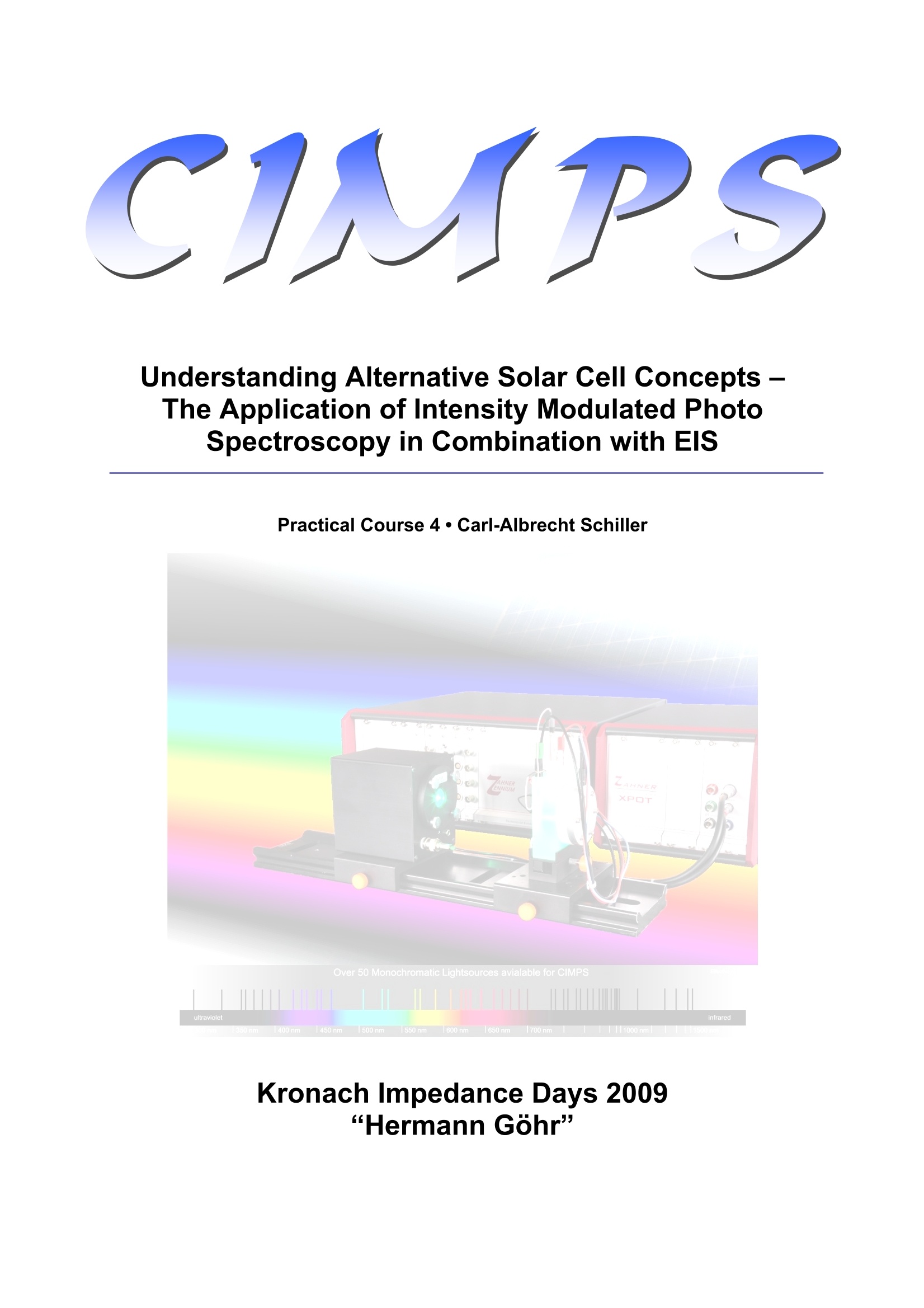
KIT 2009 - Hermann Gohr-CIMPS PS Understanding Alternative Solar Cell Concepts -The Application of Intensity Modulated PhotoSpectroscopy in Combination with ElS Practical Course 4·Carl-Albrecht Schiller Kronach Impedance Days 2009“Hermann Gohr General Light induced process一Ses like photosynthesis are of fundamental significance in theworld. In technique, the “photo-electric effect”occurring at illuminated interfaces likesemiconductor junction barriers is of great importance. Here, the electric potentialand the current flowing at the interface site, are depending on the illumination. Lightintensity with photo-voltage on the one hand and with photo-current on the otherhand are building two typical force-response couples for a dynamic transfer functionanalysis. Like the analysis of the impedance transfer function in the ElS, the IntensityModulated Photo Spectroscopy can help understanding the complex systems, inparticular when photo-electric effects are playing a significant role. Aim of the experiment CIMPS is based on the idea of the dynamic analysis of the photo-effect by means ofsmall-signal linear sinusoidal modulation technique. The CIMPS experiment shalldemonstrate, how the two frequency domain transfer functions photo-voltage efficiency = photo-voltage/ intensityand photo-current efficiency = photo-current/intensity can be determined by the application of modulated light with swept frequency on anelectrochemical cell containing a light-sensitive object. The meaning and the general0behaviour of both transfer functions shall be explained, together with1thecorresponding EIS. The importance of a stable, controlled intensity together with highmodulation linearity during the whole experiment shall be emphasized (the reason forthe name“CIMPS”=Controlled Intensity Modulated Photo Spectroscopy). The typical dynamic response of an ideal semiconductor barrier junction will bediscussed. Starting from that, the effects, limiting the photo-efficiency of alternativetechnique solar cells can be identified in the transfer function and their appearanceand properties can be interpreted. Test procedure One of two different experimental set-ups will be demonstrated dependent on theavailability. The first one is based on a photosensitive semi-conducting oxide layer,the second on the popular Graetzel-type solar cell. For the first experiment, an electrochemical cell with a light inlet at the spiral Pt-counter electrode (Photo-Electro-Chemical Cell =“PECC") is equipped with an Ag-AgCl reference electrode and an 0.5m NaNO3 aqueous electrolyte. A square Femetal sheet (~ 2 cm²) which was tempered some minutes at~ 600C to form ahematite-type oxide layer, acts as working electrode sample. A potentiostatic EIS(100KHz to 0.1Hz, starting at 1KHz, 5mV amplitude) is recorded at the OCP underdarkness. Then, the 455nm-LED source with a light intensity of about 50 to100 W/cm² is switched on at the window of the PECC. Another EIS is recorded at thesame potential after the settling of the photo-current under light. An AC modulation of some % is now superimposed to the light and the photo-currentefficiency spectrum is recorded (1KHz to 0.1Hz, starting at 100Hz). The DC-photo-current at the end of the run is now used as set current for the PECC and thepotentiostat is switched to galvanostatic mode. This procedure shall ensure, that thefollowing photo-voltage efficiency spectrum is recorded under the same systemconditions as the spectra before. The second set-up uses a slightly modified PECCappropriate for the Graetzel DSSC. An additional hole is drilled at the rear side of thestandard PECC to enable light entrance from the working electrode side to reach theTiO2-layer through the ITO-covered glass carrier. The light direction is inversed bychanging the orientation of the cell. The solar cell components are fabricated either by the Material Science Departmentof the Erlangen University or by the Freiburger Material Forschungsanstalt (FMF). Asketch of the set-up of the cell and the dye sensitized solar cell (DSSC) is shown infigure 1. Figure 1: Scheme of cell and DSSC The DSSC consists of nanoporous TiO2, with a thickness of about 6 pm impregnatedwith a 0.3 m solution of N719 dye in ethanol, a solution of 0.5 m Lil and 0.05 ml2 inacetonitrile as electrolyte, and a transparent Indium-Tin-Oxide (ITO) coating. In figure 2, the impedance measurements expected at open circuit potential (OCP)considering different illumination densities at a wavelength of = 530 nm are shown. Figure 2: Impedance spectra at OCP and A= 530 as a function of the illumination intensity At OCP one finds a decreasing low frequency impedance resulting from an increasedforward biasing of the photo-junction with increasing illumination intensity. Therefore,this type of experiment is suitable to get access to the photo-junction impedance andsuggests that the recombination of photo-generated charge is the major mechanismof dissipation. In figure 3, the impedance spectra expected at fixed potential (darkness OCP) as afunction of different illumination densities is plotted. The dominant contributions in theobserved spectra is the polarization of the electrochemical double layer accompaniedby a small forward biasing of the photo-junction. From this observation you can conclude that this type of experiment is well suited todetermine especially the chemical properties, i. e. the double layer impedance andtherefore offers an access, especially to this parameter. Figure 3: EIS at fixed potential (darkness OCP) as a function of different illumination densities In figure 4, the dynamic photo-current measurements (IMPS) expected at fixedpotential (darkness OCP) under different illumination intensities are depicted. Afterthe mostly accepted theories [1-4], the transfer function should then be dominated bythe time constant of the photo-electron diffusion. However, it should not beneglected, that the dynamic behavior is also determined by the photocurrentgenerating process (“current source") within the total impedance network [5]. Figure 4: Dynamic photo-current measurements (IMPS) at fixed potential (darkness OCP) underdifferent illumination intensities The dynamic photo-voltage measurements (IMVS) at fixed current (under the systemconditions described above, the same current, which is observed in the IMPSexperiments is used as set-current), expected under different illumination intensitiesare shown in figure 5. At constant current, the dynamic behaviour of the photovoltage is mainly determined by the photocurrent generating process and theimpedance of the photoactive layer acting as a shunt impedance in parallel to thecurrent source. Figure 5: Dynamic photo-voltage measurements (IMVS) at fixed potential (corresponding to theIMPS measurements) under different illumination intensities Following the literature, another regime for measuring the photovoltage spectrumshould be used: at the OCP under illumination (no outer current flow), allphotoelectrons created must be consumed inside the cell by back-reactions.Following the mostly accepted theories, the dominating time constant then should bethe determined by the recombination kinetic of the photoelectrons. However, similarto the situation for the photocurrent, it should not be neglected, that the dynamicbehaviour is also affected by impedance network parts effective in parallel to thecurrent source. Generally one can conclude that considering a common model, each of thepresented electrochemical techniques emphasizes a certain part of the model.Consequently, the assignment of the components within the model is facilitated,provided that the stability of the system during the experiments is ensured.Especially, the illumination conditions have to be controlled properly. This is the taskof the CIMPS set-up presented. For instance in figure 6, the Nyquist representation of a photo-voltage-(red) as wellas the corresponding photo-current (blue) spectrum of the series was simulated bythe equivalent circuit depicted on the bottom side of the figure. Figure 6: Upper side: Nyquist representation of a photo-voltage-(red) as well as the correspondingphoto-current (blue) spectrum; lower side: Corresponding equivalent circuit used to model the data; 1:Photo current source, 2: Forward resistance, 3: Diffusion impedance, 4: Chemical capacity, 5: Chargetransfer resistance, 6: Double layer capacity and 7: Electrolyte resistance Conclusion The important dynamic behavior of one component in the network, what is the photo-current source, reflects the time constants of the photo-induced charge carrierlifetime and the diffusion mobility. It is claimed, that the photo-induced charge canreach the electrodes directly with a drift speed of typically meters/s. Due to theporous character of the oxide (needed to provide high dye loading for effective lightabsorption), the electrons have to go long ways to the anode by diffusion through theporous system with a low effective mobility. Electron diffusion is in kinetic competitionwith recombination at the electrolyte-oxide-interface. Thereforeone is interested on the time constants found in IMVS at OC conditionsand in IMPS at short circuit conditions. It is assumed, that the first one is associatedwith the recombinationtr and the second one te is associated to the diffusion kineticsof the photoelectrons. The term 1-tc/tr determines the efficiency. In literature often avery simple access to this parameters is proposed. It is based on the assumption,that the overall photocurrent response at short circuit conditions is dominated by tc,and the overall photo-voltage response at OCP conditions is dominated by tr. Such a procedure neglects the influence of all other contributions to the overalltransfer function. Bay and West [5] proposed therefore an alternative DSSC model,which directly takes into account the porous structure of the photo anode material. 1. P.E. Jongh, D. Vanmaekelbergh, J. Phys. Chem. B 101 (1997)2716-2722 2. L. Dloczik, O. lleperuma, I. Lauermann, L.M. Peter, E.A. Ponomarev, G.Redmond,N.J. Shaw, I. Uhlendorf, J. Phys. Chem. B 101 (1997) 10281-10289 3.(G. Schlichthoerl, N.G. Park, A.J. Frank, J. Phys. Chem. B 104 (2000) 2044-2052 4.R. Kern, R. Sastrawan, J. Ferber, R. Stangl, J. Luther, Electrochim. Acta 47(2002) 4213-4255 5.L. Bay, K. West, Solar Energy Materials & Solar Cells, 87 613-628 (2005).
关闭-
1/8

-
2/8

还剩6页未读,是否继续阅读?
继续免费阅读全文产品配置单
香港环球分析测试仪器有限公司为您提供《太阳能电池中交流阻抗和强度调制光谱检测方案(电化学工作站)》,该方案主要用于太阳能电池中交流阻抗和强度调制光谱检测,参考标准《暂无》,《太阳能电池中交流阻抗和强度调制光谱检测方案(电化学工作站)》用到的仪器有null。
我要纠错
相关方案


 咨询
咨询


