

方案详情文
智能文字提取功能测试中
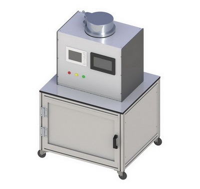
ID Eurosensors paper : 1111-extended version in Sensors and Actuators A 186,198-202,2012. 2 *Corresponding author. Tel.:+41.21.693.77.58; fax: +41.21.693.38.91.E-mail address: nathalie.serra@epfl.ch Piezoresistive effect in epoxy-graphite composites N. Serra *, T. Maeder, P. Ryser Laboratoire de Production Microtechnique,Ecole Polytechnique Federale de Lausanne, Station 17, CH-1015 Lausanne, Switzerland. Original version: http://hdl.handle.net/10.1016/j.sna.2012.04.025 Abstract In this work, we investigate the piezoresistive response of epoxy-graphite composites. A resistive thick-filmWheatstone bridge is deposited by screen-printing onto a beam, a weight is then applied on the tip of the beam andthe resulting electrical signal response is recorded, allowing the calculation of the gauge factor. The characterizationwas made at room temperature, 65℃ and 100°C for different matrixes (epoxies with different glass transitiontemperatures, Tg), substrates (alumina and aluminum) and particles sizes (4 um and 15 um). The creep of the signalin time and temperature was also observed. The present work shows also the tremendous effect of Tg onpiezoresistive behavior: the high Tg epoxy demonstrating better stability in time and temperature than the other one. Keywords: piezoresistivity; epoxy-graphite composite; creep 1. Introduction Percolative materials find increasing use in industrial applications. For instance, thick-film resistors,which essentially consist of conductive oxide nanopowder in an insulating glassy matrix forming a pasteand can be printed on various substrates [1], are used in electronic circuits and may be applied to sensorsfor mechanical and chemical quantities and temperature. Although these materials are of great interest forintegrating sensing functions in high-reliability ceramic [2,3] and metal [4] devices, variants having lowerprocessing temperatures compatible with organic substrates such as printed circuit boards (PCBs) are alsosought for a wider range of applications [5,6]. From this perspective, the use of polymer/graphitecomposites featuring good processability and low-cost materials is very promising. Several properties ofthe material used, such as mechanical or electrical (depending on the type of sensor) must be thereforeconsidered. Nomenclature Tg glass transition temperature GF, GF, GFT gauge factor, longitudinal (GFL) and transverse (GFr) CTE coefficient of thermal expansion In a previous study [7], we studied the conductivity properties of epoxy-graphite composites, regardingparticle size and Tg effects, finally leading to the manufacture of micro-heaters based on these pastes. Tocontinue the characterization of our pastes, we examined the piezoresistive behavior, which is of highinterest for mechanical sensors, expanding on the preliminary version of this work [8]. Piezoresistivityhas already been studied for ceramic [9,10] and polymer [6] thick-films resistors. However it has alsobeen demonstrated that the effects depends strongly on the conductive properties of the filler [9]. As littlework has been done concerning standard graphite (i.e. with an ellipsoidal shape), most of the literaturedealing with graphite fibers or expanded graphite [11,12], we endeavored in this study to investigate thepiezoresistive response of thick-film epoxy-graphite composite. The characterization was completed bythe study of the creep of our beams in temperature. 2. Experimental Test beams were produced using the screen-printing process. Different resistive pastes are depositedon the substrate, in a Wheatstone bridge configuration. For testing, a weight is then applied on the tip ofthe beam and the resulting electrical signal response is recorded, leading, after calculation, to the gaugefactor (longitudinal and transverse). The particle size effect was investigated. Two kinds of graphite weretested as filler: KS4 and KS15. Both variants have an ellipsoidal shape and come from Timcal,Switzerland; KS4 (resp. KS15) meaning that 95% of the particles have a large axis smaller than 4 um(resp. 15 um). Two epoxies were also tested as matrix for the composites; they were chosen with differentTe values, in order to see the impact in creep stability. Table 1 sums up the characteristics of theseepoxies. Pastes were made in each case for different volume fractions of filler: 10%, 12%, 15% and 20%in order to change the conductivity of the composite and observe the corresponding change in thepiezoresistive response. Measurements were made at room temperature, 65℃ and 100℃ for bothmatrixes. By increasing the temperature, we know that thermal expansion of the composite will conflictwith that of the substrate, even more drastically above Tg. Therefore, we decided to produce beams usingtwo kinds of substrates with different CTEs: alumina and aluminum (cf. Table 2). Thermalcharacterization of these materials was performed using an optical dilatometer Misura ODLT 1200-30,from Expert System Solutions. The gauge factor is defined as: where (AR/R) is the relative change in resistance and e the strain with e=Al/l GFL is the case where the current flows along the length of the beam (i.e. the current is parallel to theapplied strain) and GFr where the current flows along the width of the beam (i.e. current perpendicular tothe applied strain). Both factors were determined in our experiments. However only the GFL are discussedhere, the effect being the same for GF but the relative error is higher due to a lower response. Finally, thecreep of the signal vs. time was observed at different temperatures using the same beams. Measurementswere made at25℃, 40°C, 50°C, 60°℃,70°C,80°C and90°C for onecompletecycle(unloaded/loaded/unloaded). Table 1. Main properties of epoxy resins (supplier data) Name Supplier Tg(C) Curing Schedule Epotek 377 PolyScience AG ~90 2h@150℃ Martens Plus Swiss Composite ≈ 200 24h@100C+ 15h@230°℃ Table 2. Main properties of alumina and aluminum substrates (supplier data) Type Alumina Aluminum Supplier Kyocera, Japan Metallica, Switzerland Reference A-476 (96% pure alumina) AW-6082,rolled Thickness [mm] 0.635 0.8 Strain at resistor 0.027 0.054 Young’s Modulus [GPa] 315 69 CTEtheoretical [10/℃] 7.2 23.4 Insulator Same epoxy as resistor +silica powder Conductors / resistor Thick-film Au ink, ESL 8837, Conductive epoxy-Ag adhesive, terminations fired 850°C 10 min Epotecny E212, 5 min at 150°℃ 3. Results 3.1. Substrate characterization Both substrates were characterized using an optical dilatometer. Measurements were done from 25℃to 140°℃ at 10°C/min. Fig 1.a presents the results that were obtained for the thermal expansion. Asexpected, aluminum exhibits a higher thermal expansion than alumina. Although not perfect, aluminumwill ergo restrain less the epoxy in its expansion (see Fig 1.b). One will notice the particular shape of theepoxy thermal expansion curve. A shrinkage can be observed around 100℃. This can be explained byresidual stress inside the matrix in the Tg range, probably coming from the curing: when the epoxyreaches Tg, it becomes plastic and relaxes [13]. Fig 1. Comparison of the thermal expansion of alumina vs. aluminum substrates (a), and aluminumvs. pure Epotek 377 (b) These curves allow the calculation of the coefficient of thermal expansion (CTE), which correspondsto the slope. In the previously defined temperature range, we experimentally found that alumina has aCTE of 6.9 x 10 /℃ and aluminum 25.8×10/C. These values are in agreement with the suppliers’data (see Table 2). 3.2. Piezoresistive behavior A first series of experiments was made on alumina beams to determine the particle size effect onpiezoresistivity. Fig 2a reports the results of the GFL at room temperature vs. volume fraction for KS4 andKS15, the matrix being the epoxy Epotek 377. A higher resistivity is linked to a higher gauge factor [9].At the same volume fraction, smaller particles should create more tunnel junctions, hence smallerresistivity and gauge factor. This is not the case here: the results show that with the smaller particles, thegauge factor is somewhat higher. For a better understanding of the phenomenon, Fig 2.b presents theresults of piezoresistivity vs. resistivity. Indeed, theoretically, we expect the piezoresistivity to increaselinearly with the logarithm of the resistivity; we therefore replot these results as a function of theresistivity on a logarithmic scale. This is verified for both series, KS4 and KS15, in the lower resistivityrange. In this representation of the piezoresistivity as a function of the resistivity, we would expect thetwo fillers to display identical values of the gauge factor, with the smaller filler eventually transitioning toa constant value at lower resistivity values than KS15. Here, although the values are indeed similar, weobserve the opposite behavior. This can be explained by several aspects. First, both fillers are very closein size. Moreover, the theory mainly applies for spherical particles, which is not our case here: the aspectratio of these particles was determined to be 2.6 for KS4 and 3.7 for KS15 [14]. Higher aspect ratios aresupposed to lead to smaller gauge factors, which is what is observed experimentally here. In addition,there are strong indications that percolation in graphite is strongly influenced by debris that are muchsmaller than the primary particles [14], which also may explain the small observed differences betweenboth fillers. Fig.3 presents the results on aluminum substrate. The tendency is the same as on alumina substrate.As piezoresistivity depends strongly on the filler this is quite understandable. We can also notice that theGFL values are slightly higher. Fig 2. Effect of particle size on the GFL vs. graphite volumic concentration (a) and vs. resistivity (b)(substrate: alumina, matrix: Epotek 377, particles: KS4 and KS15) Fig 3. Effect of particle size on the GFL vs. graphite volumic concentration (a) and vs. resistivity (b)(substrate: aluminum, matrix: Epotek 377, particles: KS4 and KS15) A second series of experiments was performed in order to see the impact of matrix thermo-mechanicalstability on the samples. The gauge factor was calculated at room temperature, 65°℃ and 100C. Thecorresponding results are reported in Fig 4. When the temperature is increased and reaches the range ofTg, several effects are in competition: increased thermal expansion of the epoxy in the z direction,compressive stress of the resistor in the xy plane, and decreased matrix stiffness. Due to high differencesin the Young's Modulus between matrix and graphite, most of the mechanical strain is taken up by thematrix, this strain amplification leading to an increase of the gauge factor values [15]. With the high Tgepoxy, this effect is shifted: strains and matrix relaxation effects are lower, leading to an improvedstability. In parallel to that, GF values were compared for samples using Epotek 377 as a matrix onalumina and aluminum. Measurements were not possible at 100°C for aluminum substrate for instabilityreasons, only the results for room temperature and 65°℃ are reported in Fig 5. We can see that the valueschange drastically on aluminum with temperature. Indeed, as the CTE of aluminum is higher than that ofalumina, the strain mismatch with the graphite-epoxy composite is lower, altering the effects describedabove. Fig 4. Longitudinal gauge factor at RT, 65°C and 100°C vs. graphite (KS4) volumic concentrationfor Epotek 377 (a) and Martens Plus (b) on alumina substrate Fig 5. Longitudinal gauge factor at RT and 65°C vs. graphite (KS4) volumic concentration forEpotek 377 on alumina and aluminum substrates 3.3. Study of the piezoresistivity creep Using the same beam, the creep of the signal in time was observed for one complete cycle:unloaded/loaded/unloaded. Fig 6 presents the curves obtained at 12% vol. graphite KS15 for the twoepoxies at 25℃, 50°℃ and 80°℃, on alumina substrate. When the temperature is raised close to the Te ofthe Epotek 377, the material is disturbed due to higher thermal expansion of the matrix and relaxationeffects, leading to strong instabilities (drifts) of the signal and higher GFL values. Another possibilitymight be a low adhesion between matrix and filler, leading to instabilities. Indeed, graphite is non polarand shows poor chemical affinity with the epoxy and tends therefore to agglomerate [16]. This is one ofthe reasons for functionalizing graphite fibers for mechanical applications, for instance through oxidation,the creation of-OH groups on the graphite surface enhancing bonds with the polar groups of the epoxy[18-20]. On the contrary, carbon black presents several impurities, such as oxygen or sulphur [17],leading to a better dispersion inside the matrix. The corresponding piezoresistive response exhibitstherefore a better stability in time. This is the reason why this filler is widely used when makingpiezoresistive sensor [6, 21, 22]. On the other hand, we can observe that the Martens Plus, while notperfect, expectedly exhibits a better stability regarding creep. The same experiment was performed on aluminum with 12% vol. of graphite in Epotek 377 as amatrix. The results are reported in Fig 7. At room temperature, the GFL values change dramatically on thealuminum substrate, due to instability during the measurement and the aluminum ductility. When theweight is put on the beam tip, a higher strain is exerted than on alumina. If we now consider the effect oftemperature, the tendency is the same as on alumina substrate: we can see that the signal observed onaluminum shows strong instabilities when the temperature is raised close to the Tg range. The effect iseven increased, due to the fact that the thermal expansion of the epoxy on aluminum is higher. 4. Conclusion The piezoresistive response of thick-film epoxy-graphite composite materials was studied on twodifferent substrates: alumina and aluminum. We demonstrate that particle size has a somewhat moreimportant effect than in resistivity measurements, due to the tunneling effect. We also once morehighlighted the role of Te on mechanical stability, which sets the application temperature ceiling, as thematerial will dilate and rapidly relax around this temperature. Both of these effects were verified onaluminum substrate and were even amplified due to aluminum thermal expansion. Finally, creep wasobserved at different temperatures. We can see that even at room temperature, the higher Te epoxy,though not perfect, presents better stability in time. These results are therefore promising for applicationto low-cost mechanical sensors. Additionally, functionalizing the graphite surface to achieve bettercohesion with the epoxy may further improve stability. Acknowledgements The authors would like to thank Timcal for the graphite powders and Mathias Garcin formanufacturing the samples. This work was partly financed by the Swiss CTI promotion agency. Fig 6. Signal vs. time for 12% vol of graphite in Epotek 377 and Martens Plus at 25°C (a), 50°C (b)and 80°C (c) t[min] t [min] Fig 7. Signal vs. time for 12% vol.of graphite in Epotek 377 on alumina and aluminum substrate at25℃ (a),50°℃(b) and 80°℃ (C) References [1]N1.M. White, J.D. Tuner. Thick-film sensors: past, present and future. Measurement Science and Technology 1997;8:1-20. [2]S. Vionnet, T. Maeder, P. Ryser. Firing, quenching and annealing studies on thick-film resistors. Journal of the EuropeanCeramic Society 2004;24:1889-1892. ( [3] S : . Vionnet-Menot, T. Ma e der, C. Grimaldi, P. Rys e r. Properties and stability ofthick-film resistors with low processingtemperatures - effect ofcomposition and processing parameters. Jou r nal of Microelectronics and Electronic Packaging 2006;3:37-43. ) ( [41] ] T.M a eder, C. Jacq, P. Ryser. Low - firing thick-film piezoresistive sensors for medical instruments. Sensors and Actuators A 2011;172:228-232. ) ( 5] 1 G . Harsanyi, E .Hahn, Thick-film pressure sensors, Mechatronics 1993;3:167-171. ) ( A . Dziedzic, A. M a giera, R.Winsiewski. Hydr o static high pressure studies of polymer thick-film resistors. MicroelectronicsReliability 1998;38:1893-1898. ) ( [7] ] N . Serra, T. M aeder, P . Lemaire, P. R y ser. Formulation of composite resistive pastes for fabrication of microheaters. Sensorsand Actuators A: Physical 2010;162:367-372. ) ( N. Serra,T. Maeder, P. Ryser, Piezoresistive effect in epoxy-graphite composites. Procedia Eng i neering 2011;25:235-238. ) ( C . Ca n ali, D. Malavasi, B . Morten, M. Pr u denziati, A. Ta r oni. Pi e zoresistive effects in thick-film resistors. Journal ofApplied Physics 1980;51:3282-3288. ) ( [10] S. Vionnet Menot. Low f i ring temperature thick-film piezoresistive composites-Properties and conduction mechanism. T h esis n °3290,2 0 05,Ec o le Po l ytechnique Fe d erale de Lausanne. ) ( [11] F. Carmona, R. Canet, P . Delhaes. Piezoresistivity of heterogeneous solids.Journal of Applied Physics 1987;61:2550-2557. ) [12] S. Qu, S-C Wong. Piezoresistive behavior of polymer reinforced by expanded graphite. Composites Science and Technology2007:67:231-237. [13] S. Tognana, W. Salgueiro, A. Samoza, J.A. Pomarico, H.F. Ranea-Sandoval. Influence of the filler content on the thermalexpansion behavior of an epoxy matrix particulate compsite. Materials Science and Engineering B 2009;157:26-31 [14] G. Ambrosetti. On the insulator-conductor transition in polymer nanocomposite, Thesis n°4612 EPFL, 2010 [15] C. Grimaldi, P. Ryser, S. Strassler. Gauge factor enhancement driven by heterogeneity in thick-film resistor. Journal of AppliedPhysics 2001;90:322-327 [16] C-N. Chen, Y-L. Chen, W.J. Tseng. Surfactant-assited de-agglomeration of graphite nanoparticles by wet ball mixing. Journalof Materials Processing Technology 2007;190:61-64 [17] W. Zu, D.E. Miser, W.G. Chan, M.R. Hajaligol. HRTM investigation of some commercially available furnace carbon blacks.Carbon 2004:42:1841-1845 [18] S. Yumitori, Y. Nakanishi.Effect of anodic oxidation of coal tar pitch-based carbon fiber on adhesion in epoxy matrix: Part 1. Comparison between H2SO4 and NaOH solutions. Composites Part A 1996;27A;1051-1058 [19] S. Yumitori, Y. Nakanishi. Effect of anodic oxidation of coal tar pitch-based carbon fiber on adhesion in epoxy matrix: Part 1.Comparative study of three alkaline solutions. Composites Part A 1996;27A;1059-1066 ( [20] S . Ganguli, A . K. Roy, D . P. Anderson. Im p roved thermal conductivity for chemically functionalized exfoliated g raphite/epoxy composites. Carbon 2008;46:806-817 ) ( [21] A. Dziedzic, A. K olek. 1/f n oise i n polymer thick-film resistors. Journal of Physics D: Applied Physics 1998;31:2091-2097 ) ( [22] A. D ziedzic. Carbon/polyesterimide thick-film resistive composites-experimental characterization and the o retical analysis ofphysicochemical, el e ctrical and stability p r operties. M i croelectronics reliability 2007;47:354-362 ) Biographies Nathalie Serra graduated in September 2007 (master degree in chemistry) at the“Ecole NationaleSuperieure de Chimie de Lille”which is part of the French“Grandes Ecoles”network, and is pursuing aPhD in resistive nanocomposites at the EPFL. Thomas Maeder pursued with a PhD in piezoelectric thin films, and a post-doc at IBM Riischlikon insingle-crystal conductive oxides, after graduating from the Ecole Polytechnique Federale de Lausanne(EPFL) in materials science. He now heads the thick-film technology group at the EPFL, where currentareas of interest are thick-film and LTCC technology for advanced sensor and packaging applications,and sensor networking. Peter Ryser received a Master degree in Physics (University Neuchatel 1979), a PhD in appliedPhysics (University Geneva 1985) and a Masters Degree in Corporate Management (Lucerne 1993). Hisprofessional background includes several R&D activities. From 1990-1998 he was the head of research atSiemens Building Technologies. Since 1999 Peter Ryser is Professor at the Swiss Federal Institute ofTechnology EPFL in Lausanne and act as a director for the micro engineering section. 本文介绍了对石墨环氧复合材料压敏电阻效应的研究工作。将一个厚膜电阻形式的惠斯登电桥采用丝网印方式沉积在横梁试样上,并在横梁试样端头加载一重量,采用光学膨胀仪同时记录下相应的变形位移信号,并计算出量规因数。整个测试过程在室温、65℃和100℃三个温度下进行,并对不同的基材(具有不同玻璃化转变温度的树脂基)、不同衬底材料(氧化铝和铝)和不同大小颗粒(4um和15um)进行测试,同时观测信号随时间和温度的渐变过程。试验结果表明玻璃化转变温度对压电电阻效应有巨大的影响,树脂高的玻璃化转变温度无论在时间还是温度方面都对压电电阻效应的稳定器起到最主要的作用。
关闭-
1/9

-
2/9
还剩7页未读,是否继续阅读?
继续免费阅读全文产品配置单
上海依阳实业有限公司为您提供《复合材料中热膨胀系数,变形,位移,膨胀系数检测方案(热膨胀仪)》,该方案主要用于其它中热膨胀系数,变形,位移,膨胀系数检测,参考标准《暂无》,《复合材料中热膨胀系数,变形,位移,膨胀系数检测方案(热膨胀仪)》用到的仪器有光学投影法高温热膨胀仪。
我要纠错
推荐专场
相关方案
 咨询
咨询