

方案详情文
智能文字提取功能测试中
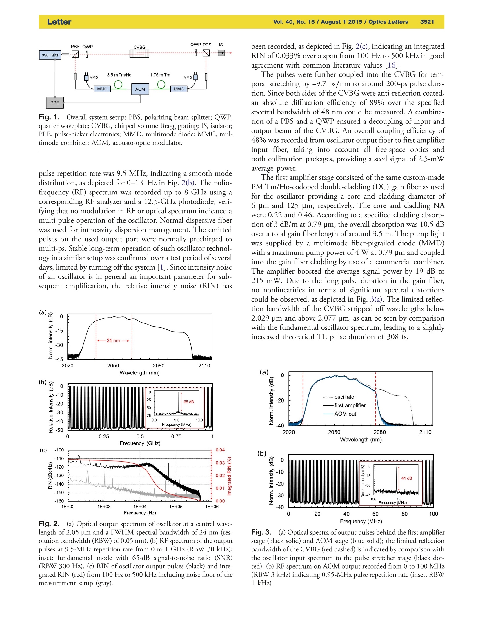
3520LetterVol. 40, No. 15 / August 1 2015 / Optics LettersOptics Letters 0146-9592/15/153520-04$15/O$15.00 C 2015 Optical Society of America Compact polarization-maintaining 2.05-um fiberlaser at 1-MHz and 1-MW peak power HEINAR HOOGLAND1,2* AND RONALD HoLZWARTH1,3 'Menlo Systems GmbH, Am Klopferspitz 19a, 82152 Martinsried, Germany Department of Physics, University of Erlangen-Nuremberg, Staudtstrasse 1, 91058 Erlangen, Germany Max-Planck-Institute of Quantum Optics, Hans-Kopfermann-Strasse 1, 85748 Garching, Germany *Corresponding author: h.hoogland@menlosystems.com Received 11 May 2015; revised 8 July 2015; accepted 8 July 2015; posted 9 July 2015 (Doc.ID 240630); published 23 July 2015 We report on a compact all-polarization-maintaining2.05-pm chirped pulse fiber amplifier system emittingpulses at up to 1-MW peak power level at 371-fs pulseduration. The seed pulse repetition rate provided by aninhouse-built oscillator is reduced to around 1 MHz usinga pulse picker. In combination with a two stage fiber am-plifier, output pulse energies up to 570 nJ are obtainedwithout the need of a high-power large-mode area ampli-fier. Both temporal stretching and compression of thechirped pulse amplifier design are achieved using asingle chirped volume Bragg grating. @ 2015 OpticalSociety of America OCIS codes: (060.2320) Fiber optics amplifiers and oscillators;(140.3280) Laser amplifiers; (320.5520) Pulse compression. http://dx.doi.org/10.1364/OL.40.003520 The field of ultrashort pulsed 2-um lasers is rapidly evolving interms of reliability and performance due to an increased interestin such light sources for various applications. Especially due tothe characteristic eye-safe operation regime at reasonable powerlevels, ultrashort pulsed sources at 2 um are favored for airborneapplications in the field of security as well as defense.Furthermore, fiber-based frontend lasers emitting ultrashortpulses at 2 um provide stable seeding of high pulse energyHo:YAG [1] and Ho:YLF [2,3] based solid state amplifiersystems or can be used for mid-IR light generation bydifference-frequency generation (DFG) [4]. A direct applica-tion of ultrashort 2-um sources is given in the field ofdielectric laser acceleration of nonrelativistic and relativisticelectrons due to the scaling of its dephasing length with inputlaser beam wavelength [5,6]. Pulses at around 1.9-2 um can begenerated using modelocked Thulium (Tm)-based oscillatorcavities [7-9]. To further push the oscillator central wavelengthbeyond 2 um, nonlinear shifting of a Tm-based oscillator out-put [10-12] or gain region shifting by reabsorption usingdouble-clad (DC) pumping of lengthened Tm doped fibers[13] has proven successful. Furthermore, Holmium (Ho) as codopant [14,15] or single dopant [16] can be used to furtherextend the gain region of the active fiber. For amplification at2 pm, the chirped-pulse amplification (CPA) scheme has beendemonstrated in several 2-um laser setups, e.g., using a combi-nation of fiber stretcher and free-space compression [17,18] ora single chirped volume Bragg grating (CVBG) [12]. Using acombination of a CVBG stretcher and Treacy compressor in alarge-mode area (LMA) based CPA system, running at repeti-tion rates down to 100 kHz, peak powers up to 3 MW havebeen demonstrated [19]. Using a Martinez stretcher and Treacycompressor assembly in combination with a water-cooledlarge-pitch rod-type Tm-doped photonic crystal fiber (PCF),pulses at 100 kHz at a peak power of 200 MW were recentlydemonstrated [20]. However, current fiber-based amplifier systems often sufferthe lack of suitable all-polarization-maintaining (PM) compactdesigns provided over the entire optical system, giving rise totemperature related and optomechanical instabilities. This es-pecially applies to direct seeding by oscillators at 2 pm thatoften rely on non-PM structures. To gain high peak powersof beyond 100 kW, CPA systems mostly rely on complexstretcher/compressor setups for temporal chirp managementon the one side and LMA fiber amplifiers that could cause mul-timode interference on the other side [17,19]. In this Letter, we present a compact all-PM CPA system, di-rectly oscillator-seeded at 2.05-um central wavelength, allowingfor ultrashort output pulses at 570 nJ with up to around1.1-MW peak power at 0.95-MHz repetition rate without theneed of typical LMA fiber amplifiers or complex stretcher/compressor setups. A repetition rate of 0.95 MHz was chosenas tradeoff between high peak powers at reasonable averageoutput powers suitable for follow-up applications. The overallschematic setup is shown in Fig. 1. An all-PM fiber oscillator, based on nonlinear optical loopmirror (NOLM) modelocking in “Fig. 9” design [21], as varia-tion of the common “Fig. 8”principle [22], generated seedpulses at 2.05 um and 5.2 mW average power with afull width at half-maximum (FHWM) spectral bandwidth of24 nm, as depicted in Fig. 2(a), supporting a theoretical trngans-form-limited (TL) pulse duration of 241 fs. The fundamental Fig. 1. Overall system setup: PBS, polarizing beam splitter; QWP,quarter waveplate; CVBG, chirped volume Bragg grating; IS, isolator;PPE, pulse-picker electronics; MMD, multimode diode;MMC, mul-timode combiner; AOM, acousto-optic modulator. pulse repetition rate was 9.5 MHz, indicating a smooth modedistribution, as depicted for 0-1 GHz in Fig. 2(b). The radio-frequency (RF) spectrum was recorded up to 8 GHz using acorresponding RF analyzer and a 12.5-GHz photodiode, veri-fying that no modulation in RF or optical spectrum indicated amulti-pulse operation of the oscillator. Normal dispersive fiberwas used for intracavity dispersion management. The emittedpulses on the used output port were normally prechirped tomulti-ps. Stable long-term operation of such oscillator technol-ogy in a similar setup was confirmed over a test period of severaldays, limited by turning off the system [1]. Since intensity noiseof an oscillator is in general an important parameter for sub-sequent amplification, the relative intensity noise (RIN) has Fig. 2..(a) Optical output spectrum of oscillator at a central wave-length of 2.05 pm and a FWHM spectral bandwidth of 24 nm (res-olution bandwidth (RBW) of 0.05 nm). (b) RF spectrum of the outputpulses at 9.5-MHz repetition rate from 0 to 1 GHz (RBW 30 kHz);inset: fundamental mode with 65-dB signal-to-noise ratio (SNR)(RBW 300 Hz). (c) RIN of oscillator output pulses (black) and inte-grated RIN (red) from 100 Hz to 500 kHz including noise floor of themeasurement setup (gray). been recorded, as depicted in Fig. 2(c), indicating an integratedRIN of 0.033% over a span from 100 Hz to 500 kHz in goodagreement with common literature values [16]. The pulses were further coupled into the CVBG for tem-poral stretching by -9.7 ps/nm to around 200-ps pulse dura-tion.Since both sides of the CVBG were anti-reflection coated,an absolute diffraction efficiency of 89% over the specifiedspectral bandwidth of 48 nm could be measured. A combina-tion of a PBS and a QWP ensured a decoupling of input andoutput beam of the CVBG. An overall coupling efficiency of48% was recorded from oscillator output fiber to first amplifierinput fiber, taking into account all free-space optics andboth collimation packages, providing a seed signal of 2.5-mWaverage power. The first amplifier stage consisted of the same custom-madePM Tm/Ho-codoped double-cladding (DC) gain fiber as usedfor the oscillator providing a core and cladding diameter of6 um and 125 um, respectively. The core and cladding NAwere 0.22 and 0.46. According to a specified cladding absorp-tion of 3 dB/m at 0.79 um, the overall absorption was 10.5 dBover a total gain fiber length of around 3.5 m. The pump lightwas supplied by a multimode fiber-pigtailed diode (MMD)with a maximum pump power of 4 W at 0.79 um and coupledinto the gain fiber cladding by use of a commercial combiner.The amplifier boosted the average signal power by 19 dB to215 mW. Due to the long pulse duration in the gain fiber,no nonlinearities in terms of significant spectral distortionscould be observed, as depicted in Fig. 3(a). The limited reflec-tion bandwidth of the CVBG stripped off wavelengths below2.029 um and above 2.077 um, as can be seen by comparisonwith the fundamental oscillator spectrum, leading to a slightlyincreased theoretical TL pulse duration of 308 fs. Fig.3.l.(a) Optical spectra of output pulses behind the first amplifierstage (black solid) and AOM stage (blue solid); the limited reflectionbandwidth of the CVBG (red dashed) is indicated by comparison withthe oscillator input spectrum to the pulse stretcher stage (black dot-ted). (b) RF spectrum on AOM output recorded from 0 to 100 MHz(RBW 3 kHz) indicating 0.95-MHz pulse repetition rate (inset, RBW1 kHz). The output of the first amplifier was coupled into a com-mercial inline acousto-optic modulator (AOM) used as pulsepicker. As trigger signal, an additional monitor port of theoscillator supplied the fundamental 105-ns spaced pulse trainsignal. Inhouse-built pulse-picking electronics provided a RFsignal of around 0.-us width to the AOM, ensuring propersingle-pulse selection. The overall optical AOM stage through-put including all insertion losses at 1/10 pulse selection ratiowas measured to be 2.1%. The corresponding optical outputspectrum is depicted in Fig. 3(a). The pulse-picked repetitionrate at 0.95 MHz is shown in Fig. 3(b), indicating an SNRof 41 dB. An additional amplifier stage was used to compensate1er for thelosses in average power introduced by the AOM stage, thusscaling the pulse energy toward higher levels due to the reducedrepetition rate. First experiments were carried out relying onthe same Tm/Ho gain fiber as used for the first amplifier.Although the pulses were significantly temporally stretched,the increased pulse energy at reduced repetition rate led to highpeak intensities inside the gain fiber due to the small core size ofthe Tm/Ho fiber, leading to the onset of spectral distortions bynonlinearities at relatively low pulse energies. Therefore, thesecond amplifier gain fiber was replaced with a Tm-dopedPM-DC fiber (Nufern) with an increased core diameter of10 um (NA 0.15), corresponding to an around 2.8 times in-creased effective area. The pump light was delivered by a secondMMD supplying up to 13-W optical power at 0.79 um. A totalgain fiber length of 1.75 m has been chosen as a tradeoffbetween pump light absorption and introduced anomalousdispersion, corresponding to a calculated pump light absorp-tion of 8.2 dB at 0.79 um. The amplifier output light was di-rectly coupled into the opposite direction of the CVBG forpulse compression, similar to the stretcher setup [23], thusintroducing a dispersion of +9.7 ps/nm to the output pulses.To protect the laser system from back-reflection, a free-spaceisolator was installed on the compression stage output. An over-all coupling efficiency of 71% from amplifier output to isolatoroutput was recorded at low average signal power. To investigate amplification behavior, the second amplifierhas been preliminary tested for both forward and backwardpumping, as depicted in Fig. 4(a). For this measurement,the average output power was recorded on the isolator output,thus including all losses introduced by the compressor stage.Above 4-W pump power, the backward pumping schemeshowed a significantly increased gain compared to forwardpumping. At 10.5-W pump power, the output power couldbe increased by a factor of 1.4 using backward pumping.Furthermore, it could be seen that for both pump directions,the gain significantly decreased for pump powers above 8 W.Since the output power was recorded behind the compressionstage, this drop in gain could be explained by the filtering effectof the CVBG, stripping off all spectral components outside thegrating reflection bandwidth that rose, mainly by an increasedamplified spontaneous emission (ASE) located at 1.9 to 2 um,covering up to around 23% of the average output power di-rectly behind the second amplifier at 10.5-W pump power.Thus, the compressor acted as a spectral cleaner, removing en-ergy in unwanted spectral regions. To ensure stable operation Fig.4.(a) Average output power to launched pump power for back-ward (black) and forward (red) pumping. (b) Optical output spectrumbehind compressor stage (red marked: CVBG bandwidth) indicatingthe onset of nonlinearities by spectral modulation. and to prevent from optical damage by an onset of parasiticlasing or Q-switching, no higher pump powers were applied.Due to its overall increased performance, backward pumpingwas chosen for the final setup, yielding 570-nJ pulses at a totalgain of 21 dB. However, at these pulse energies, nonlinearitiesled to spectral modulation on the compressor-stage output,as depicted in Fig. 4(b). The retrieved spectral FWHM band-width of 13 nm corresponded to a theoretical TL pulse dura-tion of 294 fs. A polarization extinction ratio (PER) of 22.1 dBwas recorded behind the compressor stage. The highest peak power of around 1.1 MW was recordedat 570-nJ pulse energy and 371-fs pulse duration. The pulseduration corresponded to a factor of 1.26 compared to thetheoretical TL duration of 294 fs as calculated from the opticaloutput spectrum of the compressor stage. The deviation is aresult of lacking fine adjustment of group velocity dispersion, Fig. 5.(a) FROG retrieved temporal pulse shape at 354 nJ (blackdashed) and 570 nJ (black solid) at 374- and 371-fs pulse duration;phase profile of output pulse at 570 nJ (red solid). (b) Pulse durationwith respect to pulse energy (black) including recorded FROG error(red); minimum pulse duration of 366 fs was measured at 443-nJ pulseenergy; 570 nJ at 371-fs pulse duration corresponded to around1.1-MW peak power contained within the pulse main peak. TOD, and nonlinearities. However, the amplification processcorresponds to a quite linear behavior, since significant varia-tion of the output pulse energy only slightly varied the temporalstructure of the output pulses. In conclusion, we demonstrated a compact all-PM CPAsystem, directly seeded by an oscillator running at 2.05 pm,incorporating an AOM-based pulse picker to achieve pulseenergies of 570 nJ at an ultrashort pulse duration of around371 fs, corresponding to above 1-MW peak power at 0.95-MHz repetition rate. A two-stage fiber amplifier was used toboost the pulse energy, supporting strict single-mode operationwithout the need of an additional high-power LMA gain fiber-based amplifier stage. A single CVBG was used for both stretch-ing and compression of the pulses to avoid nonlinearities in thefiber amplifiers, rendering complex stretcher/compressor setupsobsolete. Fine adjustment of dispersion was achieved bysuitable choice of fiber lengths. Upcoming work will focuson improving the dispersion management to step toward theTL pulse duration. Furthermore, additional amplifier designswill be studied to enable 可 pulse energy level. Funding.Bundesministerium fur Bildung und Forschung(BMBF) MIRANDUS (E! 6698) Acknowledgment. We gratefully thank our electronicsdepartment for its efforts in this work. REFERENCES 1. P. Malevich, T. Kanai, H. Hoogland,R. Holzwarth, A. Baltuska, and A.Pugzlys, CLEO 2015-Laser Applications to Photonic Applications,OSA Technical Digest (CD) (Optical Society of America, 2015),paper SM1P.4. 2. M. Hemmer, D. Sanchez, M. Jelinek, V. Smirnov, H. Jelinkova, V.Kubecek, and J. Biegert, Opt. Lett. 40, 451 (2015). 3. K.Murari, H. Cankaya, P. Li, A. Ruehl, I. Hartl, and F. X. Kartner, 6thEPS-QEOD EUROPHOTON Conference Digest (European PhysicalSociety, 2014), paper ThD-T1-O-05. 4. D. Sanchez, M. Hemmer, M. Baudisch, K. Zawilski, P. Schunemann,H. Hoogland, R. Holzwarth, and J. Biegert, Opt. Lett. 39, 6883(2014). 5. J. Breuer, J. McNeur, and P. Hommelhoff, J. Phys. B 47, 234004(2014). 6. J. Breuer, R. Graf, A. Apolonski, and P. Hommelhoff, Phys. Rev. STAccel. Beams 17, 021301 (2014). 7. L. E. Nelson, E. P. Ippen, and H. A. Haus, Appl. Phys. Lett. 67, 19(1995). 8. M. Engelbrecht, F. Haxsen, A. Ruehl, D. Wandt, and D. Kracht,Opt. Lett. 33, 690 (2008). 9. A. Wienke, F. Haxsen, D. Wandt, U. Morgner, J. Neumann, and D.Kracht, Opt. Lett. 37,2466 (2012). 10. R. Sims, P. Kadwani, L. Shah, and M. Richardson, Advances inOptical Materials, OSA Technical Digest (CD) (Optical Society ofAmerica, 2011), paper ATuD4. 11. J. Jiang, A. Ruhl, 1. Hartl, and M. E. Fermann, CLEO 2011-LaserApplications to Photonic Applications, OSA Technical Digest (CD)(Optical Society of America, 2011), paper CThBB5. 12. R. A. Sims, P. Kadwani, H. Ebendor-Heideprem, L. Shah, T. M.Monro, and M. Richardson, Appl. Phys. B 111, 299 (2013). 13. C. W. Rudy, K. E. Urbanek, M. J. F. Digonnet, and R. L. Byer,J. Lightwave Technol. 31, 1809 (2013). 14. Q. Wang, J. Geng, Z. Jiang, T. Luo, and S. Jiang, IEEE Photon.Technol. Lett. 23, 682 (2011). 15. H. Hoogland, S. Wittek, W. Hansel, S. Stark, and R. Holzwarth,Opt. Lett. 39, 6735 (2014). 16. P. Li, A. Ruehl, U. Grosse-Wortmann, and I. Hartl, Opt. Lett. 39, 6859(2014). 17. F. Haxsen, D. Wandt, U. Morgner, J. Neumann, and D. Kracht,Opt. Lett. 35, 2991 (2010). 18. P. Wan, L.-M. Yang, and J. Liu, Opt. Express 21, 21374 (2013). 19. R. A. Sims, P. Kadwani, A. Sincore, L. Shah, and M. Richardson,Opt. Lett. 38, 121 (2013). 20. F. Stutzki, C. Gaida,M. Gebhardt, F. Jansen, C. Jauregui, J. Limpert,and A. Tunnermann, Opt. Lett. 40, 9 (2015). 21. H. Hoogland, S. Wittek, W. Hansel, and R. Holzwarth, CLEO, OSATechnical Digest (Optical Society of America, 2014), paper SM10.5.22. I. N. Duling, Opt. Lett. 16, 539 (1991). 23. A. Galvanauskas,A. Heaney, T. Erdogan, and D. Harter, Summariesof Papers Presented at the Conference on Lasers and Electro-Optics(CLEO), Technical Digest (IEEE, 1998), p. 362.
关闭-
1/4
-
2/4
还剩2页未读,是否继续阅读?
继续免费阅读全文产品配置单
广州市固润光电科技有限公司为您提供《激光中激光脉宽检测方案(激光产品)》,该方案主要用于其他中理化性能检测,参考标准《暂无》,《激光中激光脉宽检测方案(激光产品)》用到的仪器有FROGscan+自相关仪+ODL、自相关仪-FR-103。
我要纠错
相关方案
 咨询
咨询