

方案详情文
智能文字提取功能测试中
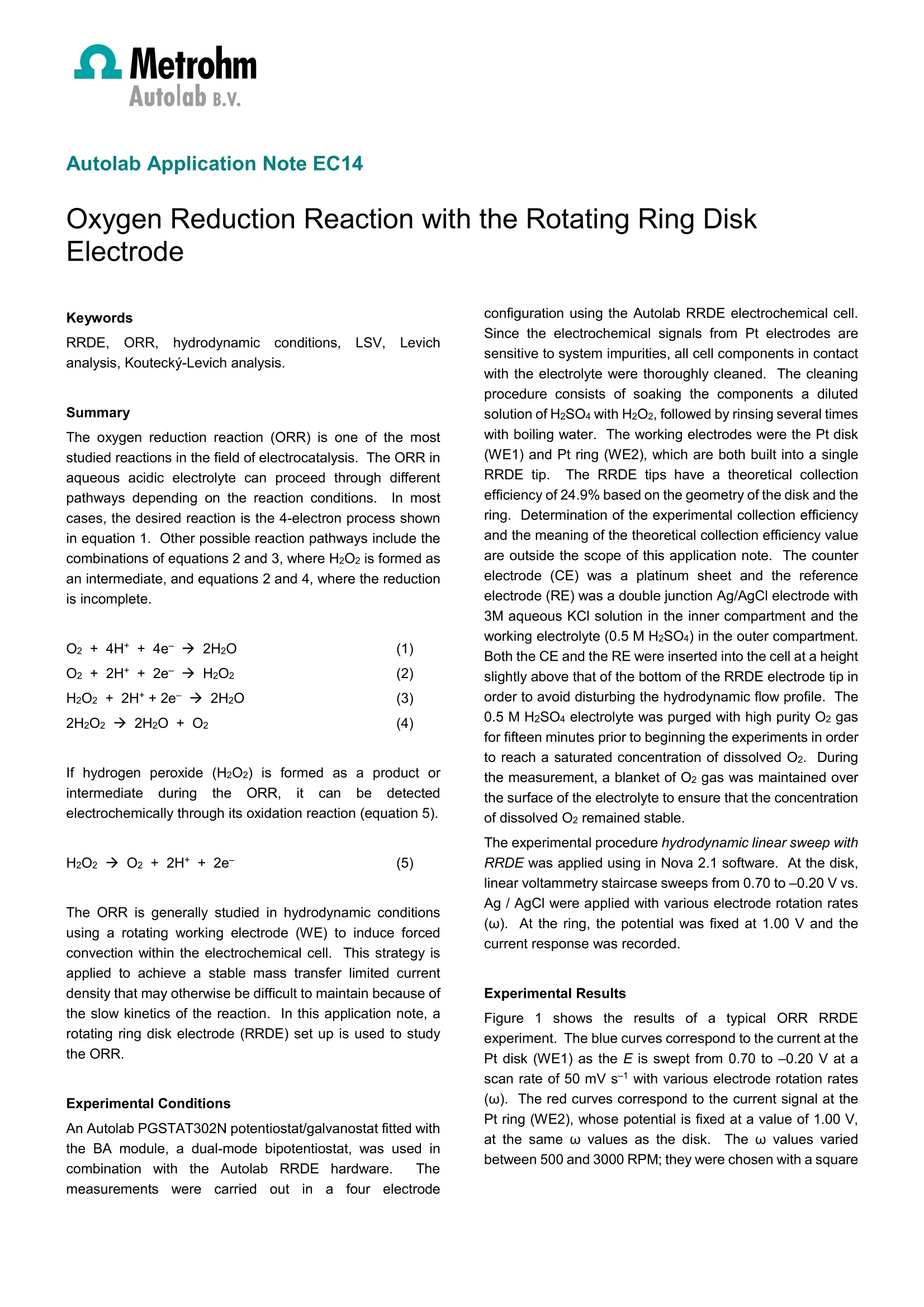
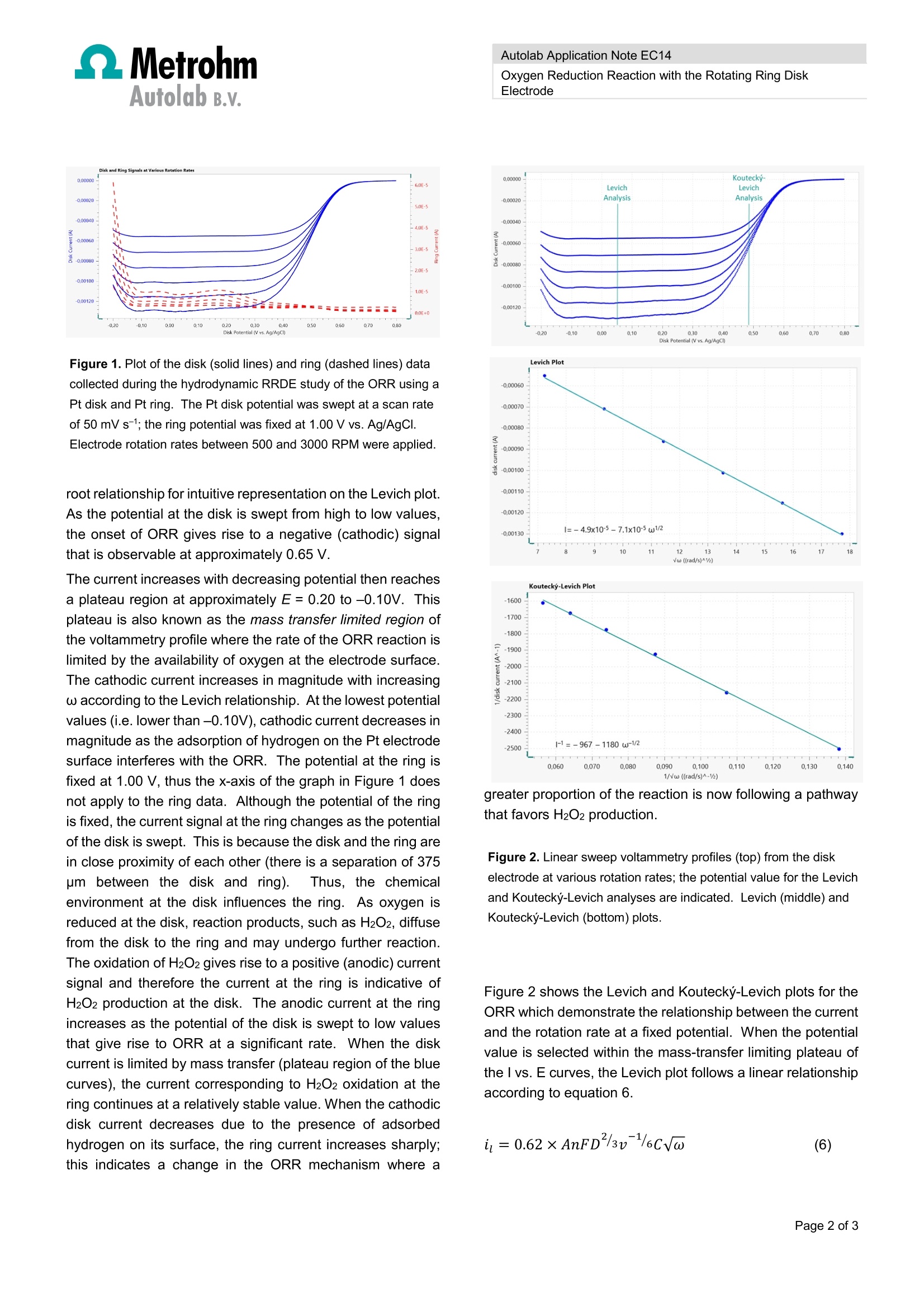
MetrohmAutolab B.v. Autolab Application Note EC14 Autolab Application Note EC14 Oxygen Reduction Reaction with the Rotating Ring DiskElectrode Keywords RRDE, ORR,R,hydrodynamicconditions.,LSV. Levichanalysis, Koutecky-Levich analysis. Summary The oxygen reduction reaction (ORR) is one of the moststudied reactions in the field of electrocatalysis. The ORR inaqueous acidic electrolyte can proceed through differentpathways depending on the reaction conditions..In mostcases, the desired reaction is the 4-electron process shownin equation 1. Other possible reaction pathways include thecombinations of equations 2 and 3, where H2O2 is formed asan intermediate, and equations 2 and 4, where the reductionis incomplete. If hydrogen peroxide (H2O2) is formed as a product orintermediateduringgttthe ORR.R,it cannbbe ddetectedelectrochemically through its oxidation reaction (equation 5). The ORR is generally studied in hydrodynamic conditionsusing a rotating working electrode (WE) to induce forcedconvection within the electrochemical cell. This strategy isapplied to achieve a stable mass transfer limited currentdensity that may otherwise be difficult to maintain because ofthe slow kinetics of the reaction. In this application note, arotating ring disk electrode (RRDE) set up is used to studythe ORR. Experimental Conditions An Autolab PGSTAT302N potentiostat/galvanostat fitted withthe BA module, a dual-mode bipotentiostat, was used incombination with the Autolab RRDEhardware. Themeasurements were(carrieddoutitir afourelectrode configuration using the Autolab RRDE electrochemical cell.Since the electrochemical signals from Pt electrodes aresensitive to system impurities, all cell components in contactwith the electrolyte were thoroughly cleaned. The cleaningprocedure consists of soaking the components a dilutedsolution of H2SO4 with H2O2, followed by rinsing several timeswith boiling water. The working electrodes were the Pt disk(WE1) and Pt ring (WE2), which are both built into a singleRRDE tip.The RRDE tips have a theoretical collectionefficiency of 24.9% based on the geometry of the disk and thering. Determination of the experimental collection efficiencyand the meaning of the theoretical collection efficiency valueare outside the scope of this application note. The counterelectrode (CE) was a platinum sheet and the referenceelectrode (RE) was a double junction Ag/AgCl electrode with3M aqueous KCI solution in the inner compartment and theworking electrolyte (0.5 M H2SO4) in the outer compartment.Both the CE and the RE were inserted into the cell at a heightslightly above that of the bottom of the RRDE electrode tip inorder to avoid disturbing the hydrodynamic flow profile. The0.5 M H2SO4 electrolyte was purged with high purity O2 gasfor fifteen minutes prior to beginning the experiments in orderto reach a saturated concentration of dissolved O2. Duringthe measurement, a blanket of O2 gas was maintained overthe surface of the electrolyte to ensure that the concentrationof dissolved O2 remained stable. The experimental procedure hydrodynamic linear sweep withRRDE was applied using in Nova 2.1 software. At the disk,linear voltammetry staircase sweeps from 0.70 to -0.20V vs.Ag / AgCl were applied with various electrode rotation rates(w). At the ring, the potential was fixed at 1.00 V and thecurrent response was recorded. Experimental Results Figure 1 shows the results of a typical ORR RRDEexperiment. The blue curves correspond to the current at thePt disk (WE1) as the E is swept from 0.70 to -0.20 V at ascan rate of 50 mV s-1 with various electrode rotation rates(w). The red curves correspond to the current signal at thePt ring (WE2), whose potential is fixed at a value of 1.00 V,at the same w values as the disk.The w values variedbetween 500 and 3000 RPM; they were chosen with a square Autolab B.v. Figure 1. Plot of the disk (solid lines) and ring (dashed lines) datacollected during the hydrodynamic RRDE study of the ORR using aPt disk and Pt ring. The Pt disk potential was swept at a scan rateof 50 mV s-; the ring potential was fixed at 1.00 V vs. Ag/AgCI.Electrode rotation rates between 500 and 3000 RPM were applied. root relationship for intuitive representation on the Levich plot.As the potential at the disk is swept from high to low values,the onset of ORR gives rise to a negative (cathodic) signalthat is observable at approximately 0.65 V. The current increases with decreasing potential then reachesa plateau region at approximately E=0.20 to -0.10V. Thisplateau is also known as the mass transfer limited region ofthe voltammetry profile where the rate of the ORR reaction islimited by the availability of oxygen at the electrode surface.The cathodic current increases in magnitude with increasingw according to the Levich relationship. At the lowest potentialvalues (i.e. lower than -0.10V), cathodic current decreases inmagnitude as the adsorption of hydrogen on the Pt electrodesurface interferes with the ORR. The potential at the ring isfixed at 1.00 V, thus the x-axis of the graph in Figure 1 doesnot apply to the ring data. Although the potential of the ringis fixed, the current signal at the ring changes as the potentialof the disk is swept. This is because the disk and the ring arein close proximity of each other (there is a separation of 375pm between the disk and ring). Thus, the chemicalenvironment at the disk influences the ring. As oxygen isreduced at the disk, reaction products, such as H2O2, diffusefrom the disk to the ring and may undergo further reaction.The oxidation of H2O2 gives rise to a positive (anodic) currentsignal and therefore the current at the ring is indicative ofH2O2 production at the disk. The anodic current at the ringincreases as the potential of the disk is swept to low valuesthat give rise to ORR at a significant rate. When the diskcurrent is limited by mass transfer (plateau region of the bluecurves), the current corresponding to H2O2 oxidation at thering continues at a relatively stable value. When the cathodicdisk current decreases due to the presence of adsorbedhydrogen on its surface, the ring current increases sharply;this indicates a change in the ORR mechanism where a Oxygen Reduction Reaction with the Rotating Ring DiskElectrode vw ((rad/s)^1a greater proportion of the reaction is now following a pathwaythat favors H2O2 production. Figure 2. Linear sweep voltammetry profiles (top) from the diskelectrode at various rotation rates; the potential value for the Levichand Koutecky-Levich analyses are indicated. Levich (middle) andKoutecky-Levich (bottom) plots. Figure 2 shows the Levich and Koutecky-Levich plots for theORR which demonstrate the relationship between the currentand the rotation rate at a fixed potential. When the potentialvalue is selected within the mass-transfer limiting plateau ofthe I vs. E curves, the Levich plot follows a linear relationshipaccording to equation 6. Autolab B.v. When the potential is selected from the region where thecurrent is under a mixture of kinetic and mass transfer control,the Koutecky-Levich plot is liner according to equation 7. For both equations 6 and 7, the variables are defined as: A is the geometric area of the disk(cm2) F is Faraday's constant (C mol1) D is the diffusion coefficient of O2 in the electrolyte (cm²s-) v is the kinematic viscosity of the electrolyte (cm²s-1) C is the concentration of O2 in the electrolyte (mol cm)w is the angular frequency of rotation (rad s-1) n is the number of electrons involved in the reaction The Levich and the Koutecky-Levich plots can be fitted usinglinear regression to calculate the slopes and intercepts. Forthe Koutecky-Levich plot, the kinetic current (ik) is calculatedfrom the y-intercept which is equal to 1/ik. According toequation 8, the ik value can be related to the rate constant forelectron transfer (k). In order for equation 8 to be applied, thenumber of electrons involved in the reaction (n) must beknown. Information about the dominant mechanistic pathway at agiven potential value can be elucidated based on thepresence of H2O2 detected at the ring (WE2). The datapresented in Figure 1 indicates that ORR proceeds via amixture of the four-electron and two-electron pathways atpotential values within the mass transfer limited plateau. Atpotential values less than -0.10 the two-electron mechanismbecomes dominant, as evidenced by the increase in H2O2detected at the ring. lt is possible to calculate the diffusion coefficient of oxygen inthe system using the slope value from the linear regressionapplied to the Levich plot in Figure 2. The variables relatingto the system that are required for this calculation are listedin Table 1I. mThe concentration of O2 in the electrolyte isassumed to be equal to its solubility; in other words thesolution is saturated.This experiment yields a diffusioncoefficient value for oxygen in the electrolyte of 7.6x10⁻⁵cm2s-1 when assuming a four-electron process and 2.2 x 10⁻⁵cm² s-1 when assuming two electrons are transferred. Inreality,y,both processesccontributetoothe measuredelectrochemical signal. The diffusion coefficient value is high when compared with a literature value of 1.4 x 10⁻⁵ cm²s-1.This property is sensitive to experimental parameters such asthe concentration of O2 in the electrolyte, which is likely to bethe mostsignificant sourceofuncertaintyin thismeasurement. Table 1. System variables for the oxygen reduction reactionin 0.5 M H2SO4 electrolyte at room temperature. Parameter Value Unit Kinematicviscosity 0.010 cm²s-1 Solubility of02 1.1 x 10⁻⁶ mol cm-3 Electrodegeometricarea 0.20 cm2 Conclusions In this application note, the Autolab RRDE system was usedto study the oxygen reduction reaction with a Pt disk/Pt ringelectrode. The H2O2 formed at the disk electrode during ORRwas detected at the ring electrode; its presence was used asan indicator of the reaction pathway.TThe Levich andKoutecky-Levich plots were fitted using linear regression.The resulting equations can be used to calculate the diffusioncoefficient O in the electrolyte, the number of electronstransferred during the reaction, and the rate constant forelectron transfer. References N.A. Anastasijevic et al. J. Electroanal. Chem. 229(1987)305 Nenad M. Markovic et al. J. Phys Chem. 99(1995) 3411 Carlos M. Sanchez- Sanchez and Allen J. Bard. Anal.Chem.81 (2009) 8094 Francisco J.Vidal-Iglesias et al.Electrochem. Commun.15 (2012) 42. Alfred B. Anderson. Electrocatal. 3 (2012) 176. K-L. Hsueh et al. Electrochimica Acta. 28 (1983) 691. 27 December 2016 Page of 氧还原反应(ORR)是电催化领域研究最多的反应之一。本文利用RRDE对反应机理与测试过程进行阐述说明。
关闭-
1/3
-
2/3
还剩1页未读,是否继续阅读?
继续免费阅读全文产品配置单
瑞士万通中国有限公司为您提供《ORR中电化学检测方案(电化学工作站)》,该方案主要用于锂电池中电化学检测,参考标准《暂无》,《ORR中电化学检测方案(电化学工作站)》用到的仪器有瑞士万通PGSTAT302N电化学工作站。
我要纠错
推荐专场
相关方案
 咨询
咨询