方案详情文
智能文字提取功能测试中
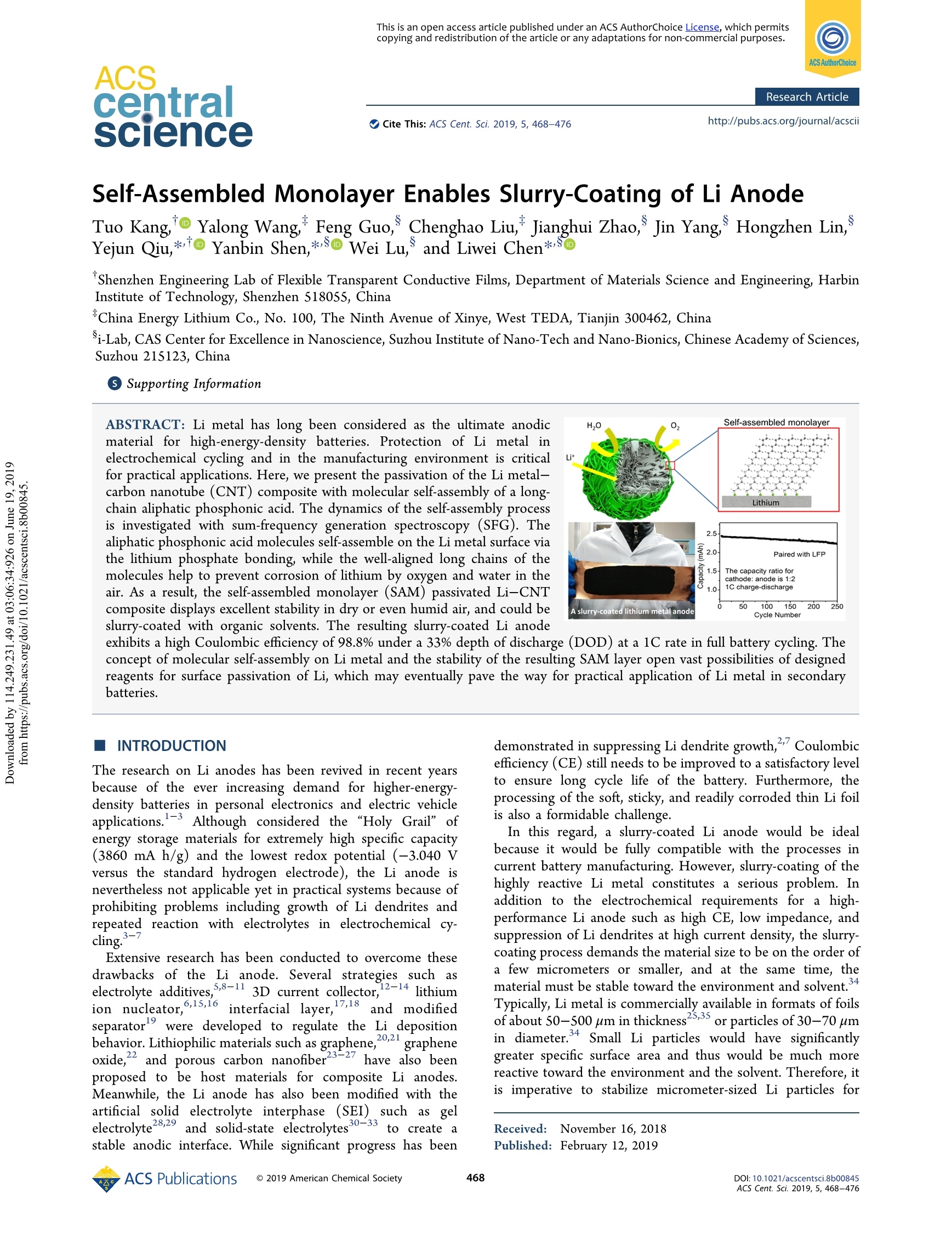
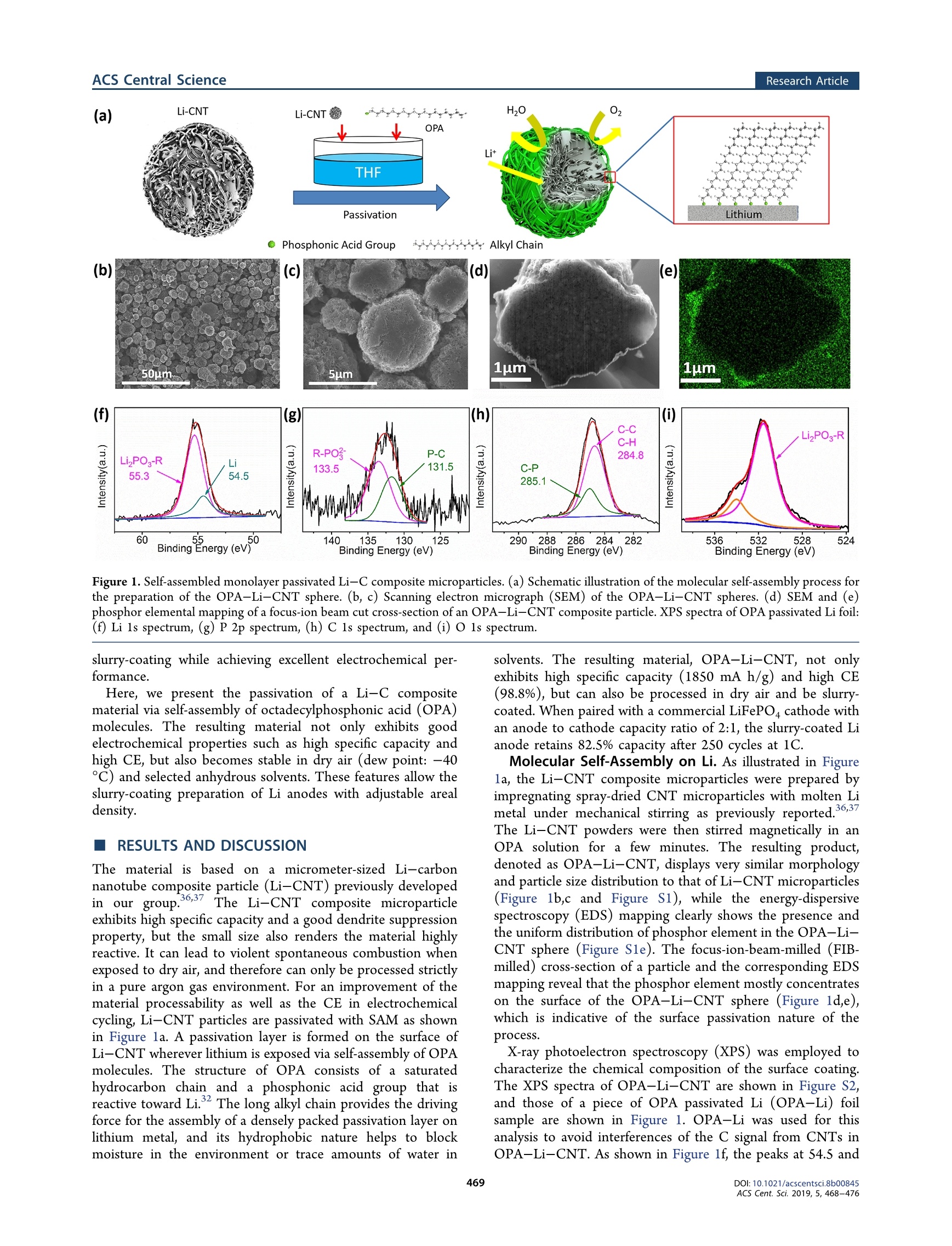
This is an open access article published under an ACS AuthorChoice License,which permitscopying and redistribution of the article or any adaptations for non-commercial purposes.ACScentralSCienceResearch Article) Cite This: ACS Cent. Sci. 2019, 5, 468-476 Research ArticleACS Central Science http://pubs.acs.org/journal/acscii Self-Assembled Monolayer Enables Slurry-Coating of Li Anode Tuo Kang,o Yalong Wang,Feng Guo, Chenghao Liu, Jianghui Zhao, Jin Yang, Hongzhen Lin,Yejun Qiu,*to Yanbin Shen*So Wei Lu, and Liwei Chen*so 'Shenzhen Engineering Lab of Flexible Transparent Conductive Films, Department of Materials Science and Engineering, HarbinInstitute of Technology, Shenzhen 51805S, China China Energy Lithium Co., No. 100, The Ninth Avenue of Xinye, West TEDA, Tianjin 300462, China Si-Lab, CAS Center for Excellence in Nanoscience, Suzhou Institute of Nano-Tech and Nano-Bionics, Chinese Academy of Sciences,Suzhou 215123, China Supporting Information ABSTRACT: Li metal has long been considered as the ultimate anodicmaterial for high-energy-density batteries. Protection of Li metal inelectrochemical cycling and in the manufacturing environment is criticalfor practical applications. Here, we present the passivation of the Li metal-carbon nanotube (CNT) composite with molecular self-assembly of a long-chain aliphatic phosphonic acid. The dynamics of the self-assembly processis investigated with sum-frequency generation spectroscopy (SFG). Thealiphatic phosphonic acid molecules self-assemble on the Li metal surface viathe lithium phosphate bonding, while the well-aligned long chains of themolecules help to prevent corrosion of lithium by oxygen and water in theair. As a result, the self-assembled monolayer (SAM) passivated Li-CNTcomposite displays excellent stability in dry or even humid air, and could beslurry-coated with organic solvents. The resulting slurry-coated Li anode INTRODUCTION The research on Li anodes has been revived in recent yearsbecause of the ever increasing demand for higher-energy-density batteries in personal electronics anhd e“lepctric vehicleapplications.3 Although considered the "Holy Grail" ofenergy storage materials for extremely high specific capacity(3860 mA h/g) and the lowest redox potential (-3.040 Vversus the standard hydrogen electrode), the Li anode isneverthelesess sn onto ta applicable yet in practical systems because of highprohibiting problems including growth of Li dendrites andrepeated reaction with electrolytes in electrochemical cy-cling.7 Extensive research has been conducted to overcome thesedrawbacks of the Li anode. Several strategies such aselectrolyte additives,,8-11 3D current collector, 2-14 lithiumion nucleator,6,15,16interfacial layer, 7,18and modifiedseparatorwere developed to regulate the Li depositionbehavior. Lithiophilic materials such as graphene,20.21grapheneoxide, and porous carbon nanofiber23-27have also beenproposed to be host materials for composite Li anodes.Meanwhile, the Li anode has also been modified with theartificial solid electrolyte interphase (SEI)) such asgelelectrolyte28.29and solid-state electrolytes30-33to create astable anodic interface. While significant progress has been demonstrated in suppressing Li dendrite growth,Coulombicefficiency (CE) still needs to be improved to a satisfactory levelto ensure long cycle life of the battery. Furthermore, theprocessing of the soft, sticky, and readily corroded thin Li foilis also a formidable challenge. In this regard, a slurry-coated Li anode would be idealbecause it would be fully compatible with the processes incurrent battery manufacturing. However, slurry-coating of thehighly reactive Li metal constitutes a serious problem. Inaddition to the electrochemical requirements for a high-performance Li anode such as high CE, low impedance, andsuppression of Li dendrites at high current density, the slurry-coating process demands the material size to be on the order ofa few micrometers or smaller, and at the same time, thematerial must be stable toward the environment and solvent.Typically, Li metal is commercially available in formats of foilsof about 50-500 um in thickness25,35 or particles of 30-70 umin diameter.4 Small Li particles would have significantlygreater specific surface area and thus would be much morereactive toward the environment and the solvent. Therefore, itis imperative to stabilize micrometer-sized Li particles for ( Re c e i ved:: N ovember 16, 2018 ) ( P ublish e d: F ebruary 12, 2 019 ) ACS Publications Li-CNT H20 (a) Li-CNT OPA Lit THF R-PO3 P-C 284.8 LizPO-R 133.5 131.5 55.3 285.1 60 .55 50 140 135 130 125 290o2882866284282 536 532 528 524 Binding Energy (eV) Binding Energy (eV) Binding Energy (eV) Binding Energy (eV) Figure 1. Self-assembled monolayer passivated Li-C composite microparticles. (a) Schematic illustration of the molecular self-assembly process forthe preparation of the OPA-Li-CNT sphere. (b, c) Scanning electron micrograph (SEM) of the OPA-Li-CNT spheres. (d) SEM and (e)phosphor elemental mapping of a focus-ion beam cut cross-section of an OPA-Li-CNT composite particle. XPS spectra of OPA passivated Li foil:(f) Li 1s spectrum, (g) P 2p spectrum, (h) C 1s spectrum, and (i) O1s spectrum. slurry-coating while achieving excellent electrochemical per-formance. Here, we present the passivation of a Li-C compositematerial via self-assembly of octadecylphosphonic acid (OPA)molecules. The resulting material not only exhibits goodelectrochemical properties such as high specific capacity andhigh CE, but also becomes stable in dry air (dew point: -40C) and selected anhydrous solvents. These features allow theslurry-coating preparation of Li anodes with adjustable arealdensity. RESULTS AND DISCUSSION The material is based on a micrometer-sized Li-carbonnanotube composite particle (Li-CNT) previously developedin our group.36,37 The Li-CNT composite microparticleexhibits high specific capacity and a good dendrite suppressionproperty, but the small size also renders the material highlyreactive. It can lead to violent spontaneous combustion whenexposed to dry air, and therefore can only be processed strictlyin a pure argon gas environment. For an improvement of thematerial processability as well as the CE in electrochemicalcycling, Li-CNT particles are passivated with SAM as shownin Figure la. A passivation layer is formed on the surface ofLi-CNT wherever lithium is exposed via self-assembly of OPAmolecules. The structure of OPA consists of a saturatedhydrocarbon chain and a phosphonic acid group that isreactive toward Li. The long alkyl chain provides the drivingforce for the assembly of a densely packed passivation layer onlithium metal, and its hydrophobic nature helps to blockmoisture in the environment or trace amounts of water in solvents. The resulting material, OPA-Li-CNT, not onlyexhibits high specific capacity (1850 mA h/g) and high CE(98.8%), but can also be processed in dry air and be slurry-coated. When paired with a commercial LiFePO4 cathode withan anode to cathode capacity ratio of 2:1, the slurry-coated Lianode retains 82.5% capacity after 250 cycles at 1C. Molecular Self-Assembly on Li. As illustrated in Figurela, the Li-CNT composite microparticles were prepared byimpregnating spray-dried CNT microparticles with molten Limetal under mechanical stirring as previously reported.,6,37The Li-CNT powders were then stirred magnetically in anOPA solution for a few minutes. The resulting product,denoted as OPA-Li-CNT, displays very similar morphologyand particle size distribution to that of Li-CNT microparticles(Figure 1b,c and Figure S1), while the energy-dispersivespectroscopy (EDS) mapping clearly shows the presence andthe uniform distribution of phosphor element in the OPA-Li-CNT sphere (Figure Sle). The focus-ion-beam-milled (FIB-milled) cross-section of a particle and the corresponding EDSmapping reveal that the phosphor element mostly concentrateson the surface of the OPA-Li-CNT sphere (Figure 1d,e),which is indicative of the surface passivation nature of theprocess. X-ray photoelectron spectroscopy (XPS) was employed tocharacterize the chemical composition of the surface coating.The XPS spectra of OPA-Li-CNT are shown in Figure S2,and those of a piece of OPA passivated Li (OPA-Li) foilsample are shown in Figure 1. OPA-Li was used for thisanalysis to avoid interferences of the C signal from CNTs inOPA-Li-CNT. As shown in Figure lf, the peaks at 54.5 and Figure 2. Dynamics study of the self-assembly process. Sum-frequency generation (SFG) vibrational spectra of the OPA assembly on a Li foilsurface. (a) CH stretch region, and (b) OH stretch region. (c-e) Schematic illustration of the molecular self-assembly process. 55.3 eV in the Li 1s spectrum are assigned to lithium andlithium phosphate in OPA-Li,respectively.38,39 The peaks at133.5 and 131.5 eV in the P 2p spectrum are assigned to P inP-O and P-C bonds, respectively (Figure 1g)3940 The peaksat ~285.0 and 284.8 eV in the C 1s spectrum are usuallyassigned to C in C-P, C-C, or C-H bonds that are hardlydistinguishable (Figure 1h).41.42 The major peak at 531.5 eV inthe O 1s spectrum is assigned to O in phosphates (Figure1i).43 The small sideband at 534 eV is similar to that in aprevious study, which was interpreted as being from impuritiesor contaminations (Figure 1i). These results indicate that thecoating layer on the Li surface is likely composed of lithiumalkyl phosphate. It is worth noticing that the Li 1s and the P 2pspectra of the OPA-Li-CNT (Figure S2e,f) are essentiallyidentical to those of OPA-Li foil in Figure lf,g, clearlyindicating the presence of the OPA layer. However, the C 1sand O 1s spectra are masked by high backgrounds from carbonnanotubes (Figure S2g,h). The dynamics of the self-assembly process is investigatedwith sum-frequency generation spectroscopy (SFG). SFG is aninterfacial vibrational spectroscopy with a selection rulerequiring that its signal arises from regions with brokencentrosymmetry only, and thus has been widely used instudying molecular self-assembly processes such as alkyl thiolson gold,14,4545alkyl silane and alkyl phosphonic acid onsilica.:46,47and alkyl capping ligandss on nanoparticlesurfaces.48,49 Model samples of Li foil immersed in OPAsolution for different times were rinsed and dried beforemeasurement. The SFG vibrational spectra in the C-H andO-H stretching regions are shown in Figure 2a,b, respectively. The SFG spectra were recorded with the ssp polarizationconfiguration. The characteristic vibrational modes at the C-H stretching region are methylene symmetric stretching(CH,(ss))) at28555 cm-, methyl symmetric stretching(CHg(ss)) at 2881 cm-, and their corresponding methyleneFermi resonance modes (CH,(FR)) at 2910 cmand methylFermi resonance (CH,(FR)) at 2940 cm-l, respectively.48.49The series of Li foil samples treated with OPA for different times show a clear trend in both symmetric stretch and Fermiresonance modes in which the methylene signal appears firstand then decreases, while the signal from the methyl groupbuilds up as the methylene signal diminishes. Such a behavior is fully consistent with previously reportedmolecular self-assembly processes of alkyl reagents. During theearly stage of the assembly (~10 min, Figure 2d), OPAmolecules are anchored to the Li surface via the lithiumphosphate bonding, which raises the signals from CH(ss) andCH (FR) modes since the quantity of methylene chains at theLi surface increases. In the meantime, the surface density ofOPA is low at this early stage, which allows a large degree offreedom for the octadecyl chain conformation, and therefore,the orientation of the terminal methyl group is randomized;thus, the signals from the methyl group are rather weak. As theSAM formation process proceeds, a higher density of OPAmolecules on the Li surface leads to a densely packed SAM.The octadecyl chain becomes fully extended, and theneighboring methylene groups point to opposite directions;however, the terminal methyl groups are all aligned at the sametilt angle (Figure 2e). Therefore, the signals from methylenegroups cancel out, but those from methyl groups build up. Thefact that the ratio of CH,(FR) over CH,(FR) remains constantafter 30 min indicates that the SAM formation is probablycompleted at 30 min. The major features observed in the O-H stretching regioninclude the broad band at around 3300 cm, the relativelysharp peak at about 3010 cm, and the weak broad band at3100 cm. It is well-accepted that the O-H stretchingfrequency reflects the local hydrogen bonding structure. The3300 cm-band is similar to that observed for bulk water andmost likely originates from the physically absorbed multilayerwater, while the peak at 3010 cm-, corresponding to OHgroups with stronger hydrogen bonding, can be assigned towater species in close vicinity of the metal surface. Such OHgroups may exist in a chemically reacted or strongly boundform, such as LiOH·H,O.2 Figure2b reveals that there existboth strongly bound water and weakly adsorbed water on the Figure 3. Environmental stability of SAM passivated Li-C microparticles. Digital photographs of pouring different powder samples in a dry-airenvironment (dew point: -40℃):(a) Li-CNT, (b) PA-Li-CNT, and (c)OPA-Li-CNT. XPS spectra of pristine and dry-air (dew point: -40°℃) exposed samples: (d) Li-CNT, (e) PA-Li-CNT, and (f) OPA-Li-CNT. (g) Electrochemical delithiation voltage profiles of pristine anddry-air exposed samples. (h) Electrochemical delithiation voltage profiles of the OPA-Li-CNT exposed to dry air for long hours. (i)Electrochemical delithiation voltage profiles of the OPA-Li-CNT after exposure to humid air (15℃, 50% RH) for long hours. pristine Li surface and Li surfaces with incomplete OPA SAM.However, both the 3010 and 3300 cmbands disappear as adensely packed SAM is formed after 30 min, indicating that thesurface hydroxide groups have reacted with OPA phosphonicgroups, and a weakly adsorbed water layer has been expelled bythe octadecyl chain as a result of the hydrophobic-interaction-driven self-assembly process. The weak broad band at around3100 cm-, which dominates upon the complete formation ofOPA SAM, can be readily attributed to the OH groups broughtby the OPA molecules. The expelling of water from the OPASAM is crucial in improving the environmental stability andprocessability of the Li-C composite materials. Environmental Stability and Processability. The SAMpassivated Li-C composite material OPA-Li-CNT exhibitsexcellent environmental stability and processability that arecompletely compatible with the current practice of batterymanufacturing. It can be safely processed in dry air. Figure 3a-c shows photographs of three different powder samples beingpoured down in a dry-air environment with a -40 ℃ dewpoint. Untreated bare Li-CNT material reacts violently withdry air and spontaneously bursts into flames (Video S1). Acontrol sample phosphoric acid passivated Li-CNT (PA-Li-CNT), which is Li-CNT treated with phosphoric acid, reactswith dry air less violently but still burnt red with heat intoashes(Video S2). In sharp contrast, the OPA-Li-CNT displays no apparent reaction under the same condition (VideoS3). Furthermore, the OPA-Li-CNT is also completely stablein air with 50% relative humidity (Video S4). These resultsindicate that the densely packed hydrophobic layer ofoctadecyl SAM is critical in sealing off moisture, oxygen, andnitrogen from Li metal. The stability of the OPA-Li-CNT in dry air is furtherconfirmed with XPS, X-ray diffraction (XRD), and SEM. TheLi 1s spectra in Figure 3d show that the Li element at thesurface of the Li-CNT before exposure to dry air i+s essentiallyall Li metal (54.5 eV). After 1 h of exposure to dry air, amajority of surface Li metal is oxidized into Li,O (55.8 eV).The XRD pattern of the samples also indicates that themajority of the bulk Li metal has been oxidized into LizO(Figure S3a). SEM shows that, after exposure to dry air for 1 h,the smooth morphology of the Li-CNT became irregular withgrains (Figure S4a,d). The XPS spectra of both the OPA-Li-CNT and the control sample PA-Li-CNT display a majorcomponent of lithium phosphate (55.3 eV)3 and a minorcomponent of Li metal before exposure. After 1 h of exposureto dry air the majority component at the surface of the PA-Li-CNT becomes Liz, and the relative quantity of lithiumphosphate is much reduced (Figure 3e). The XRD pattern ofPthe A-Li-CNT indicates that the majority of Li metal in thebulk is preserved, but the presence of Li,O is clearly made Figure 4. Slurry-coated lithium anode. (a) Digital photograph and (b) SEM micrograph of a slurry-coated lithium anode with areal capacity of 2.5mA h/cm (the coating area shown is ~8 cm in width and ~15 cm length). Voltage profiles during Li stripping/plating cycles of LillLi, Li-CNTIILi-CNT and slurry-coated OPA-Li-CNTIIOPA-Li-CNT cells in an ether-based electrolyte at current density of (c) 1 mA/cm and (d) 3 mA/cm. (e) Cycle performances of an OPA-Li-CNTIILFP coin cell. (f) Voltage profiles at different cycles of the OPA-Li-CNT||LFP coin cellcharged/discharged at 1C (1C =170 mA h/g). evident (Figure S3b). The SEM result shows that amorphological change of the PA-Li-CNT after exposure todry air is much less severe compared to the Li-CNT (FigureS4b,e). By contrast, the XPS spectra indicate that the surface ofthe OPA-Li-CNT is largely unchanged with only very littleamount of Li metal converted to Li,O (Figure 3f), and there isvirtually no LizO detected in the bulk of the OPA-Li-CNTvia XRD after 1 h of exposure in dry air (Figure S3c);moreover, there is almost no morphological change after 1 h ofexposure in dry air (Figure S4c,f). The effect of OPA on theenvironmental stability of Li metal foil was also studied forcomparison. The Li 1s spectra in Figure S5a confirmed thatlithium metal at the surface of lithium foil has been partiallyoxidized into Li,O after 60 min of exposure in dry air (dewpoint: -40℃). In contrast, the OPA passivated Li foilmaintains its surface chemical composition with only a traceamount of Li,O detected after the same exposure to the dry-airenvironment (Figure S5b). The electrochemical delithiation test is used to quantify thematerial stability. Various samples are pressed onto copperfoam and directly used as electrodes for delithiation experi-ments. As shown in Figure 3g, the delithiation potentials of the samples are all at 10 mV versus Li/Lit, the same as pure Lifoils. The delithiation capacity of Li-CNT is 2070 mA h/g,and those of PA-Li-CNT and OPA-Li-CNT are 1843 and1890 mA h/g, respectively. The slight reduction in specificcapacity is probably due to surface reaction of Li with PA andOPA. After exposure to dry air (dew point: -40 °C) for 1 h,the specific capacity of Li-CNT, PA-Li-CNT,and OPA-Li-CNT becomes 885, 1317, and 1790 mA h/g, correspond-ing to specific capacity retention of 42.7%, 71.4%, and 94.7%,respectively. The OPA-Li-CNT sample is particularly stable.It displays a delithiation capacity of 1734 and 1705 mA h/gafter 72 h and 1 week, respectively, in dry air (Figure 3h).OPA-Li-CNT can even withstand humid air (15 C, 50%RH): the delithiation capacity is observed to be 1685 mA h/gafter exposure to humid air for 2 h and 1050 mA h/g after 72 h(Figure 3i). Such high Li storage capacity, high stability, andexcellent processability provide a solid foundation for exploringthe electrochemical performance of the OPA-Li-CNTtoward practical applications. Slurry-Coated Lithium Anode. In spite of the smallparticle size (~5um), the OPA-Li-CNT is stable in dry airand selected anhydrous solvents thanks to SAM passivation, which enables the slurry-coating preparation of Li anodes withcontrollable areal mass loading. As shown in Figure 4a, anOPA-Li-CNT anode has been slurry-coated on a Cu foilcurrent collector with areal capacity of 2.5 mA h/cm’ (thethickness is measured to be ~200 um, Figure S7), using SBR/PS (10 wt %) as binder, AB (10 wt%) as electronic conductingadditive, and p-xylene as solvent. SEM images in Figure 4bshow that the OPA-Li-CNT particles maintain theirspherical shap,e and the XPS spectra in Figure S6b showedno chemical composition changes on the surface of the OPA-Li-CNT after slurry-coating. The electrochemical performance of the slurry-coatedOPA-Li-CNT anode was tested in a symmetric OPA-Li-CNTIIOPA-Li-CNT cell cycled in an ether-based electrolyteconsisting of 1 M LiTFSI in a solvent mixture of DOL/DME(DOL,1,3-dioxolane; 1:1 vol %). Symmetric cells of Li-CNTIILi-CNT using Cu foam-based Li-CNT electrodes and LillLiusing lithium foil as electrodes are assembled and measured forcomparison. The Li-CNT electrode was made using Cu foamas current collector but not slurry-coating since it reacts withthe solvent and yields LizCOs (Figure S6a). Although a self-assembled alkyl layer may be expected tohinder the Li stripping/platting, the OPA-Li-CNTIIOPA-Li-CNT cell exhibited a smaller and more stable over-potential. When cycled at a current density of 1 mA/cm(Figure 4c), the OPA-Li-CNTIIOPA-Li-CNT cell ex-hibited an overpotential of ~25 mV (FigureS8a) at thebeginning of the cycling, and the value slowly increase to ~45mV in 200 cycles (Figure S8c). In sharp contrast, the Li-CNTIILi-CNT cell showed an overpotential of ~60 mV at thebeginning of the cycling (Figure S8a), and then, the value rosequickly to ~95 mV within the first 200 cycles (Figure S8c).The LillLi cell demonstrated a typical stripping/platingbehavior of lithium metal, which showed an overpotential of~75 mV at the beginning of the cycling (Figure S8a) whichthen drops to 70 mV after 100 cycles (Figure S8b) because ofthe increase of surface area contributed by lithium dendrite;then, the value rose quickly, and the overpotential reached~175 mV at the end of 200 cycles (Figure S8c). At a highercurrent density of 3 mA/cm² (Figure 4d), greater overpotentialvalues were observed for all three cells. However, theoverpotentials of the OPA-Li-CNTIOPA-Li-CNT andLi-CNTIILi-CNT cell were much more stable compared tothat of the LillLi cell during 200 cycles. It is worth noting thatthe depth of discharge (DOD) of Li stripping/platting is 20%for the Li-CNTIILi-CNT and OPA-Li-CNTIIOPA-Li-CNT cell, while the DOD of the LillLi cell (thickness of thelithium foil: 100 um) is only 3% since it is difficult to prepare avery thin lithium foil. The electrochemical stability of the OPA-Li-CNT wasconfirmed with electrochemical impedance spectroscopy (EIS)measurements. As shown in the Nyquist plots in Figure S9, theimpedance of the Li foilllLi foil cell first decreased from 40 to27 after 50 cycles, which could be attributed to the increaseof specific surface area of the lithium electrode due to dendritegrowth. Then, the impedance increased drastically to ~110 Qafter 200 cycles, which could be attributed to the aggregationof “dead”lithium. The impedance of the Li-CNTIILi-CNTcell slowly increased from ~25 to ~50 at the 200th cycle. Insharp contrast, the impedance of the OPA-Li-CNTIIOPA-Li-CNT cell remained relatively stable and increased by only~8 Q in 200 cycles, indicating that the OPA layer can preventthe electrolyte from reacting with Li to form a high-impedance SEI. Furthermore, the stability of the OPA SAM layer inorganic electrolyte was also investigated by measuring theevolution of impedance spectra over storage time. As shown inFigure S10, the impedance of Li-CNT increased dramaticallyfrom ~20 to ~100 over 120 h of storage, while theimpedance of the OPA-Li-CNT symmetric cell increasedslowly from ~30 to ~50 over the same storage time.Considering the local curvature of the OPA-Li-CNTparticles, the increase in impedance could be attributed tothe imperfect coverage of lithium by OPA. Thus, the OPASAM layer is stable and does not dissolve in organicelectrolyte. The protective effect of the OPA SAM layer during cycling isfurther investigated via comparison of postmortem SEMimages against those of lithium metal foil and Li-CNTelectrodes. Figure S11 shows that, after 200 cycles, coarsefilament-like dendrites several um in size were observed on theLi foil electrode. Li-CNT particles maintained their sphericalshape after 200 cycles without any dendrites, but the particlesappeared to be covered with a new layer. In contrast, themorphologies of OPA-Li-CNT particles were well-main-tained after 200 cycles without apparent dendrites or extracoating, indicating that the OPA layer had protected thedecomposition of electrolyte on the surface of the Li-CNT toa good extent. These electrochemical behaviors of the OPA-Li-CNT material suggest that the OPA SAM layer not onlyleads to excellent environmental stability and processability butmay also improve the CE toward practical applications. Uponpairing with a LiFePO4 cathode (1.25 mA h/cm, the diameterof the electrode is 15 mm) to form a full cell at a cathode toanode capacity ratio of 1:2 and cycled at 1C between 2.5 and4.1 V in an ether-based electrolyte, more than 250 stable cycleswere recorded before rapid capacity decay started (Figure 4e).Taking this point as the complete consumption of the lithiumfrom the anode, a CE of ~98.8% is calculated (for details ofthe calculation, please refer to the SI). This CE of the slurry-coated Li anode is ~4.8% higher than that of the Li-CNTanode prepared by pressing the powders on a copper foam and~6.3% higher than that of the conventional Li foil anodemeasured at the same condition.36,37Figure 4f shows thevoltage profiles of the OPA-Li-CNTILFP cell at variouscycles. Even though the capacity of the cell gradually decreaseswith cycling, the overpotential of the voltage profiles keepsalmost constant at ~80 mV during cycling, which indicatesgood stability of the OPA-Li-CNT material in the LFP fullbattery. Li metal materials, if successfully utilized in batteries, can bedeployed as the lithiation reagent in lithium ion batteries tocompensate for the irreversible loss of capacity in the initialcycle, or they can be paired with lithium-free cathodes in“beyond lithium ion"battery chemistries such as Li-S and Li-O. Ideal Li metal materials for practical utilization not onlyshall display excellent electrochemical performances requiredby their respective applications, but also need to fulfill thefollowing additional requirements: (1)The production, includ-ing the fabrication of the host material and the subsequentlithiation of the host, needs to be scalable to industrialquantities and also cost-effective. (2) While the production ofLi metal materials may take place in Ar environment, they needto be safe and processable in a dry-air environment, which is astandard in the battery manufacturing industry. (3) Theutilization of the material should be compatible with thecurrent battery manufacturing processes. Our results show that a long-chain aliphatic SAM passivationlayer can effectively protect reactive Li metal materials fromwater, oxygen, and electrolyte, and at thesame timeconducting Li ion. Consequently, the OPA-Li-CNT materialcan be safely handled in dry or even humid air and could beslurry-coated with organic solvents. Since the raw materialsused for preparing the OPA-Li-CNT material (i.e., CNT andOPA) are available in large quantities and low cost, and themanufacturing techniques, i.e., spray drying of CNTdispersion, the molten impregnation for prelithiation of theCNT microspheres, and the OPA passivation of Li-CNT, arePA1all scalable, this material has a good chance for potentialapplications. Further research on the improvement of CE viastabilization of the SAM in electrochemical cycling is currently.underway. CONCLUSION In conclusion, we have demonstrated the molecular self-assembly of OPA passivated layer on a highly reactive Li-CNT composite microsphere to address its safety, environ-mental stability, and processability issues. SFG was used toinvestigate the dynaminVics of the self-assembly process. Theresulting OPA-Li-CNT material displays excellent environ-mental stability while significantly improving the electro-chemical performance. It is stable in dry air and can even beexposed to 50% humid air without catching fire. Suchrobustness allows the material to be processed into anodesusing the conventional slurry-coating procedure with organicsolvents. When the slurry-coated OPA-Li-CNT electrode ispaired with an LFP cathode at a 1:2 cathode to anode capacityratio, over 250 stable cycles were observed, which correspondsto a CE of 98.8%. The study of molecular self-assembly for Limetal passivation may also provide inspiration to thedevelopment of other alkaliirmetal materials for batteryapplications. METHODS Preparation of CNT Particles. In a typical synthesis ofCNT particles, 10.0 g of CNT (Shandong Dazhan NanoMaterials Technology Co., Ltd. GT-400) was dispersed in amixture of 1000 mL of ethanol and 100 mL of deionized water,and then ultrasonicated for 2 h. The obtained CNT suspensionwas then dried using a spray dryer. The inlet and outlettemperatures of spray dryer were fixed at 473 and 373 K,respectively, and the flow rate of air was maintained at 5 L/minat a feeding speed of 500 mL/h. Subsequently, the CNTparticles were collected from collector of the spray dryer. Preparation of Li-CNT Composite. The Li-CNTcomposite was prepared in an Ar-filled glovebox by mixing 4g of Li foil and 2 g of CNT particles in a 200 mL reactor madeof stainless steel. The temperature of the reactor was raised to493 K. Then, the molten Li and CNT particles weremechanically mixed for 20 min, and naturally cooled toroom temperature. The obtained Li-CNT composite wasfurther used to prepare the OPA-Li-CNT composite. Preparation of OPA-Li-CNT Composite. In a typicalsynthesis of the OPA-Li-CNT composite, 200 mg of as-prepared Li-CNT was dispersed in 20 mL ofa 0.1 wt % OPAin tetrahydrofuran (THF) solution by magnetic stirring forseveral minutes. The resultant solution was filtered after rinsingwith THF several times and dried at 333 K for 10 h undervacuum. Preparation of PA-Li-CNT Composite. In a typicalsynthesis of the OPA-Li-CNT composite, 200 mg of as-prepared Li-CNT was dispersed in 20 mL of a 0.1 wt % PA intetrahydrofuran (THF) solution by magnetic stirring forseveral minutes. The resultant solution was filtered afterrinsing with THF several times and dried at 333 K for 10 hunder vacuum. Materials Characterization. The sample morphology wascharacterized using an SEM instrument (Hitachi S-4800)operated at 3 kV. Li-CNT and Li foil electrodes weretransferred from a glovebox to an SEM chamber via a home-built gastight transfer device to protect the sample fromambient air. The chemical elements present in the sample wereanalyzed by EDS (Quanta FEG 250) operated at 20 kV. XPSspectra were taken with a Thermo Scientific ESCA Lab 250Xiinstrument using 200 W monochromated Al Ko radiation. Thesamples were transferred from an Ar-filled glovebox to the XPSmeasurement chamber in a custom-made XPS transferchamber with gastight sealing (Figure S12). The FIB millingand the corresponding SEM imaging of the cross-sectionsamples were conducted in a dual-beam Nova 200 NanoLabUHRFEG system. The SFG spectroscopy was carried out onan EKSPLA system with a copropagating configuration. TheXRD pattern of various samples was obtained on a Bruker D8diffractometer using Cu Ka radiation. Electrode Fabrication. For the powder press method, Li-CNT and OPA-Li-CNT powders were pressed on a round-shaped copper foam (1.75 cm in diameter and 600 um inthickness with the pore size of 60-70 um) and directly used aselectrodes. The areal capacity is ~20 mA h/cm. For the slurry-coating method, 20 mg of poly(styrene-co-butadiene) (SBR) (Sigma-Aldrich) and 20 mg of polystyrene(PS) (molecular weight:2 000 000, Alfa Aesar) were dissolvedin 1500 uL of p-xylene (anhydrous, 99.5%) (Sigma-Aldrich)followed by addition of 40 mg of acetylene black, and 320 mgof OPA-Li-CNT. After magnetic stirring for 10 h, the slurrywas coated with a doctor blade on a copper foil with the massloading (active material) of 2.5 mg/cm’, and then, theelectrodes were dried in a vacuum oven at 333 K for 10 h. Electrochemical Characterization. The 2025 type coincells were used to fabricate batteries for all electrochemicalmeasurements. Polypropylene membrane (Celgard 2400) wasused as the separator. The EIS measurements were performedon an RST 5000 electrochemical workstation (Suzhou RisetestElectronic Co., Ltd.) over the frequency range from 100 mHzto 100 kHz with an amplitude of 5 mV. Electrochemicalperformance was evaluated by a NEWARE battery analyzer(NEWARE technology Ltd., Shenzhen, China). Stripping/plating experiments were performed on symmetric cells of Lifoil, Li-CNT, and OPA-Li-CNT electrodes at 1 and 3 mA/cm" for 200 cycles, with each cycle involving a capacity of 0.5mA h/cm. The electrolyte consisted of 1 M LiTFSI in asolvent mixture of DOL/DME (1:1 vol %). In the full celltesting, OPA-Li-CNT electrode with a capacity of 2.5 mA h/cm and LFP (Sinlion Battery Tech, Co., Ltd.) electrode with acapacity of 1.25 mA h/cmwere used as anode and cathode,respectively. The electrolyte consisted of 1 M LiTFSI in asolvent mixture of DOL/DME (1:1 vol %) with 2 wt% LiNO,as additive Electrochemical Delithiation. For an evaluation of thespecific capacity of the OPA-Li-CNT composite, 25 mg ofthe OPA-Li-CNT composite was assembled in a LillOPA-Li-CNT battery. The battery was galvanostatically charged at a current density of 0.5 mA/cm’ until all of the lithium waselectrochemically stripped from the OPA-Li-CNT compo-site. ASSOCIATED CONTENT ⑤ Supporting Information The Supporting Information is available free of charge on theACS Publications website at DOI:10.1021/acscents-ci.8b00845. Calculation of Coulombic efficiency and additionalfigures including SEM images, diameter distributions,XPS spectra, XRD results, overpotentials, Nyquist plots,photograph, and schematics (PDF) Video S1: untreated bare Li-CNT material reactsviolently with dry air and spontaneously bursts intoflames (AVI) Video S2: PA-Li-CNT reacts with dry air less violentlybut still burns red with heat into ashes (AVI) Video S3: OPA-Li-CNT displays no apparent reactionunder the same conditions (AVI) Video S4: OPA-Li-CNT is also completely stable in airwith 50% relative humidity (AVI) AUTHOR INFORMATION Corresponding Authors *E-mail: yejunqiu@hit.edu.cn. *E-mail: ybshen2017@sinano.ac.cn. *E-mail:lwchen2008@sinano.ac.cn. ORCIDO Tuo Kang: 0000-0002-1868-3140 Yejun Qiu: 0000-0003-0519-0424 Yanbin Shen: 0000-0002-1278-1137 Liwei Chen: 0000-0003-4160-9771 Author Contributions L.C. conceived the original idea. T.K., Y.Q., Y.S., and L.C.designed all the experiments. T.K., Y.W., F.G., and W.L.prepared the samples. T.K. and J.Z. slurry-coated the OPA-Li-CNT electrodes. T.K. and C.L. performed the stability andelectrochemical tests. T.K., J.Y., and H.L. carried out the SFGcharacterization. T.K., Y.Q., Y.S., and L.C. wrote the paper. Allauthors were involved in analysis of the experimental data,discussion of the results, and tthhee ppireparation of themanuscript. Notes The authors declare no competing financial interest. Safety statement: Li-CNT particles spontaneously react withdry or moist air, and thus must be handled with care in Aratmosphere. OPA-Li-CNT can be processed in dry andmoist air. Waste Li-CNT and OPA-Li-CNT materials needto be slowly oxidized under controlled conditions beforedisposed as chemical wastes. ACKNOWLEDGMENTS This work was financially supported by the Ministry of Scienceand Technology (Grant 2016YFB0100102), thee“StrategicPriority ResearchhProgram" of the CASS((GrantsXDA09010600 and XDA09010303), and the National NaturalScience Foundation of China (Grants 21625304,21733012,and 21773290). ( REFERENC E S ) ( ( 1) G uo, Y.; L i, H.; Zhai, T. Reviving lithium-metal anodes for next- generation h igh-energy batteries. Adv. Mater. 2017,29, 17 0 0007. ) ( (2) L i n, D . ; L i u, Y.; C u i, Y . R e viving the lithium metal ano d e for high-energy batteries. Nat. Nanotechnol.2017, 12,194-206. ) ( ( 3) Y ang, C . ; F u , K . ; Zhang, Y.; Hitz, E . ; Hu, L. Protected lithium-metal a nodes i n batteries: from liquid t o solid. Adv. Mater. 2017, 2 9, 1701169. ) ( ( 4) C heng, X . B . ; Z h ang, R.; Zhao, C. Z.; We i , F.; Zhang, J. G.; Zhang, Q. A review of solid e l ectrolyte interphases on l i thium m e talanode. A dv. S ci. (Weinh) 2016, 3, 1500213. ) ( ( 5) Z hang, X .-Q.; Cheng, X .-B.; Chen, X.; Yan, C.; Zhang, Q.Fluoroethylene c arbonate additives t o render u niform li d eposits inlithium m etal batteries. Adv. Funct. Mater. 2017, 2 7, 1 605989. ) ( ( 6) Z hang, R.; C hen, X . R . ; Chen, X . ; Cheng, X. B.; Z h ang, X. Q; Yan,C.; Zhang, Q. Lithiophilic site s in doped graphene guide uniform lithium n ucleation f or d endrite-free l ithium m etal Anodes. Angew. Chem., I nt. Ed. 2017, 56 , 7764-7768. ) ( ( 7) C heng, X. B.; Z hang, R .; Zhao, C . Z .; Zhang, Q. Toward s a felithium metal a node in rechargeable batteries: a review. Chem. R ev. 2017, 1 17,10403-10473. ) ( ( 8) L u , Y . ; Da s, S . K . ; Moganty, S. S .; Archer, L. A . I oni c liqu i d-nanoparticle hybrid e lectrolytes and t heir application in secondary lithium-metal b atteries. Adv. Mater. 2 012 , 24, 4430-4435. ) ( (9) D ing, F .; Xu, W.; Graff, G. L.; Zhang, J. ; Sushko, M. L.; Chen,X.; Shao, Y.; Engelhard, M. H.;Nie, Z.; Xiao,J.; L i u, X.; Sushko, P.V.; Liu,J.; Zhang, J. G. Dendrite-free lithium deposition via self-healingelectrostati c shield mechanism. J. Am. Chem. Soc. 2013, 1 3S, 4450-4456. ) ( ( 10) Zhang, Y.; Qian, J.; Xu, W.; Russell, S. M. ; Chen, X.;Nasybulin, E.; Bhattacharya, P .; Engelhard, M . H . ; M e i, D.; Cao, R.; Di n g, F.; Cresce, A . V.; X u, K.; Zhang, J. G. Dendrite-free lithium depositionwith self-aligned nanorod structure.Nano Lett. 2014, 1 4 ,6889-6896. ) ( ( 11) Z heng, J . ; E ngelhard, M. H.; Mei, D. ; Jiao, S.; P o lzin, B. J.; Zhang, J.-G.; Xu, W. E lectrolyte additive enabled f ast charging and stable cycling lithium m etal batteries. Nature Energy 2 0 17, 2, 1 70 1 2. ) ( (12) L iu, W.; L i n, D.; Pe i , A. ; Cu i , Y. Sta b ilizing lithium met a l anodes b y uniform L i -ion flux d istribution in nanochannel confine- ment. J. Am. Chem. S oc. 2 016, 138, 15443-15450. ) ( (13) Y ang, C. P.; Y in, Y . X .; Zhang, S. F .; Li, N. W.; G uo, Y . G.Accommodating lithium in t o 3D current collectors with a submicronskeleton towards long-life lithium meta l anodes. Nat. Commun. 2015, 6,8058. ) ( (14) Y e , H. ; Xin, S.; Yin, Y. X.; Li, J. Y.; Guo, Y. G.; Wan, L. J. S ta b le Li plating/stripping electrochemistry realized by a hybrid Li reservoir in s pherical carbon granules w ith 3D conducting skeletons. J. Am. Chem. Soc.2017, 139,5916-5922. ) ( ( 15) Yang, C.; Yao, Y . ; H e, S.; X ie, H .; H itz, E .; Hu, L. Ultrafinesilver nanoparticles for seeded lithium d e position to w ard sta b lelithium metal anode. Adv. Mater. 2 017, 29, 1 702714. ) ( ( 16) Yan, K . ; Lu, Z.; Lee, H.-W.; Xiong, F.; Hsu, P. - C.; Li,Y.; Zhao,J.; Chu, S.; Cui, Y. S elective d eposition a n d st a ble en c apsulation of lithium through heterogeneous seeded growth. Nature Energy 2016, I,16010. ) ( (17) Liang, Z.; Z heng, G.; L i u, C . ; Liu, N.; Li, W .; Yan, K.; Y ao, H .;Hsu, P .-C.; Chu, S .; Cui, Y. P olymer n a nofiber-guided uniformlithium deposition for battery electrodes. Nano Lett. 201 5 , 15,2910- 2916. ) (18) Zheng, G.; Lee, S. W.; Liang, Z.; Lee, H. W.; Yan, K.; Yao, H.;Wang, H.; Li, W.; Chu, S.; Cui, Y. Interconnected hollow carbonnanospheres for stable lithium metal anodes. Nat. Nanotechnol.2014,9, 618-623. (19) Liu, Y.; Liu, Q.; Xin, L.; Liu, Y.; Yang, F.; Stach, E. A.; Xie, J.Making Li-metal electrodes rechargeable by controlling the dendritegrowth direction. Nature Energy 2017, 2, 17083. ( (20) Zhang, R. ; Ch e ng, X. B .; Zha o , C. Z . ; Peng , H. J.; Sh i , J . L.;Huang, J. Q.; Wang, J; Wei, F.; Zhang, Q. Conductive nanostructured s caffolds r ender l o w local c u rrent de n sity to inh i bit lithium den d ritegrowth. Adv. Mater . 2016,28,2155-2162. ) (21) Liu, S.; Wang, A.; Li, Q; Wu, J.; Chiou, K.; Huang, J.;Luo,JCrumpled graphene balls stabilized dendrite-free lithium metalanodes. Joule 2018, 2, 184-193. (22) Lin, D.; Liu, Y.; Liang, Z.; Lee, H. W.; Sun,J; Wang, H.; Yan,K.; Xie, J.; Cui, Y. Layered reduced graphene oxide with nanoscaleinterlayer gaps as a stable host for lithium metal anodes. Nat.Nanotechnol. 2016, 11, 626-632. ( (23) Z h ang, Y. ; Wang, C.; Pas t el, G.; Kua n g, Y.; Xie, H.; Li, Y.; Liu , B.; Luo, W.; C hen, C.; Hu, L . 3 D We t table framework for dendrite- free alkal i metal anodes. Adv. Energy Mater. 2018, 8, 1800635. ) ( (24) Liu, L.; Yin,Y.-X.; Li,J.-Y.; Li, N.-W.;Zeng, X.-X.; Ye, H.; Guo,Y.-G.; Wan, L .J. Free-standing hollow carbon fibers as high-capacitycontainers for stable lithiu m metal anodes. Joule 2017 , 1,563-575. ) ( (25) Z hang, R . ; C hen, X . ; S h en, X . ; Z h ang, X.-Q.; Chen, X. - R.; C heng, X . -B.; Yan, C.; Zhao, C.-Z.;Zh a ng, Q. Cor a lloid carbon fiber-based c omposite l i thium anode for robust lithium metal batteries.Joule 2018, 2,764-777. ) ( (26) L i u, Y.; L in, D.; L iang, Z.; Z hao,J. ; Y a n, K.; C u i, Y. Lithium-coated polymeric matrix as a minimum volume-change and dendrite- 11 11 1 1 free lithium metal anode. Nat. Commun. 2016,7, 1 0 992. ) ( (27) Lang, J; Jin, Y . ; L u o, X. ; Liu, Z. ; So n g, J.; Lo n g, Y.; Q i , L.; Fang, M .; L i, Z .; Wu, H. S u rface graphited carbon sc a ffold enablessimple and scalable f abrication of 3D composite lithium metal anode. J . Mater. Chem. A 2017, S, 19168- 1 9. ) ( (28) Z heng, G . ; Wang, C.; Pei , A.; Lopez, J.; Sh i , F. ; Ch e n, Z.;Sendek, A. D.; L ee, H .-W.; Lu, Z.; S chneider, H.; S afont-Sempere, M. M .; C hu, S.; Bao, Z.; Cui, Y. High-performance lithium metal negative e lectrode with a soft and flowable p o lymer coating. ACS Energy Letters 2016, 1 , 1 247-1255. ) ( (29) Wu, H.; Ca o , Y.; Ge n g, L.; Wang, C. In situ form a tion of st a ble i nterfacial coating for high performance lithium metal anodes. C h em. Mater. 2017, 29,3572-3579. ) ( (30) X ie, J.; Sendek, A. D.; Cubuk, E. D.; Zhang, X.; Lu, Z . ; Gong, Y .; Wu, T.; S h i, F.; L iu, W .; R e ed, E . J . ; C u i, Y . A t omic la y er d eposition of stable LiAlF, lithium ion conductive inter f acial layer forstable cathode cycling. AC S Nano 2017, 11 , 7019-7027. ) ( (31) Lin, D.; L iu, Y.; Chen, W.; Zhou, G.; Liu, K.; Dunn, B.; Cui, Y.Conformal lithium fl u oride p ro tection la y er on three-dimensionallithium by nonhazardous gaseous reagent freon. Nano Lett. 20 1 7, 17, 3731-3737. ) ( (32) L i , N. W.; Yin, Y. X.; Yang, C. P.; Gu o , Y. G. An artificial sol i d e lectrolyte interphase l ayer f or s table l ithium metal a n odes. Ad v . Mater. 2016, 28, 1853-1858. ) ( (33) Li, X .; Guo, S.; D eng, H . ; J iang, K.; Qiao, Y .; I shida, M.; Zhou, H. An ultrafast rechargeable lithium m etal battery. J. Mater. Chem. A2018, 6 ,15517-15522. ) ( (34) Ai, G .; W ang, Z.; Z h ao, H. ; Ma o , W.; Fu, Y.; Y i, R.; Ga o , Y.;Battaglia , V. ; Wang, D.; Lopatin, S .; Liu, G. S calable p rocess forapplication o f stabilized l ithium metal p o wder in L i- i on batteries. J. P ower Sources 2016, 309, 33-41. ) ( (35) R you, M . -H.; Lee, Y. M.; Lee, Y. ; Wi n ter, M.; Bie k er, P. Mechanical surface m odification o f lithium metal: towards improved Li metal anode performance by directed Li plating. Adv. Funct. Mat e r. 2015,25, 834-841. ) ( (36) Guo, F.; Wang, Y. ; Kang, T.; Li u , C.; S h en, Y.; Lu, W.; Wu, X.; C hen, L . A Li-dual c a rbon co m posite as s ta b le anode material for Li b atteries. Energy Storage Materials 2018, 15, 116-123. ) ( (37) Wang, Y.; Shen, Y.; D u, Z.; Zhang, X.; Wang, K.; Zhang, H. ; Kang, T.; G uo, F.; L iu, C.; Wu, X.; Lu, W.; Chen, L. A lithium-carbonnanotube composite f o r s t able lithium anodes. J . Mater. C hem. A 2017, S, 23434-23439. ) ( (38) Contour, J. P . ; Sa lesse, A .; F roment, M.; G ar reau, M. ; Thevenin, J.; Warin, D. Analysis b y electron-microscopy and xps oflithium s urfaces polarized i n a n hydrous org a nic electrolytes. Jou r nal De Microscopie Et De S p ectroscopie Electroniques 1 979, 4, 4 83-491. ) ( (39) M organ, W . E. ; St e c, W. J.; Va n wazer, J. R . Inn e r-orbital photoelectron spectroscopy of alk a li-metal hal i des, per c hlorates, p hosphates, and p yrophosphates. J. Am. C hem. Soc. 1973, 95, 7 5 1- 755. ) ( (40) S hul’ga, Y. M.; Bulatov, A. V.; Gould, R. A. T.; Konze, W.V.; Pignolet , L. H. X-ray p hotoelectron-spectroscopy of a s eries ofheterometallic gold platinum phosphine cluster c ompounds. Inorg. Chem. 1 992, 31,4704-4706. ) ( ( 41) Swiatowska, J.; Lair, V.; Pereira-Nabais, C.; Cote, G .; M arcus,P.; Chagnes, A. XPS, XRD a n d SEM cha r acterization of a t h in c e rialayer deposited onto graphite electrode fo r application in li t hium-ion b atteries. Appl. Surf . Sc i . 2011, 2S7 , 9110-9119. ) ( (42) Larsson, R.; Malek, A.; Folkesson, B. Ir intensity measurements on p henyl groups for esca ca l ibration an d the est i mation of effectivecharges applied to phosphorus-compounds. Chemica Scripta 1 9 80, 1 6 , 47-51. ) ( (43) D ang, T. A.; C hau, C. N. Electron spectroscopy for c hemicalanalysis of cool white p hosphors c o ated with Si O , thin fil m . J.Electrochem. Soc . 1996 , 143,302-305. ) ( ( 44) Yeganeh, M. S.; D o ugal, S. M.; Polizzotti, R. S.; Rabinowitz, P. 4) : Interfacial atomic s tructure o f a self-assembled alkyl thiol monolayer/ Au (11 1 ): A sum-frequency generation study. Phys . Rev. Lett . 199 5 , 74, 1811-1814. ) ( (45) Jacob,J. D. C . ; Le e , T. R .; Ba l delli, S. I n s i tu vibrational s t udy of the reductive desorption o f alkanethiol monolayers on g o ld by sumfrequency generation spectroscopy. J . Phys . Chem. C 2 014, 118, 29126-29134. ) ( (46) Dubey, M . ; W e idner, T. ; Ga m ble, L. J .; Cas t ner, D. G.Structure and order o f p hosphonic acid-based self-assembledmonolayers o n S i(100). Langmuir 2010, 26, 14747-14754. ) ( ( 47) L iu, Y.; Wolf, L. K.; Messmer, M . C. A s t udy of alkyl chainconformational c h anges in se l f-assembled n-o c tadecyltrichlorosilanemonolayers on fused silica surfaces . Langmuir 2001, 17, 4 329-4335. ) ( (48) Roke, S.; Berg, O.; B u itenhuis, J.; van B l aaderen, A.; Bonn, M.Surface molecular view of colloidal ge l ation. Proc. Natl. Acad. Sci. U. S. A. 2006,103, 1 3310-13314. ) ( ( 49) Z hang, H . ; L i , F.; Xiao, Q.; Lin, H. Conformation o f capping ligands o n nanoplates: f a cet-edge-induced disorder and self-assembly- related ordering revealed by sum frequency generation Spectroscopy.J. Phys . Chem. Lett. 2015, 6,2170-2176. ) ( ( S0) W eeraman, C . ;Yatawara, A. K . ; Bordenyuk, A . N . ; Benderskii,A. V. Effect of nanoscale geometry on m o lecular c o nformation: vibrationa l sum-frequency generation of a lkanethiols on goldnanoparticles. J . Am. Chem. Soc. 2006, 128, 14244-14245. ) ( (51) D aldrop, J . O.; Saita, M.; H eyden, M.; Lo r enz-Fonfria, V. A.; Heberle, J.; Netz, R. R. Orientation of non-spherical protonated waterclusters revealed by infrared absorption dichroism. Nat. Commun.2018,9,311. ) ( ( 52) Zhang, X . ; G u o, L.; Gan, L. ; Zhang, Y.; Wang, J.; Johnson, L.R.; Bruce, P. G.; Peng, Z. LiO: cr y o synthesis and che m ical/electrochemical reactivities. J. Phys. Chem. Lett. 2017, 8 ,2334-2338. ) American Chemical SocietyDOI:acscentsci.bCS Cent. Sci. , OI: acscentsci.bCS Cent. Sci. , Li metal has long been considered as the ultimate anodic material for high-energy-density batteries. Protection of Li metal in electrochemical cycling and in the manufacturing environment is critical for practical applications. Here, we present the passivation of the Li metal−carbon nanotube (CNT) composite with molecular self-assembly of a longchainaliphatic phosphonic acid. The dynamics of the self-assembly process is investigated with sum-frequency generation spectroscopy (SFG). The aliphatic phosphonic acid molecules self-assemble on the Li metal surface via the lithium phosphate bonding, while the well-aligned long chains of the molecules help to prevent corrosion of lithium by oxygen and water in theair. As a result, the self-assembled monolayer (SAM) passivated Li−CNT composite displays excellent stability in dry or even humid air, and could be slurry-coated with organic solvents. The resulting slurry-coated Li anode exhibits a high Coulombic efficiency of 98.8% under a 33% depth of discharge (DOD) at a 1C rate in full battery cycling. The concept of molecular self-assembly on Li metal and the stability of the resulting SAM layer open vast possibilities of designed reagents for surface passivation of Li, which may eventually pave the way for practical application of Li metal in secondary batteries.
关闭-
1/9
-
2/9
还剩7页未读,是否继续阅读?
继续免费阅读全文产品配置单
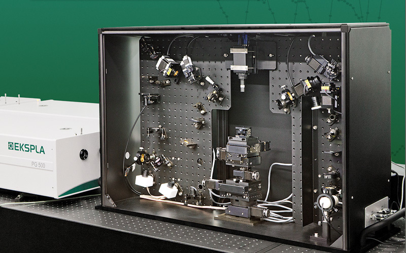
北京欧兰科技发展有限公司为您提供《锂阳极中和频光谱SFG检测方案(其它光谱仪)》,该方案主要用于锂电池中和频光谱SFG检测,参考标准《暂无》,《锂阳极中和频光谱SFG检测方案(其它光谱仪)》用到的仪器有Ekspla SFG 表面和频光谱分析系统。
我要纠错
推荐专场
其它光谱仪
更多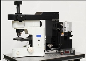
相关方案
 咨询
咨询