
我在故我思
第2楼2006/11/10
2.PDHID
PDHID的离子化方式是氦光离子化,高纯氦大约以30mL/min的速度从检测池顶部引入放电区,双原子氦跃迁到解离的2He(I's)基态时产生Hopfield的光离子发射。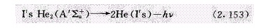
发射谱带是在70-90nm附近,能量在16-18eV,高能光子几乎可以把所有化合物离子化,除Ne以外有机、无机化合物都会有信号,因此是通用型检侧器(Ne的离子化势是21.5eV,接近He*亚稳态19.8eV,但大于He的连续光谱能,故信号很低),离子化效率是0.01%-0.1%,可属非破坏性检测器。
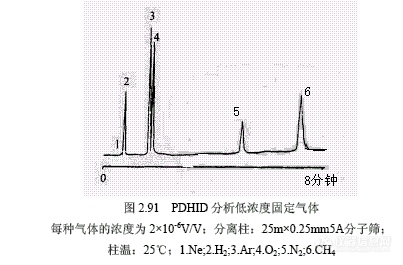
Wentworth等报道PDHID的最小可检度低至皮克级。图2.91所示为固定气体的分析实例,还给出了各种气体和174种化合物的相对信号因子。各类化合物平均熏量相对信号列于表2.26。
我在故我思
第3楼2006/11/10
3. PDECD
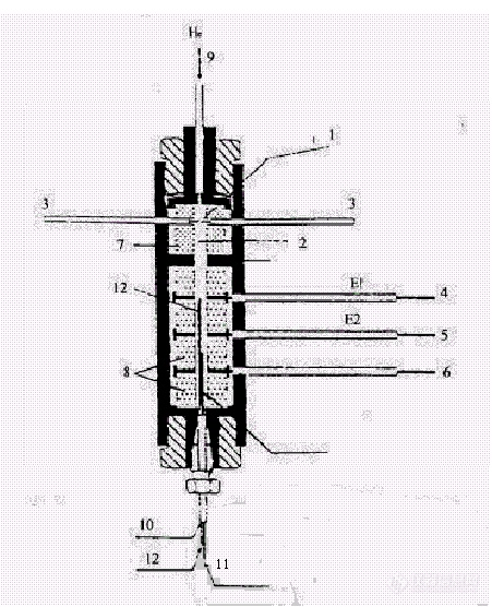
常用ECD主要缺点是由放射源引起的,存在的问题是:(1)安全;(2)放射源容易被分析物污染;(3)63Ni-ECD的活性表面和检测池体积较大,会产生峰扩张,对极性溶剂拖尾尤为严重,因此在1964年提出非放射源ECD,多年未能得到彻底解决。 PDECD是一种很好的非放射源工作方式,其工作原理是在靠近电离区的下游引入掺杂气,藉放电又产生的高能光子使掺杂气首先离子化,产生的电子藉两个偏电压向反应区聚焦,这样偏电极E1与E2间是电子形成区。在PDECD池内电子和正离子分布是不均匀的,因为用负偏压,正离子在偏压电极E1附近浓度最高,向收集极方向浓度逐渐减小;电子的分布则相反,在收集极电了浓度最大,到偏压电极E1电子浓度接近于零,E2与收集极问是电子俘获区。在收集极附近的电子产生基准电流I参考,当有负电性化合物从色谱柱流出就会俘获电子,基流减小I测,此改变脉冲频率产生信号。毛细管柱出口位于收集极上方0.4mm处,电子浓度最高,是电子俘获区,由于电子形成过程与电子俘获过程分开,很少发生干扰,这样可使正离子-电子相结合的机会减小。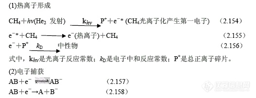
PDECD的掺杂气可以用甲烷、氢或氮,氢和氮的离子化能分别是15.4eV和15.6eV,对某些电子亲和力低或离子化能低的物质(如碳氢化合物)会离子化,CH4的电离势是12.6eV,比H2和N2的IP值低,可以减小外来离子化峰的干扰,灵敏度较高.甲烷以l%-5%浓度混在He中加人,流速约3-15mL/min,即检侧池中CH4在总He中的浓度保持在0.3%。产生基流约32nA。PDHID的基流约0.4nA。
我在故我思
第7楼2006/11/10
摘 要 研究本实验室组装的脉冲放电氦光离子化检测系统上PDPID 的性能、各种操作参数对信号的影响、操作最佳化及信号线性。用该系统分析了汽油、酮醇混合物和痕量挥发性有机化合物等样品,它们的色谱图可以同FID 相比。 脉冲放电氦光离子化检测器分析有机化合物的性能研究
我在故我思
第8楼2006/11/10
以下介绍几种PPD:
The Pulsed Discharge Electron Capture Detector
The pulsed discharge electron capture detector is an extension of the previously discussed pulsed discharge helium ionization detector, a diagram of which is shown in figure 44. The detector functions in exactly the same as that of the traditional electron capture detector but differs in the method of electron production. The sensor consists of two sections: the upper section has a relatively small diameter and is where the discharge takes place. The lower section has a much wider diameter and in this part of the sensor, the column eluent is sensed and electron capturing occurs. As with the pulsed discharge helium ionization detector, the potential across the electrodes is pulsed at about 3 kHz with a discharge pulse width of about 45 msec. The discharge produces electrons and high energy photons and some metastable helium atoms. The helium, doped with propane, enters just below the second electrode, metastable atoms are removed and electrons are generated both by the decay of the metastable atoms and by the photons. 
我在故我思
第9楼2006/11/10
The Simple or Macro Argon Detector Sensor
However, there are some complications to this apparently simple sensing system; when an ion is produced by collision between a metastable atom and an organic molecule, the electron, simultaneously produced, is immediately accelerated toward the anode. This results in a further increaseinmetastableatoms and a consequent increase in the ionization of the organic molecules. The resulting cascade effect, unless controlled, results in an exponential increase in ion current. The control of this cascade production of ions involves a negative feed back control on the ion production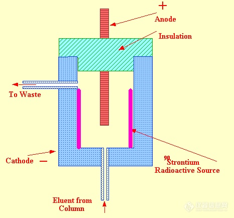
我在故我思
第10楼2006/11/10
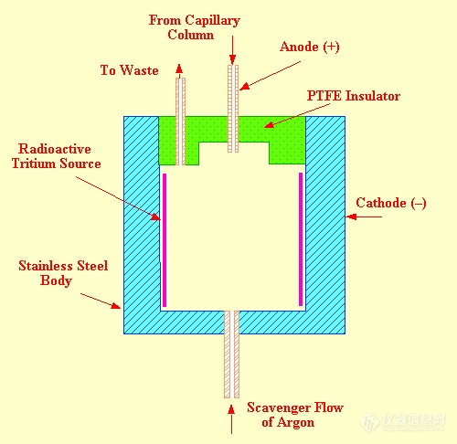
The Micro Argon Detector
A diagram of the micro argon detector sensor is shown in figure 29. This sensor is designed to have a very small "effective" sensing volume to facilitate its use with capillary columns where the flow rate may be as low as 0.1 ml/min or less. In the micro argon detector sensor, the anode is withdrawn into a small cavity about 2.5 mm in diameter. This ensures that the electrons can only reach the anode along a restricted path and the electric field around the electrode resides within a few diameters of the anode tip. The anode is tubular in form and the capillary column can slide up inside the anode until it is within a millimeter or so of the electric field. Metastable argon atoms are formed as a cloud of around the anode tip and any solute molecules eluted from the column immediately pass through this cloud and are ionized.