方案详情文
智能文字提取功能测试中
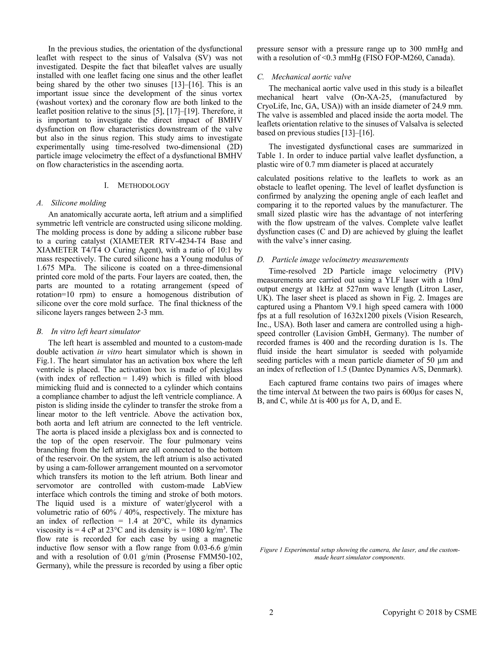
Proceedings of The Canadian Society for Mechanical Engineering International Congress 2018CSME International Congress 2018May 27-30, 2018, Toronto, On, Canada IN VITRO INVESTIGATION OF THE EFFECT OF A DYSFUNCTIONALBILEAFLETMECHANICAL AORTIC VALVE ON FLOW CHARACTERISTICS INTHE ASCENDING AORTA Ahmed Darwish *, Wael Saleh, Giuseppe Di Labbio, Lyes Kadem Mechanical, Industrial, and Aerospace Engineering Department Concordia University Montreal, QC, Canada *email:lcfd@encs.concordia.ca Mechanical Engineering Department Abstract-Heart valve replacement is still the optimal solutionin young patients with severe symptomatic heart valve disease.In those patients, bileaflet mechanical heart valves (BMHV)are preferred to biological valves because of their higherdurability. However, thrombus formation has been reported asacommoncomplicationfollowinggBMHV implantationdespitea permanentanticoagulationntherapy.Thrombusformation can llead to valve leaflet dysfunction, a life-threateningevent thatrequiresiimmediate: surgicalintervention. This study aims to investigate the fluid dynamicsdownstream of a dysfunctional bileaflet mechanical aorticvalve. A bileaflet ON-X mechanical aortic valve is used withdifferent dysfunctional configurations. In this study, partiallyand totally blocked configurations of one of the leaflets isinvestigated relative to its orientation with the sinus ofValsalva.i.TTime-resolvedtwo-dimensionalparticle imagevelocimetry measurements are performed to investigate flowfield characteristics in the ascending aorta in terms of velocityand vorticity fields and circulation. Vorticity and circulation inthe aorta are significantly affected by the valve orientationwith respect to the sinus of Valsalva. Bileaflet Mechanical Heart Valve: Particle ImageVelocimetry; Hemodynamics. I. INTRODUCTION Heart valve failure is a known cardiovascular disease wherevalves fail to open or close properly. A report from theAmerican Heart Association mentioned that the prevalence ofheart valve diseases in the United States is 2.5% in 2013[1]. Treatment of valvular diseases ranges from adoptinghealthy lifestyle up toto v valve replacementt[2] which.iisrecommended for severe symptomatic cases. Bileaflet Mechanical Heart Valve (BMHV) is a preferablechoice for valve replacement in young patients because of its reported longer durability compared to prosthetic biologicalheart valves (BHV) [3], [4]. However, BMHV can be affectedby thrombus of pannus fformation [5]-[7]. Thrombosisformation has been shown to be related to non-physiologicalflow characteristics at the vicinity of the valve leaflets [5],where the shear stress levels may cause blood cell damage thatwould lead to platelet activation and clot formation [5],[8], [9].Thrombus formation is more anticipated in BMHV than inBHV [6]. The incidence rate of prosthetic valve thrombusranges between 0.03%- 5.7% per year [7]. Moreover, itsoccurrence is as high as 24% within the first year of the valvereplacement [7]. This highly anticipated thrombus formation isexpected to cause a dysfunction of one or both BMHV leafletswhichwillinevitably affect the fluidd dynamicsandhemodynamics in the ascending aorta [5]. Few previousstudies investigated the flowpast aYHdysfunctional BMHV. They considered the fluid dynamics andhemodynamics changes induced by the dysfunctional valve. Inaddition, they investigated the ability of current diagnostictools to detect BMHV dysfunction. Smadi et al. [10] first investigated numerically the steadyflow through a defective BMHV atdifferent flow andpathological conditions. They reported thatDopplerechocardiography assessment of the dysfunctional valve issuboptimal mostly in the evaluation of transvalvular pressuregradlients. Theessame authors [11] ffurther investigatedexperimentally andiinvivo the flowdownstream of adysfunctional BMHV. They showed that current clinicalguidelines cannotaccuratelydetectettthe; presence ofadysfunctional BMHV and suggested new clinical parameters.Finally, Shahriari et al.[12] investigated numerically the shearstress accumulation on blood components in a dysfunctionalBMHV by using smoothed particle hemodynamics. Their studywas the first using a fully mesh-free method to cardiovascularflows. They reported that a dysfunctional BMHV leads tosignificantly more damage to blood components compared to anormal valve. In the previous studies, the orientation ofthe dysfunctionalleaflet with respect to the sinus of Valsalva (SV) was notinvestigated. Despite the fact that bileaflet valves are usuallyinstalled with one leaflet facing one sinus and the other leafletbeing shared by the other two sinuses [13]-[16]. This is animportant issue since the development of the sinus vortex(washout vortex) and the coronary flow are both linked to theleaflet position relative to the sinus [5],[17]-[19]. Therefore, itis important to investigate the direct impact of BMHVdysfunction on flow characteristics downstream of the valvebut also in the sinus region. This study aims to investigateexperimentally using time-resolved two-dimensional (2D)particle image velocimetry the effect of a dysfunctional BMHVon flow characteristics in the ascending aorta. METHODOLOGY A. Silicone molding An anatomically accurate aorta, left atrium and a simplifiedsymmetric left ventricle are constructed using silicone molding.The molding process is done by adding a silicone rubber baseto a curing catalyst (XIAMETER RTV-4234-T4 Base andXIAMETER T4/T4 O Curing Agent), with a ratio of 10:1 bymass respectively. The cured silicone has a Young modulus of1.675 MPa.. The silicone is coated on a three-dimensionalprinted core mold of the parts. Four layers are coated, then, theparts are mounted toa rotating arrangement (speed ofrotation=10 rpm) to ensure a lhomogenous distribution ofsilicone over the core mold surface. The final thickness of thesilicone layers ranges between 2-3 mm. B. In vitro left heart simulator The left heart is assembled and mounted to a custom-madedouble activation in vitro heart simulator which is shown inFig.1. The heart simulator has an activation box where the leftventricle is placed. The activation box is made of plexiglass(with index of reflection=1.49) which is filled with bloodmimicking fluid and is connected to a cylinder which containsa compliance chamber to adjust the left ventricle compliance. Apiston is sliding inside the cylinder to transfer the stroke from alinear motor to the left ventricle. Above the activation box,both aorta and left atrium are connected to the left ventricle.The aorta is placed inside a plexiglass box and is connected tothe top of the open reservoir. The four pulmonary veinsbranching from the left atrium are all connected to the bottomof the reservoir. On the system, the left atrium is also activatedby using a cam-follower arrangement mounted on a servomotorwhich transfers its motion to the left atrium. Both linear andservomotor are controlled withhcustom-made LabViewinterface which controls the timing and stroke of both motors.The liquid used iss a mixture of water/glycerol with1 avolumetric ratio of 60% / 40%, respectively. The mixture hasan index of reflection = 1.4 at 20℃, while its dynamicsviscosity is =4cP at 23°C and its density is=1080 kg/m. Theflow rate is recorded for each case by using a magneticinductive flow sensor with a flow range from 0.03-6.6 g/minand with a resolution of 0.01 g/min (Prosense FMM50-102,Germany), while the pressure is recorded by using a fiber optic pressure sensor with a pressure range up to 300 mmHg andwith a resolution of<0.3 mmHg (FISO FOP-M260, Canada). C.Mechanical aortic valve The mechanical aortic valve used in this study is a bileafletmechanicalheart valve (On-XA-25, (manufacturedtbyCryoLife, Inc, GA, USA)) with an inside diameter of 24.9 mm.The valve is assembled and placed inside the aorta model. Theleaflets orientation relative to the sinuses of Valsalva is selectedbased on previous studies [13]-[16]. The investigated dysfunctional cases are summarized inTable 1. In order to induce partial valve leaflet dysfunction, aplastic wire of 0.7 mm diameter is placed at accurately calculated positions relative to the leaflets to work as anobstacle to leaflet opening. The level of leaflet dysfunction isconfirmed by analyzing the opening angle of each leaflet andcomparing it to the reported values by the manufacturer. Thesmall sized plastic wire has the advantage of not interferingwith the flow upstream of the valves. Complete valve leafletdysfunction cases (C andD) are achieved by gluing the leafletwith the valve’s inner casing. D. FParticle image velocimetry measurements Time-resolved22DParticlee imagevelocimetry (PIV)measurements are carried out using a YLF laser with a 10mJoutput energy at 1kHz at 527nm wave length (Litron Laser,UK). The laser sheet is placed as shown in Fig. 2. Images arecaptured using a Phantom V9.1 high speed camera with 1000fps at a full resolution of 1632x1200 pixels (Vision Research,Inc., USA). Both laser and camera are controlled using a high-speed controller (Lavision GmbH, Germany). The number ofrecorded frames is 400 and the recording duration is 1s. Thefluid inside the heart simulator is seeded with polyamideseeding particles with a mean particle diameter of 50 um andan index of reflection of 1.5 (Dantec Dynamics A/S, Denmark). Each captured frame contains two pairs of images wherethe time interval At between the two pairs is 600us for cases N,B,and C, while At is 400 us for A, D, and E. Figure 1 Experimental setup showing the camera, the laser, and the custom-made heart simulator components. Figure 2 Front and top views ofaorta showing the position of the aortic valve and theleaflets orientation with respect to the sinuses of Valsalva, beside the differentdysfunction configurations of valve's leaflets. In the top view, green line represents theparticle image velocimetry measurement plane. TABLE 1. SUMMARY OF INVESTIGATED CASES AND MAXIMAL VELOCITYRECORED AT THE PEAK OF SYSTOLE Symbol Case Dysfunction Maximum Percentage of (%) flow velocity velocity increase relative (m/s) to normal operation (%) N Normal Null 1.26 Null A Left leaflet 40-45% 1.41 11.9% partially dysfunctional B Right leaflet 40-45% 1.39 10.3% partially dysfunctional C Left leaflet 100% 2.37 88.8% totally dysfunctional D Left leafleaflet 100% 2.48 96.8% totally dysfunctional The difference in the time interval between the investigatedcases is due to the difference in the expected maximum flowvelocity and to fulfill the requirements of the“1/4th law” DaVis 7.2 software (Lavision GmbH, Germany) is used topost-process the recorded images where it calculates thevelocity vectors from the raw images by using a fast Fouriertransform cross-correlation with anl1initial 64x64 squaredinterrogation window (with three passes) with 50% overlapdown to a 32x32 circular window (with two passes) with 50%overlap. A linear filter is then being applied to filter the noisyvectors. A trigger is used between the heart simulator and DaVis7.2so that each recording starts at the same time during the cardiaccycle (start of left ventricle systole). The recording is takenafter 20 cycles lapse to ensure that the flow has reached itsnormal operation conditions. Figure 3 Velocity contours for normal case at different instants, [a] when theleaflets open, [b] at the peak of systole, [c] when the leaflets close. II. RESULTS A. Velocity field downstream ofthe BMHV The maximal velocity at the peak of systole is summarizedfor all cases in TABLE 1. Figure 3 shows the velocity contours atthe measurement plane at different phases during the cardiaccycle for the normal case. The normal maximum velocity forthe valve is consistent with the reported values in [8], [17] bytaking into consideration that the mean flow rate in this study is3.8 l/min. The velocities are much higher for the totallyblocked cases which is directly related to the reduction in theeffective orifice area (EOA) of the valve. The velocitiesobtained for cases C and D also agree with the values reportedby [2]. B. Vorticity and circulation To evaluate the effect of valve dysfunction on the flow fieldin the ascending aorta, vorticity contours are shown in Fig. 4for each case at the peak of systole. The vorticity is calculatedusing (1), using a 4th order compact Richardson scheme: where ωz is the vorticity in z plane, 8v/8x is the derivativeof y-velocity component in x direction, and ou/dy is thederivative of x-velocity component in y direction. In the normal case, vorticity values in both directions arealmost the same despite a higher value at the left side. For a dysfunctional left leaflet or totally blocked (cases A,C), higher negative vorticity values are noticed, however thepositive vorticity (counter clockwise rotation) dominates themeasurements plane as shown in Fig. 4 a, b. The oppositebehavior is noticed when the right leaflet is blocked, whereclockwise rotation (negative sign vorticity) dominated the flowfield as shown in Fig. 4 c, d. Therefore, the magnitude anddistribution of circulation regions inside aorta is dependent onthe position of the blocked leaflet. Figure 4 Vorticity contours (1/s) at the peak systole for [a] normal case,[bjleft leaflet partially blocked, [c] right leaflet partially blocked, [ad] leftleaflet totally blocked, and [e] right leaflet totally blocked Circulation, I is calculated by integrating the vorticity overthe 2D area in the sinus of Valsalva (SV) using (2) and isplotted against time for all cases as shown in Figure 5. As shown in Fig.5, circulation magnitude and directioninside the SV is dependent on the position of the blockedleaflet relative to the SV. In the normal case, the circulationinside the SV is positive during systole. When the right leafletis blocked, positive circulation is also noticed in both B and D,however at A when the left leaflet is partially blocked, we stillcan notice a positive circulation which is of a lower valuecompared to the normal case N. Case C caused a negativecirculation inside the SV, which is also noticed to be lower inmagnitude compared to case D. The effect of circulation inside the SV has been reportedto be related to coronary flow and to wall shear stresses by[18], [19]. Cao and Sucosky [19] described the interactionbetween the circulation inside SV and the coronary flow. WhileStein et al.[18] noticed that the function of SV is to reduceturbulence near the entry of the coronary artery. Therefore,future studies have to investigate the impact of BMHVdysfunction on coronary flow circulation. Figure 5 Temporal evolution ofcirculation -for (N) Normal case,(A) leftleaflet partially blocked,(B) right leaflet partially blocked, (C) left leaflettotally blocked, and (D) right leaflet totally blocked-over the 2D area of thesinus of Valsalva (in white). III. LIMITATIONS In this study, time-resolved 2D PIV measurements areperformed while the flow pattern is expected to be of a 3Dnature. Time-resolved3D PIV measurement is one of ourrecommendations for future studies. Another limitation isusing only one type of BMHVs. Future studies have toconsider testing other types of valves and different valve sizes. IV. CONCLUSION In thisisSstudy we:1investigated the fluid dynamicsdownstream of a dysfunctional bileaflet mechanical aorticvalve. An ON-X BMHV is used with different dysfunctionalconfigurations. Both partially and totally blocked leafletconfigurations are investigated relative to the orientation withthe sinus of Valsalva..Time-resolved 2D particle imagevelocimetry measurements are performed to determine theflow field characteristics in the ascending aorta. Vorticity andcirculation inside the aorta is significantly affected by thevalve orientation with respect to the SV. The magnitude anddirection of flow circulation inside the SV were also affectedby the position of the dysfunctional leaflet relative to the SV.This observation should be considered in future studiesdealing with the flow dynamics downstream of dysfunctionalBMHVs. Further studies are required to fully understand theeffect of a dysfunctional leaflet on flow topology and stability. REFERENCES 1 D. Mozaffarian et al.,“Heart Disease and Stroke Statistics-2016 Updatea Report From the American Heart Association,”Circulation, vol. 133,no. 4, pp. e38-e48, 2015. ( [2] R. A. Nishimura et al.,“2014 AHA/ACC Guideline for the Management of Patients With Valvular Heart Disease: A Report of the AmericanCollege o f C ardiology/American H e art A s sociation T as k Fo r ce onPractice Guidelines,”Circulation, vol. 129, no. 23 , 2014. ) ( 31 R. B agur, P . P ibarot, and C . M. Otto, “ I mportance of th e Va l ve Durability-Life E xpectancy Ratio in Se l ection of a P r osthetic Aortic Valve,”Heart, vol. 1 03, no. 22,pp. 1756-1759,2017. ) [4] Y. Misawa, A. Muraoka, K. Aizawa, and S. Ohki, “RecurrentDysfunction after Open-Heart Valve Surgery,”vol. 3, no. 2, pp. 3-5,2016. [5] L. P. Dasi, H. A. Simon, P. Sucosky, and A. P. Yoganathan,“FluidMechanics of Artificial Heart Valves,”Clin. Exp. Pharmacol. Physiol.,vol. 36, no. 2, pp. 225-237,2009. [6] R. Roudaut, K. Serri, and S. Lafitte,“Thrombosis of Prosthetic HeartValves: Diagnosis and Therapeutic Considerations," Heart, vol.93, no.1,pp. 137-142,2007. [7] J. Salamon et al.,“Mechanical Valve Obstruction: Review of Diagnosticand Treatment Strategies,”World J. Cardiol., vol. 7, no. 12, pp.875-881,2015. [8] F. Sotiropoulos, T. B. Le, and A. Gilmanov,“Fluid Mechanics of HeartValves and Their Replacements,"Annu. Rev. Fluid Mech., vol. 48, no. 1,pp.259-283,2016. [9)]]A. P. Yoganathan, K. B. Chandran, and F. Sotiropoulos,“Flow inProsthetic Heart Valves: State-of-the-Art and Future Directions,” Ann.Biomed. Eng., vol. 33, no. 12 SPEC. ISS.,pp. 1689-1694, 2005. [10]] CO. Smadi, M. Fenech, I. Hassan, and L. Kadem, “Flow Through aDefective Mechanical Heart Valve: A Steady Flow Analysis,”Med. Eng.Phys., vol. 31, no. 3, pp.295-305,2009. ( [11] O. C S m adi, J. G a rcia, P. Pibarot, E . G a illard, I . H assan, a n d L. Kadem,“Accuracy of Doppler-Echocardiographic Parameters for t he D etection of A ortic B ileaflet M echanical P r osthetic V a lve Dy s function,” Eur . Heart J. Cardiovasc. I maging, vol. 1 5, no.2, pp. 142-151,2014. ) ( [ 1 2] S. Shahriari, H . M aleki, I. Hassan, a nd L. K adem,“Ev a luation of Shear Stress Accumulatio n on E Blood C omponents in Normal and Dysfunctional Bileaflet Mechanica l Hear t Valves Using Smoothed P article Hydrodynamics,”J. B i omech., vo l . 4 5 , no. 1 5 , pp. 2637-2644,2012. ) [13]I1. Borazjani and F. Sotiropoulos,“The Effect of Implantation Orientationof.aBileafletMechanical HeartValveonKinematicsandHemodynamics in an Anatomic Aorta.,"J. Biomech. Eng., vol. 132, no.11,p.111005,2010. [14]LI. Haya and S. Tavoularis,“Effects of Bileaflet Mechanical Heart ValveOrientation on Fluid Stresses and Coronary Flow,”J. Fluid Mech., vol.806, pp.129-164, 2016. ( [15] P I . K leine, M. S cherer, U. A bdel-Rahman, A. A. Kl e sius, H. Ackermann,and A . M oritz,“ E ffect o f Mechanical A ortic Valve O rientation on Coronary A rtery F low: C o mparison of Tilting Disc Ve r sus Bileaflet Prostheses i n P igs, ” J. Thorac. C a rdiovasc. Su r g., vo l . 12 4 , no . 5, pp . ) ( 925-932,2002. ) [16]1JJ. Laas, P. Kleine, M. J. Hasenkam, and H. Nygaard,“Orientation ofTilting Disc and Bileaflet Aortic Valve Substitutes for OptimalHemodynamics,”Ann. Thorac. Surg., vol. 68, no.3, pp. 1096-1099,1999. [17] A. P. Yoganathan, Z. He, and S. Casey Jones, “Fluid Mechanics of HeartValves,” Annu. Rev. Biomed. Eng.,vol. 6, no. 1, pp. 331-362,2004. [18] P. D. Stein, E. F. Blick, S. K. Shields, and F. Matta,“Sinus of Valsalva:A Converging Nozzle that Contributes to Stable Flow in the CoronaryArteries,”J. Anat., vol. 225, no. 1,pp. 94-97,2014. [19] K. Cao and P. Sucosky,“Aortic Valve Leaflet Wall Shear StressCharacterization Revisited: Impact of Coronary Flow,” Comput.Methods Biomech. Biomed. Engin., vol.20, no. 5, pp. 468-470, 2017. [20] M. Raffel, C. E. Willert, S. T. Wereley, and J. Kompenhans, ParticleImage Velocimetry, vol. 79, no. 1. Springer Berlin Heidelberg, 2007. Copyright C by CSME Heart valve replacement is still the optimal solution in young patients with severe symptomatic heart valve disease. In those patients, bileaflet mechanical heart valves (BMHV)are preferred to biological valves because of their higher durability. However, thrombus formation has been reported as a common complication following BMHV implantation despite a permanent anticoagulation therapy. Thrombus formation can lead to valve leaflet dysfunction, a lifethreatening event that requires immediate surgical intervention. This study aims to investigate the fluid dynamics downstream of a dysfunctional bileaflet mechanical aortic valve. A bileaflet ON-X mechanical aortic valve is used with different dysfunctional configurations. In this study, partially and totally blocked configurations of one of the leaflets isinvestigated relative to its orientation with the sinus of Valsalva. Time-resolved two-dimensional particle image velocimetry measurements are performed to investigate flowfield characteristics in the ascending aorta in terms of velocity and vorticity fields and circulation. Vorticity and circulation in the aorta are significantly affected by the valve orientation with respect to the sinus of Valsalva.
关闭-
1/5
-
2/5
还剩3页未读,是否继续阅读?
继续免费阅读全文产品配置单

北京欧兰科技发展有限公司为您提供《人工主动脉瓣中速度场检测方案(CCD相机)》,该方案主要用于其他中其他检测,参考标准《暂无》,《人工主动脉瓣中速度场检测方案(CCD相机)》用到的仪器有Imager sCMOS PIV相机、时间分辨粒子成像测速系统(TR-PIV)、LaVision DaVis 智能成像软件平台。
我要纠错
推荐专场
CCD相机/影像CCD
更多


相关方案
 咨询
咨询