蓝莓口香糖
第2楼2008/08/07
欠焦偏离Scherzer defocus,使衬度传递函数上的通道向高频端移动。
转贴一个介绍高分辨欠焦的文章。http://www.maxsidorov.com/ctfexplorer/science/defocus.htm
附件里是作者写的计算CTF的小软件,免费。
ctf
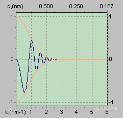
The presence of zeros in CTF means that we have gaps in the output signal. Obviously, the best CTF is the one with the fewest zeros and with the broadest band of good transmittance (where CTF is close to -1). 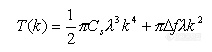
Back in 1949 Scherzer suggested an optimum defocus condition which occurs at: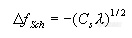
The presence of zeros in CTF means that we have gaps in the output signal. Obviously, the best CTF is the one with the fewest zeros and with the broadest band of good transmittance (where CTF is close to -1).
this value is now called "1 scherzer".
Note: sometimes the value of 1.2 scherzer is called "Scherzer defocus" (we are going to call the value of 1.2 scherzer as "extended scherzer" throughout this manual). "Extended scherzer" provides even broader band of transmittance with CTF still close enough to -1.
Figures below show CTF's for different defoci values for a 200 keV microscope.
(Blue curve: CTF, Orange curve: combined damping envelopes).
Defocus: 1 scherzer ("True" Scherzer defocus)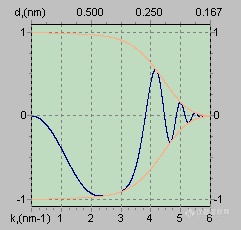
Defocus: 1.2 scherzer ("Extended" Scherzer defocus). In general, this is the best defocus to take HR-TEM images.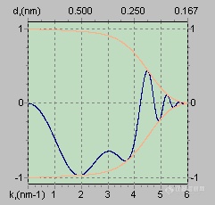
Defocus: 1.9 scherzer ("2nd Passband" defocus). Produces a nice and broad passband which starts NOT at zero. CTF is positive so that it produces a negative phase contrast ("white atoms")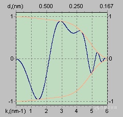
Defocus: 0.4 scherzer ("Minimum Contrast" defocus).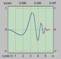
Defocus: 0 (low contrast, not good). Note: Zero-defocus images are NOT "Minimum Contrast" images. Minimum contrast occurs at about 0.4 scherzer (shown above).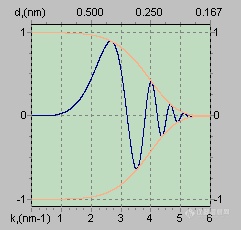
Defocus: 10 scherzer (large and generally not good for HR-TEM)